BETAQDAVE
-
Posts
5,386 -
Joined
-
Last visited
Content Type
Profiles
Forums
Gallery
Events
Everything posted by BETAQDAVE
-

Homemade Spray Booth
BETAQDAVE replied to BETAQDAVE's topic in Modeling tools and Workshop Equipment
Not much time today, but did manage to finish painting everything on the booth with the exception of the top panel which needs a lot of work yet. I managed to tip the booth onto its backside to paint the bottom side of the bottom panel and took this photo from the top. You can see the layout of the plenum from this view.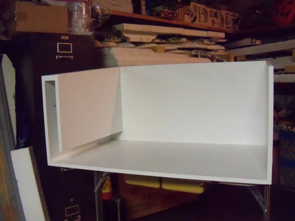
-
Homemade Spray Booth
BETAQDAVE replied to BETAQDAVE's topic in Modeling tools and Workshop Equipment
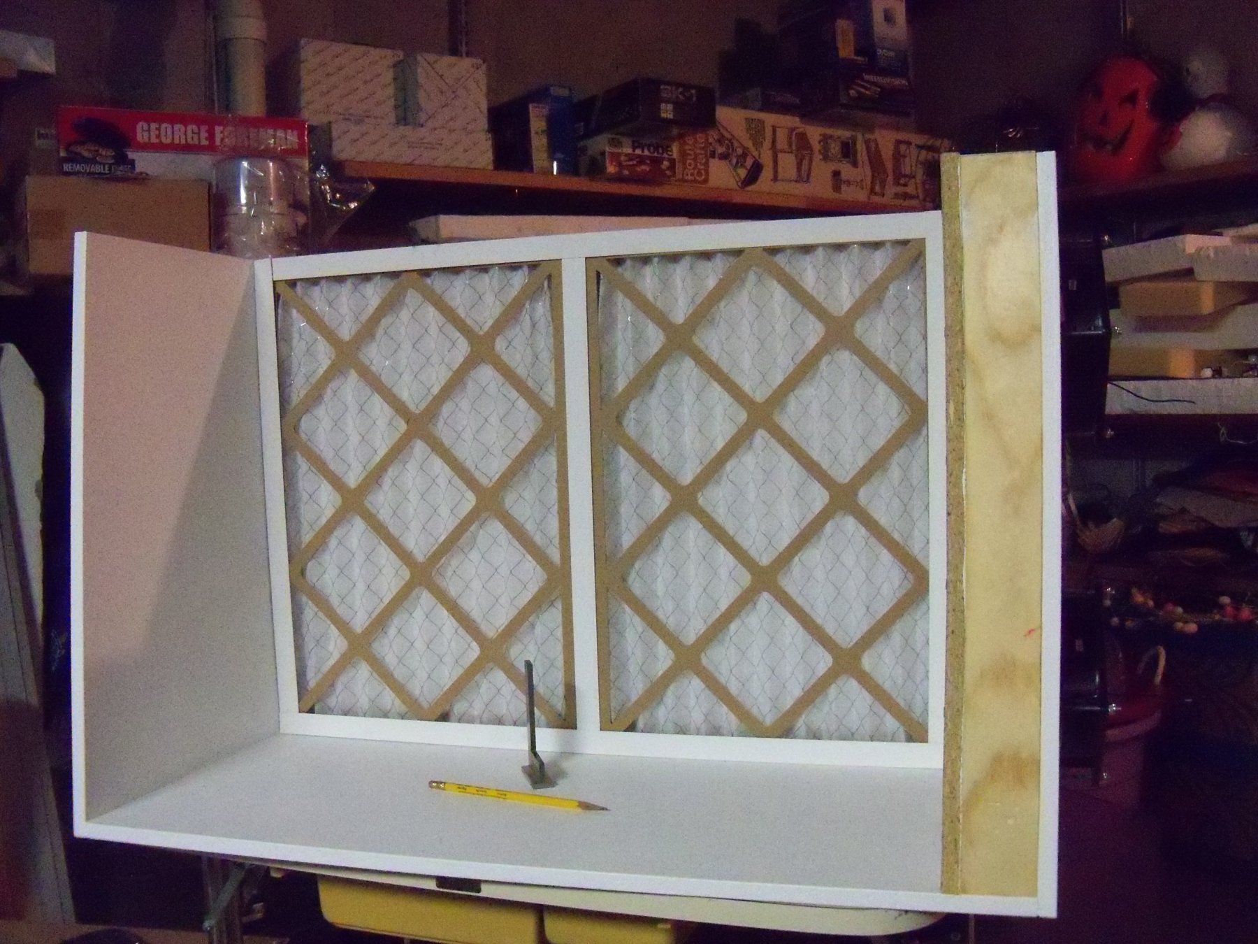
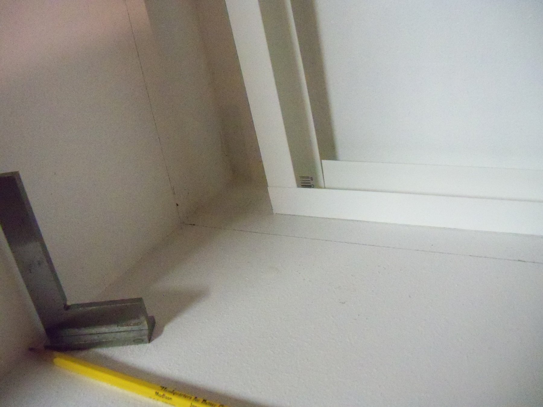
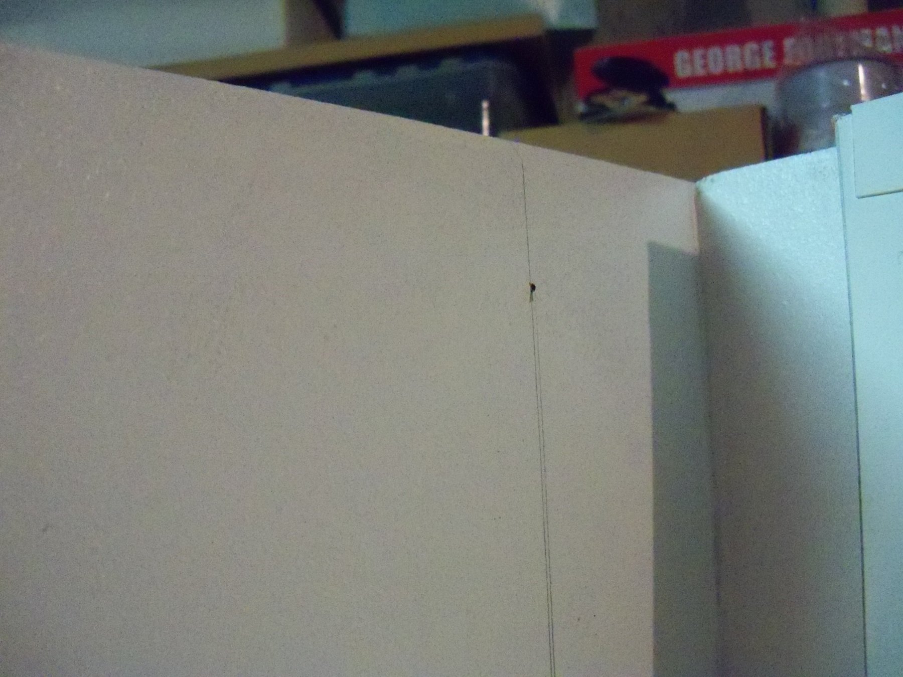
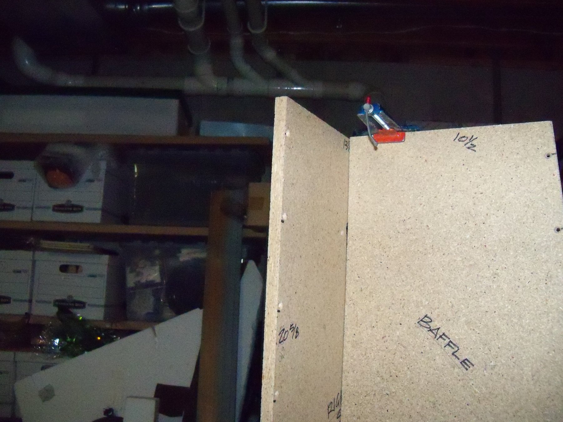
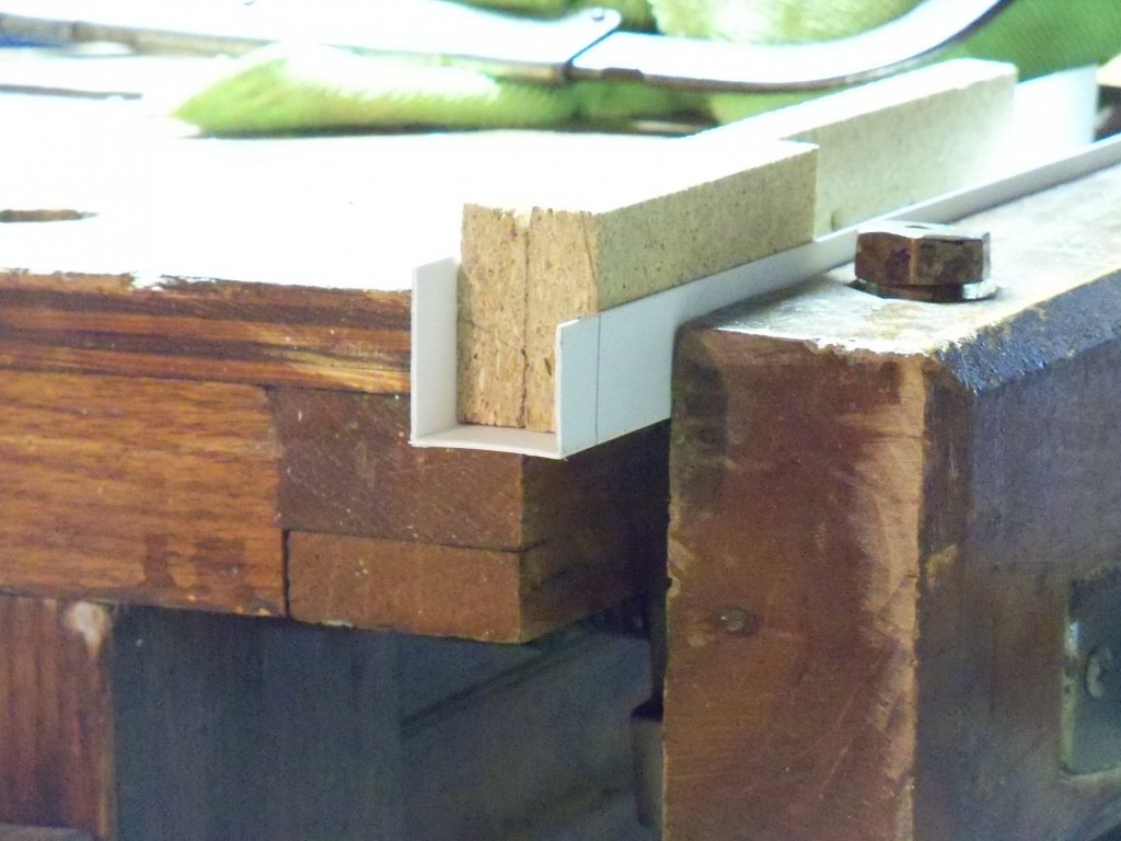
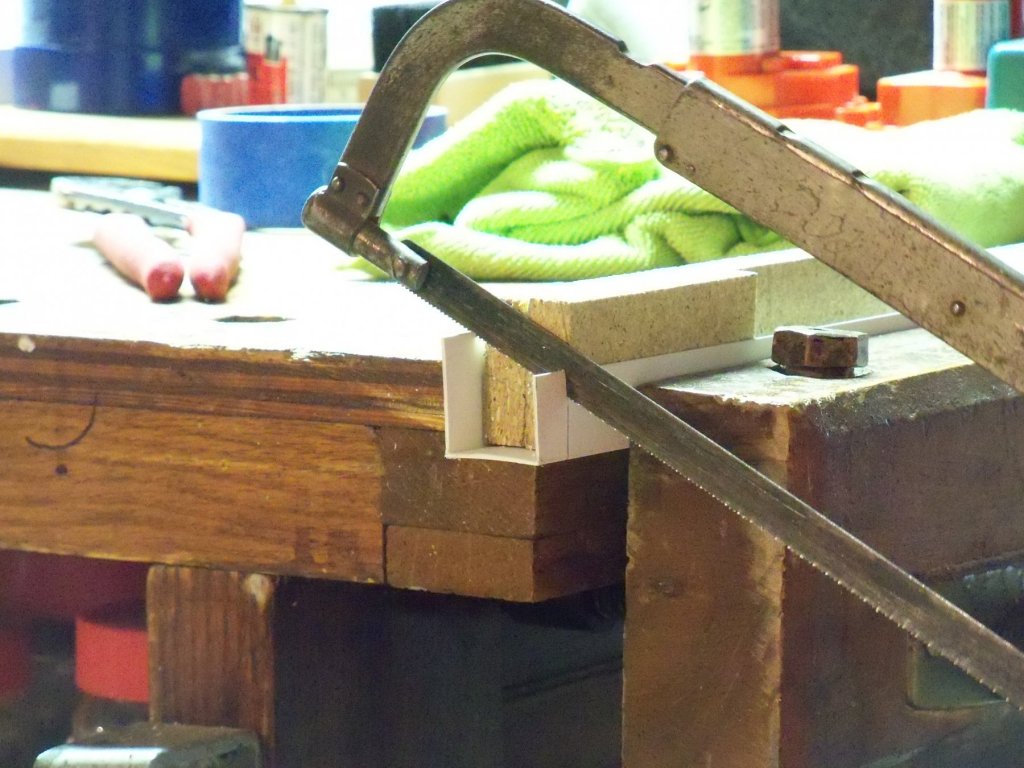
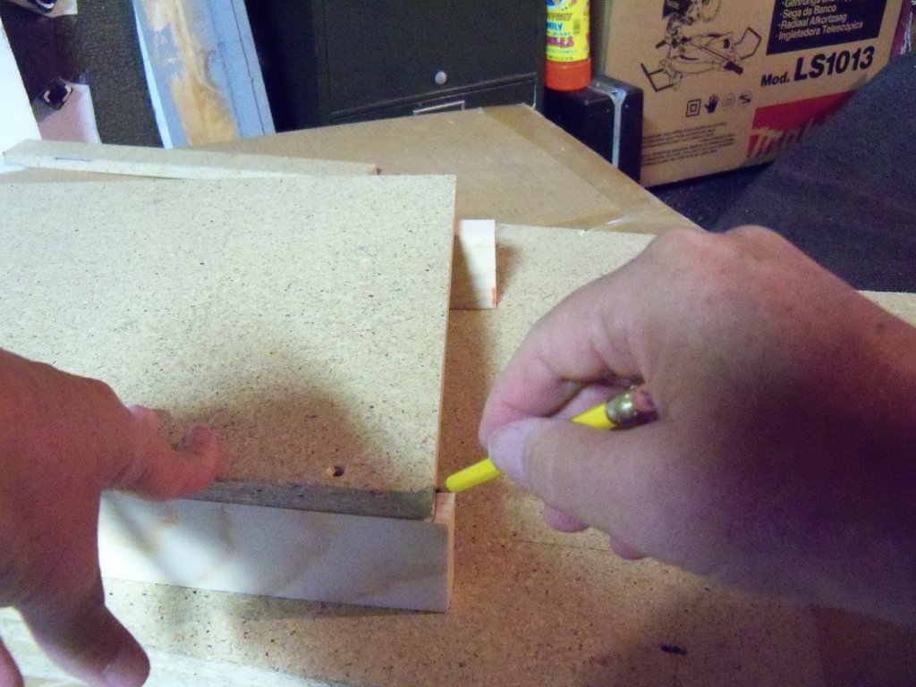
Now that the glue has had two days to set up it was time to put in the plenum cover. Once I got to this point, I realized that the cover should have been attached to the right side panel during the last step when I would only have needed to glue up the bottom and one side of the cover. Now I have to butter up both sides and the bottom at the same time! To keep from scraping the glue off while sliding the cover in place, I planed about 1/16” off one edge. I clamped the cover in place so that I could drill through the baffle and right end panel into the cover. Taking the cover out, those holes were countersunk as before to allow for a tighter fit. Going to the yellow carpenters glue bottle again, the edges and bottom end were buttered up with a heavy coat and the panel was slipped back into place. Two of the screws on each side were driven into place with a hand screwdriver to seat into the predrilled holes and get everything properly aligned. The remaining screws were then driven home. The excess glue that squeezed out was removed with a damp cloth to finish the installation. Here is a photo at this point below. Now I decided to test fit the filters and their plastic supports. I found that the filters were actually a tight enough fit that the 1/8” hardboard shims were not really necessary after all. All of the plastic U channels were then trimmed for a tight fit for later installation. Cutting the plastic U Channel was difficult at first until I realized that there was an easier way to do it without having the saw chatter its way through it. Marking the cut with a pencil and a small square, the piece to be trimmed was clamped in my vice with two scraps of ½ inch particle board in the gap. The scraps were lined up with the cut line even with the mark and the line was placed very close to the end of the vice jaws. Now with a hack saw, the blade just used the end of the scraps for a guide. The chatter was minimized and the cut was square. While still in the vice, a sanding block was used to smooth the cut. I also decided to fit a section of T channel to fit between the filters in the center. At this point everything was fitting properly as shown below. Taking the filter assembly out, I used more glue to make the fillet for the bottom of the baffle. Now using a pencil, I marked a line three inches in from the back panel on the bottom and both sides to locate the inside edges of the filter assembly. As the baffle still needed to be painted, a small drill was used to make an impression in the panels so that when the line was painted it could still be used as a guide to relocate the face of the filter frame. Hopefully, I can get back into the shop tomorrow to paint the booth assembly and begin making the top.


-
Homemade Spray Booth
BETAQDAVE replied to BETAQDAVE's topic in Modeling tools and Workshop Equipment
-
Who can say just how long any of us have on this earth? Our very existence is always subject to coming to an abrupt end when we least expect it! I feel that if we all lived our lives avoiding doing the things that we like to do just because we aren't sure if we can finish them, none of us would be able to enjoy what time we do have and would never be able to get anything done at all. I have listed many projects that I look forward to doing below, that realistically I probably wont be able to, but I fully intend to give it a good try anyway! Do your logs and enjoy another facet of modeling, you will find that we all try giving advice on how to get through the difficulties that more than likely many of us have already run into.
-
Homemade Spray Booth
BETAQDAVE replied to BETAQDAVE's topic in Modeling tools and Workshop Equipment
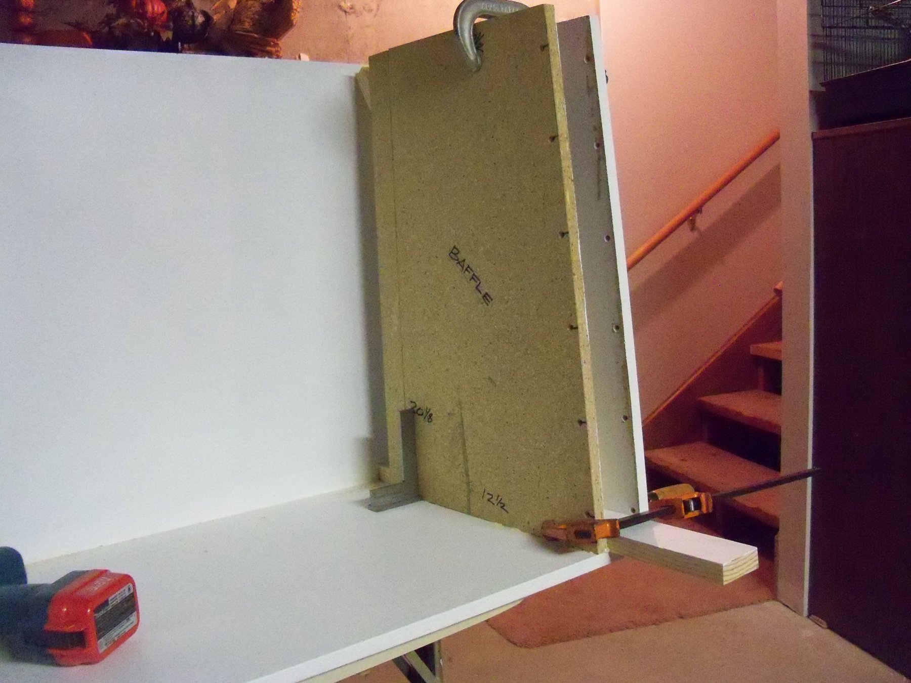
There have been many things keeping me away from this project lately including the elevator problems, the downed tree, a couple of funerals, and just life in general, but I did get a break yesterday to get at it again. The fans were bolted to the right end panel with a bit of caulk around the edges to maintain a good air seal. This had to be done before installing the baffle as the inside end of the stove bolts would be very tough to access in the 2 inch space once that was attached. The next step was to clamp the baffle panel in place to allow me to align the holes in the bottom panel with the bottom edge of the baffle and drill into the bottom of it. It was becoming too difficult to wrestle the heavy assembly around on the assembly table from the wheelchair to allow me to tilt it back on its backside, so I just clamped it in place as shown. It did however; make it a bit awkward keeping the drill perpendicular to the surface of the bottom panel while drilling straight up through the bottom so the bit would stay in the center of the baffle panel. The clamps were removed at this point to allow me to countersink the holes that I just drilled in the bottom edge of the baffle panel. Next, I buttered up the bottom edge of the baffle with a heavy coat of yellow wood glue. The assembly was clamped together again and the screws were driven home. The Plenum cover was slid into place and that was clamped as shown here to sit overnight for the glue to set up.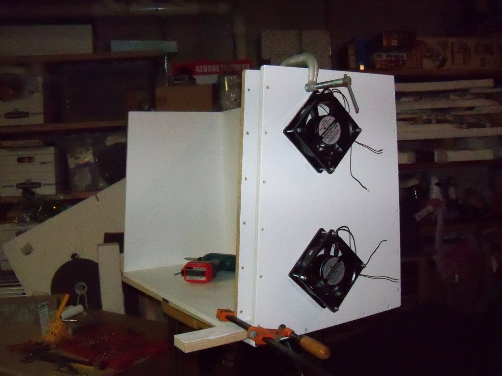

-
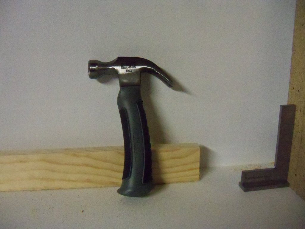
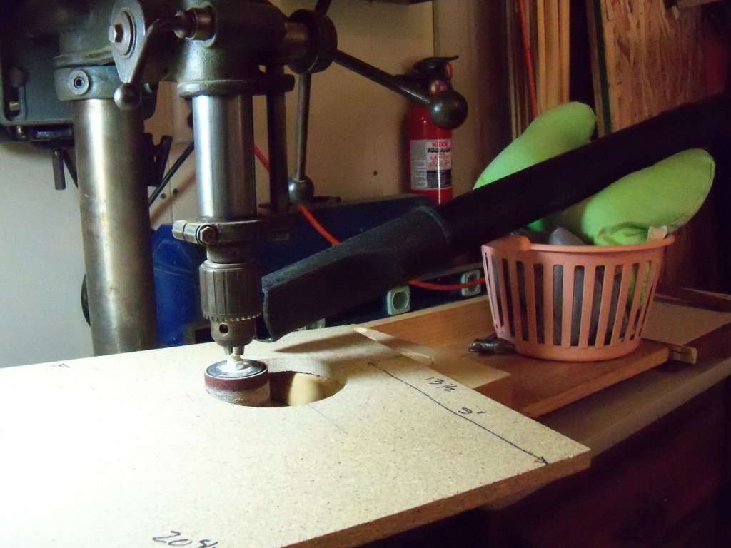
While in the hardware store the other day I came across this very handy tool. Try to imagine if you will, an 8 oz. carpenters hammer with a shortened contoured grip handle. Well, that is just what we have here. That is a 4" magnetic mechanics square beside it to give you an idea of its size. With my limited strength due to my MD, a standard hammer has become an unwieldy tool. However, this baby gives me a tool that is easily griped and still provides enough heft to drive standard nails or pound things into place. This model is made by Master Mechanic, and for people with normal strength, it's perfect for swinging in tight spots. I have a one handed sledge, a 20 oz. framing hammer, and several 16 and 8 oz. standard hammers, but they are of little use to me now. Of course I also have numerous small specialty modeling hammers, but they are likewise of little use when doing regular carpentry projects. For me, this fills a need that I never even realized that I had!
-
My recommendation of the book Rigging Period Fore-And-Aft Craft by Lennarth Petersson seems to have stirred up a bit of controversy over its net worth as a reference. From some of the reactions, I feel that I need to offer some defense of my recommendation. Some of us, me included, find it and its companion book, Rigging Period Ship Models, to be useful additions to our maritime libraries. Others seem to think that the books are just rip-offs of some sort. I’d like to let everyone else here decide the merits of the books for themselves. Here is some food for thought. If one would just read the introductions of these books by the author you would find that he is not saying that his book should be taken as some kind of gospel on rigging, but rather a review of the rigging on some actual models that were built in the same time period that the ships being modeled existed. Some restorations may have been done incorrectly or the original model may even have been done in error to start with, but then again, correcting errors was not the stated purpose of his books. In any case, right or wrong, the illustrations he made were done to show the way the rigging was done on the MODEL, not necessarily the actual SHIP. After all, if you were like the author, who admittedly was just an amateur modeler himself, would you have the presumption to second guess the modelers details found in a respected museum made by knowledgeable people with first hand information that you could never have? I would think that the very fact that they were in a museum would lead me to believe that they must have had some measure of accuracy and quality to be there in the first place. And one more thought here, as far as historical accuracy goes, who would know beter how it actually was on that particular ship anyway,……a model builder from the same era of the ship, or someone else critiquing that model centuries removed? Here are some actual excerpts I have taken from the introduction on page 1 of Rigging Period Ship Models by Lennarth Petersson: …..”I felt it important, both for the sake of accuracy and for the benefit of modelers, to draw from a contemporary model, and I decided on an English frigate which should have retained most of its original rigging. By going to a three dimensional source I hoped to be able to depict the intricate details in the clearest possible manner, and by choosing a contemporary model create a scheme which was authentic. With the help of my publisher I found a suitable model, with much of its original rigging intact, in the Bristol Industrial Museum. It is a beautiful model of the Melampus, a 36-gun, 18-pounder frigate. It was donated to the museum in 1844 and while it has received the attention of restorers over the years its rigging is considered a reliable representation. I photographed and sketched the model from every angle and the results of the exercise were the source for the drawings in this book”. “She is one of four models of ships which were built by the Bristol yard of James Martin Millhouse and is assumed to have been commissioned by the builders.” “I hope this book will make the task of rigging easier for modelmakers at all levels. Certainly, researching and drawing out the illustrations answered a lot of questions for me. There are other works which any modelmaker needs to refer to and which have been stalwart guides for me. Foremost are James Lee’s The Masting and Rigging of English Ships of War 1625-1860, and C N Longridge’s The Anatomy of Nelson’s Ships. Any modeler's book shelf also requires The Ashley Book of Knots. Finally, the journal Seaways and The Nautical Research Journal, from Nautical Research Guild in the US, have been useful guides for me.” As you can see above, he has even suggested some sources to refer to for more clarification on the details. (Notice that he has even listed The Nautical Research Journal there.) And here are a couple more excerpts I have taken from the introduction on pages 7 and 8 of Rigging Fore-And-Aft Craft by Lennarth Petersson: …”the more I became familiar with the ships, the more I have realized the limits of my own knowledge. I have, as in the previous book, attempted to describe and illustrate no more than the rigs of these vessels. Readers wanting more information on the design, construction and careers of these sorts of craft will need to look elsewhere.” “The book is not intended to be an academic contribution to the field of maritime historical research; as a visual study based solely on three models it is rather intended as an accessible guide for the enthusiast and model shipwright. These contemporary models were all made by people well acquainted with the vessels of the period, and so they can be seen as representing some of the best evidence of the way these craft were rigged.” I think that in the first line of the last excerpt he has stated his purpose of writing these books quite clearly. Some of us may still feel that he did not, but that is an opinion which is something that we are all entitled to have. As I said, we each have our own opinions on the mater, but mine is that one should not really expect this book (that is freely admitted by the author in the introductions to be merely illustrating a specific models’ details) to be some kind of technical manual of proper rigging methods. The author has again provided his readers with other sources to do just that with. I hate to say this, but isn’t that what you are doing concerning the efforts of the model builders work that is described by the author, not to mention the authors efforts to illustrate them? I personally feel that there is too much destructive criticism here (and apparently previously back in 2017) about the models and the books illustrating them. While you have shown that there were certainly errors shown in the book, (what book doesn't have them?) there must be be some redeeming qualities in it since you seem to have a copy yourself that you continue referring to. Might I suggest that rather than just pointing out what you feel to be incorrect details in the book, could you show us the correct method to clarify the way you think it should have been shown? I think constructive criticism on the subject would be of much more use to the rest of us. I apologize if I have stepped on some toes here, but as I think I have shown in this post here, my opinion (for what it's worth) is that as the books in question here were never intended to be technical manuals don't try using them as such.
-
Nice video Ron. I have made a version of most of them myself, both for my full size saw and my MicroLux hobby saw. One thing that I noticed on the video that is of some concern however is that on almost all of the cuts that he makes, his body acts as a stop for his cutoffs. One thing that was always stressed to me in all my shop training is to NEVER stand directly in the path of your cutoffs. That powerful motor can propel that cutoff with sufficient force to cause great bodily harm to you. (or anyone standing behind you in its path) One student in one of my classes was not paying heed to this rule and was skewered by a long thin cutoff of Ebony that went right thru his shirt and shop apron into his abdomen where it remained lodged until it was removed in the ER! While that was bad enough, they were unable to remove some undetected slivers of Ebony and cloth fibers that caused an infection to set in that led to his death! While this accident was an extreme case, I am sure that similar incidents have happened before and since. After all, I have seen a piece of straw driven thru a 2 X 4 from a tornado once, so with sufficient force even straw can become lethal. He says several times in the video "safety first", but I guess he is unaware of the danger he puts himself in.
-
There is no accounting for the dishonesty or lack of integrity of some people when they do something that they think no one has witnessed. Working at a lumber yard where I had worked for 20 some years and was (I thought) friendly with my fellow employees, there was an accident in the parking lot where our trucks are often loaded or semis unloaded. My new car (purchased just two days prior to the mishap) had some long and deep scratches on the rear bumper that I was unaware of until leaving work for the day. It was obviously done by one of the yard workers running a forklift of lumber across the yard way too close to my car, but asking if anyone knew what happened, no one would fess up to doing it or even witnessing the accident and of course you know who had to pay for it! I have suffered several other incidents very similar in nature, so I personally tend to believe that things like that happen all the time.
-
I looked for other magazine articles on whaling ships after mentioning the ones above and came up with a few more. -Model Ship Builder magazine Jan/Feb 1981 issue has an extensive article by Jim Roberts titled Masting And Rigging The Whaling Brig Kate Cory. -Model Ship Builder Mar/Apr 1981 also by Jim Roberts covering hull and deck details for the Kate Cory. -Ships-In-Scale Jan/Feb 1986 by Robert Evans on modeling try works. -S-I-S also Jan/Feb 1886 by Jim Roberts on misc. features of whalers. -S-I-S Mar/Apr 1986 - May/Jun 1989 by Robert Evans on modeling the whaler Charles W, Morgan. - S-I-S May/Jun - Sep/Oct 1985 by James Adair also on modeling the C.W.M. And don't forget all the build logs on various whalers in MSWs forums.
-
I have heard mentioned on this forum that a mixture of salt and vinegar can be applied and once aged should be sealed with varnish. (I think it was mentioned in the Syren build log by Dubz.) Another one that comes to mind is the application of sun tan oil and being placed in direct sunlight. This one was also sealed with varnish once you get the effect you want. I think both methods are done once the plates are applied.
-
According to the manufacturers, they are left thick to protect them from being broken when packaged or shipped. The stern is also done that way for the same reason.
-
I have tried both methods and as I am currently building the Phantom, I am of the opinion that they should be taken off. I took it one step farther, by carving the additional thickness of the planking off of that portion of the hull above the coppered bottom. (There was no reason to carve and re-plank below the coppered area as it will be covered anyway.) Then I notched the hull for the stanchions to give me something to apply the planked bulwarks to. (This also makes it easier to put the scuppers in.) The only thing that I would do different would be to put a very slight bevel to edge of the planks, as once the hull is painted it is very hard to discern the individual planks. If you have access to old issues of Seaways Ships-In-Scale magazine in the May/June 1992 issue, there is a description of a process similar to my method used by Robert Evans on building your MS Kate Cory kit. There is also an article on building the Mary Taylor by Clare Hess in the same magazine from the March/April through July/August 2013 issues using a similar method.
-
Homemade Spray Booth
BETAQDAVE replied to BETAQDAVE's topic in Modeling tools and Workshop Equipment
Once again, I was short on time for the booth today. Given the fact that particle board is notorious for reacting to changes in humidity, I really don’t want it to warp out of shape. The fact that this is a portable booth and will probably see a lot of humidity changes it will be given a few coats of paint to seal it. Since all of the joints to be glued are done, I thought today would be a good time to get at least one coat applied. I had some left over white satin enamel paint, so I thought this would be a good way to use up some of it. Only had time for one coat today so this is its’ current status.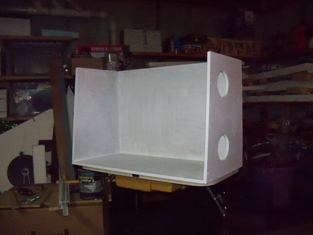
-
variable height desks
BETAQDAVE replied to bigcreekdad's topic in Modeling tools and Workshop Equipment
I used to do a lot of architectural designs at home as a side job for some 30 years on this table purchased from a drafting supply company. It has a power lift and it manually adjusts the tilt from flat to vertical. Some of the designs I drew up were on 36" x 48" sheets, so standing at the table with it in the full vertical position was the only way to reach the top of the sheets. I never used it for modeling as I never had any spare time back then, and since I became wheelchair bound the extra height isn't a useful feature anymore. As you can see now, it's only use is as a regular desk/bird playground.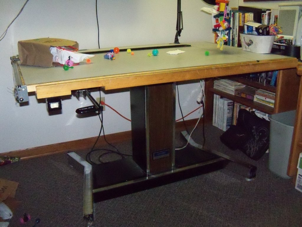
-
Homemade Spray Booth
BETAQDAVE replied to BETAQDAVE's topic in Modeling tools and Workshop Equipment
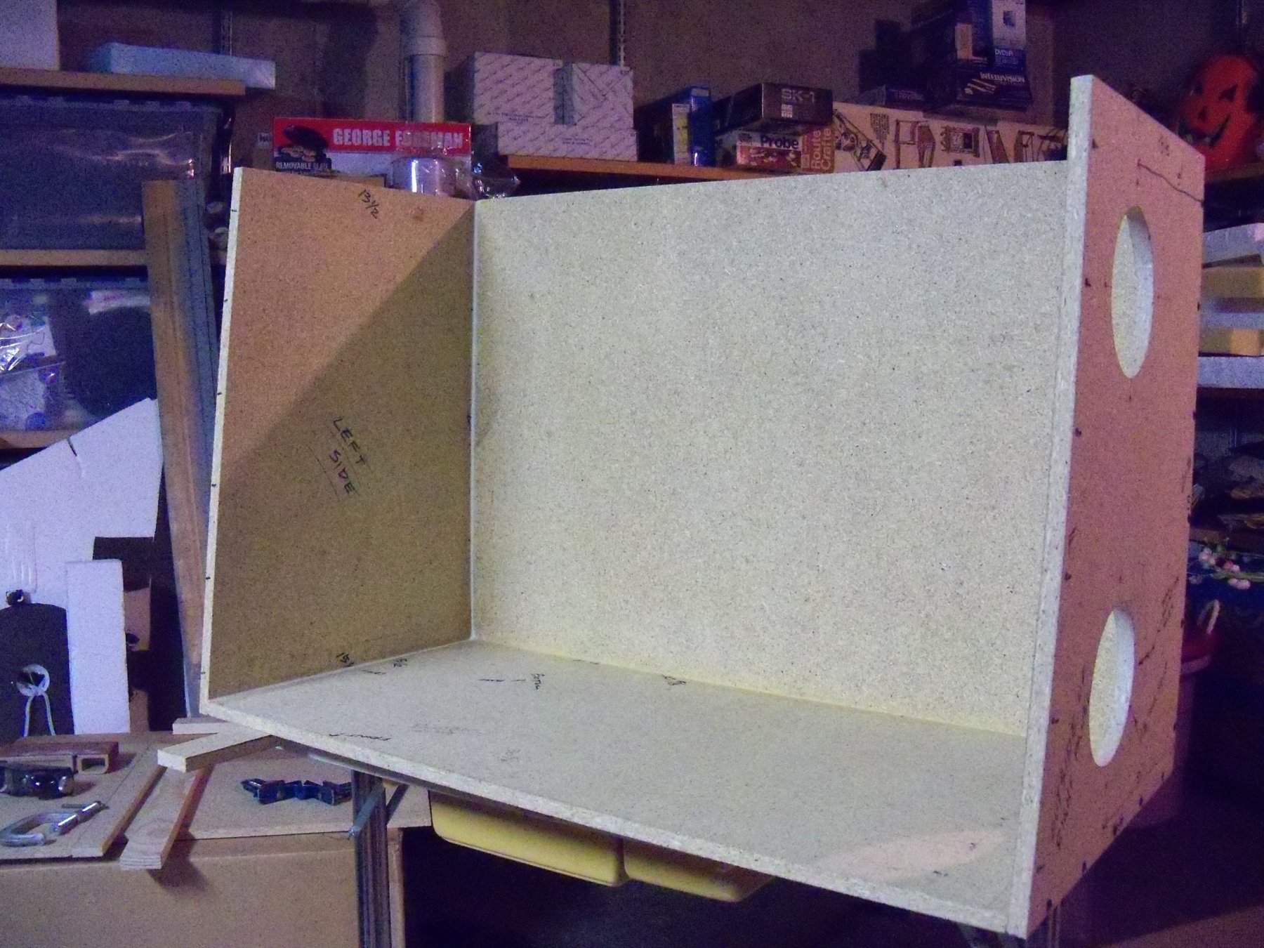
The previous step in the assembly has had a couple of days for the glue to set up, so it’s time to add the left side panel to the booth. I don't have much time today, but here is a short update. The procedure was similar to the previous steps: temporarily clamp it together, drill the holes through the predrilled holes into the edges of the bottom and back panels, disassemble it to slather on the glue, reassemble and clamp it back together, and then install and drive in the screws. Once the glue was given the fillet on the inside and the outside was cleaned up, it gets to sit for a day or two again. Here is a current status photo below.
-
Homemade Spray Booth
BETAQDAVE replied to BETAQDAVE's topic in Modeling tools and Workshop Equipment
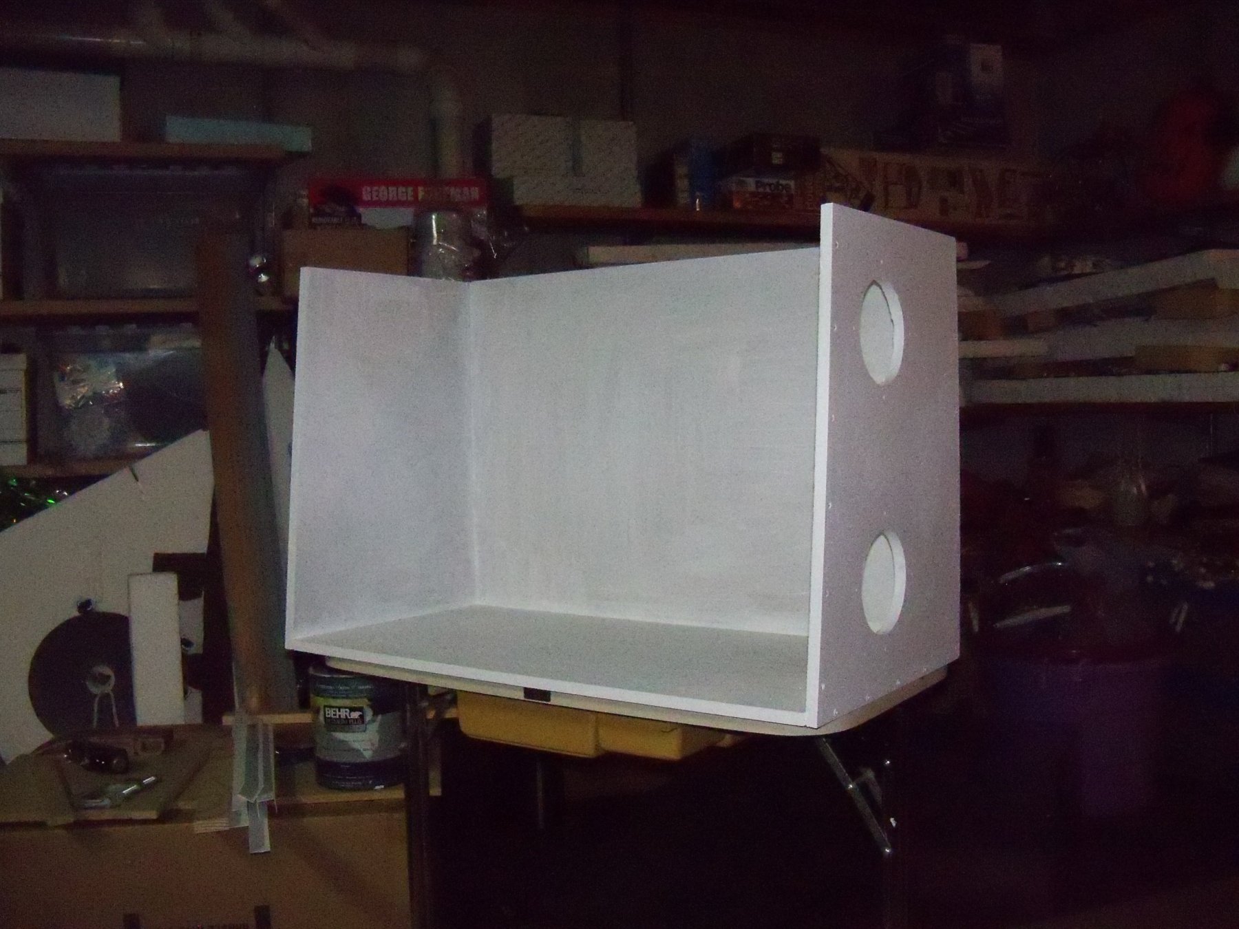
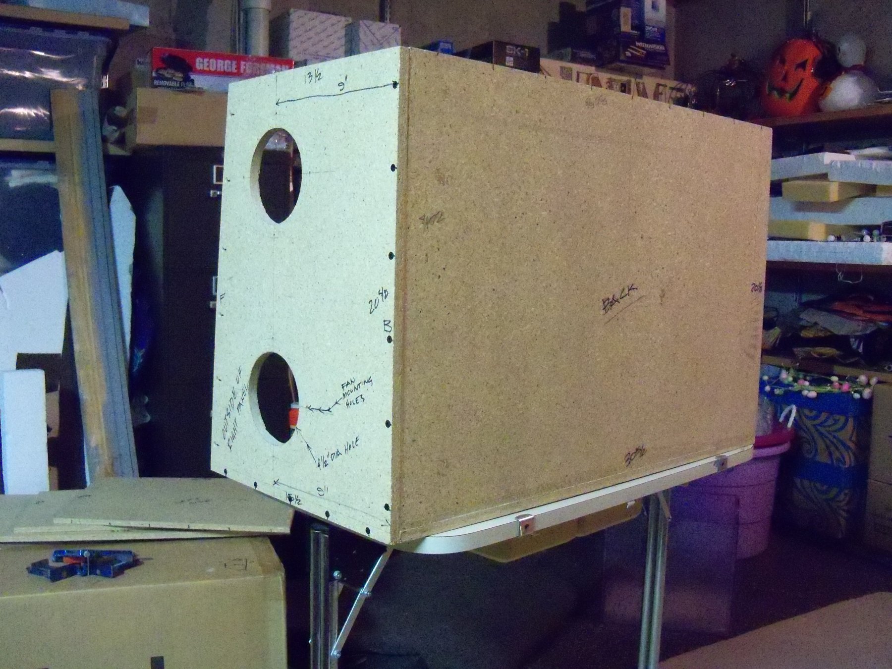
Now that I’m back from vacation, it’s time to get back to work on the booth. The back panel was the next part to attach and it’s the largest part to work with. I could have used more hands here, but I made do by balancing things on the roll around cart and some various clamps as shown below. Once everything was secured with clamps, I proceeded to drill through two of the predrilled holes in the right end panel into the edge of the back panel and drove in two screws to help hold it together while drilling the remaining holes. Then the assembly was flipped over to expose the bottom panel with its edge resting on the cart. Once again a couple of holes were drilled through the predrilled holes in the back panel into the edge of the bottom panel to help hold things in place to align and drill the remaining holes as shown below. Now the fun really began by unscrewing the back panel in order to apply the glue. Luckily the yellow wood glue I used has an extended set up time to allow me extra time to wrestle the parts into place and drive in the 15 screws required. The gluing was done similarly to the previous parts, but of course there was a much longer joint to glue up along the surface of both the bottom and right end panels. Once the glue was spread properly, the back panel needed to be placed in the glue on the face of the bottom panel and slid into the glue that was on the face of the right end panel. With the part precariously balanced on the cart with one hand, I took one screw in the other hand and screwed it partially by hand through the top of the right end panel to help steady the parts. Then while still holding the back panel in place with one hand, I put a miter clamp on the other end of the back and bottom panels with the other. Now that things were loosely held in place with the one partially driven screw and the clamp, I turned the cart around so I was facing the right end panel and placed the remaining five screws in place and drove them all with my impact driver to pull the joint up tight. The whole assembly was then flipped to place the face of the back panel onto the cart, being very careful not to dislodge the miter clamp that was the only thing holding the other end together. Finally, I was able to place and drive home the nine remaining screws. The glue squeeze out on the inside of the booth was a bit thin, so a little more glue was spread on the joint to allow me to make the fillet on the joint as shown below. All that remained to do now was clean up the glue that squeezed out on the backside. Here is the backside of the booth as it stands now. Once again everything will sit awhile as the glue cures. The fact that the glue was spread so thickly, I thought giving it a little more time to set up would be a good idea.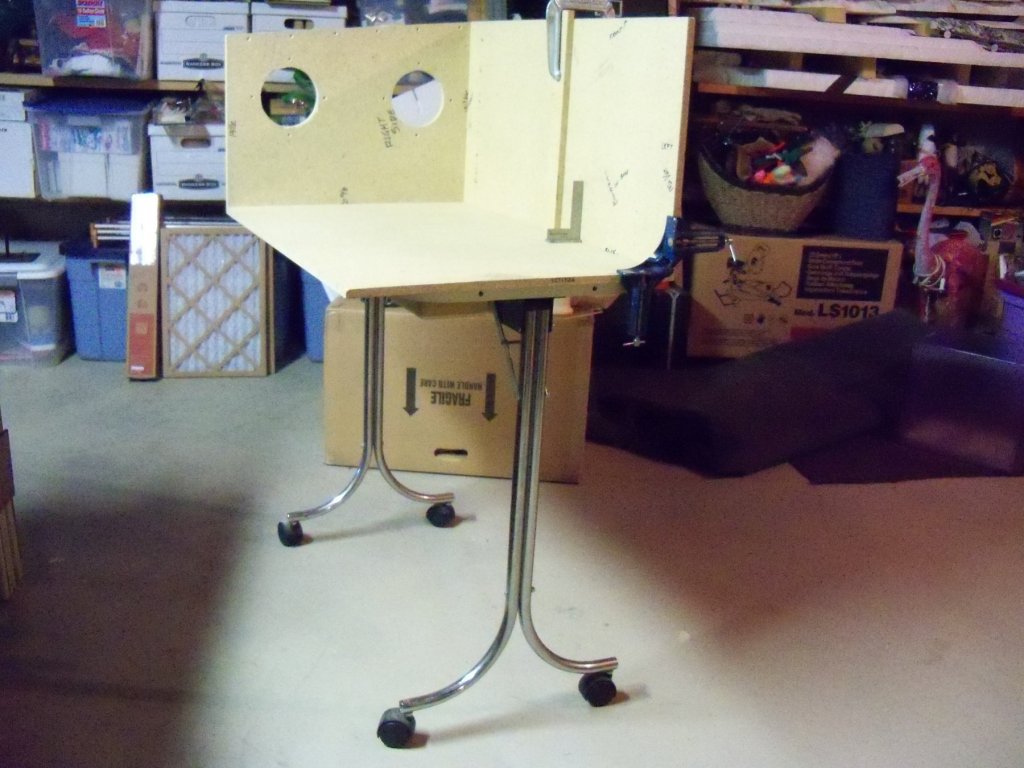

-
As was shown by your ingenuity at making an ordinary clothes pin into a custom clamp to hold your blocks! Reminds me of my grandfather who, due to necessity during the depression, had to make many of his own tools for his woodworking projects.
- 306 replies
-
- 4
-

-
- schooner
- la jacinthe
- (and 1 more)
-
This chopper was also featured in several movies including one of the Rambo films. (Rambo III I think). Have a look at the film for a good look at it in action.
-
Homemade Spray Booth
BETAQDAVE replied to BETAQDAVE's topic in Modeling tools and Workshop Equipment
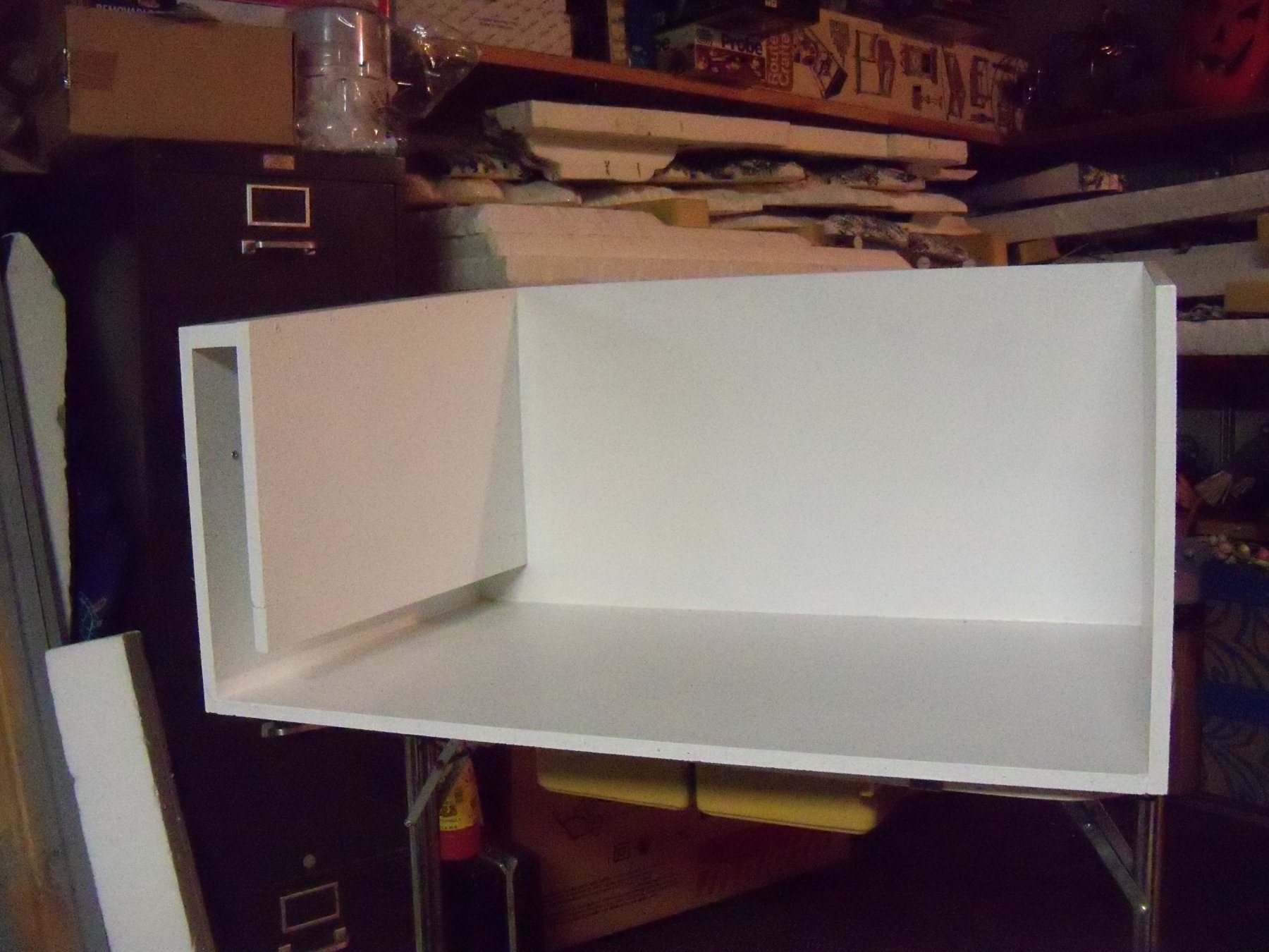
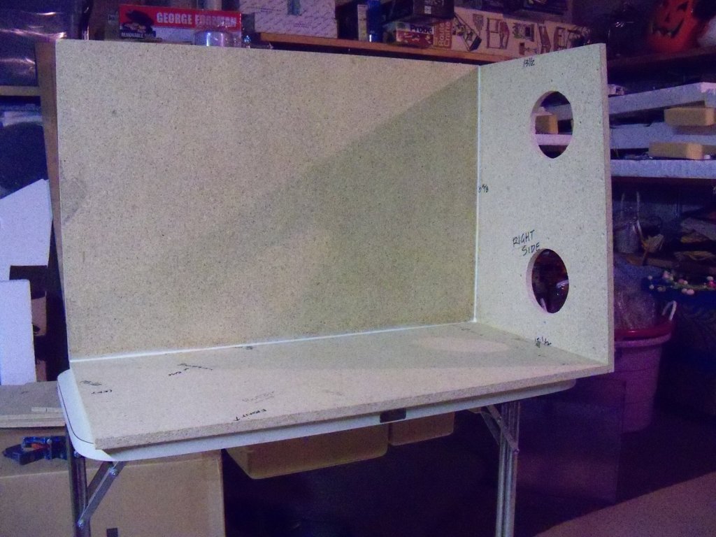
The assembly of the booth started out with the right side panel being attached to the right end of the bottom panel. The two pieces were propped in place temporarily to use the predrilled holes in the right side panel to locate and guide an 1/8” brad pointed wood drill bit into the edge of the bottom panel for pilot holes for the 1 5/8” square drive drywall screws. Once the holes were drilled, the parts were laid out on a movable assembly table for application of the wood glue. I drew a line ½” in from the edge of the right side panel and laid painters masking tape along that line to keep most of the heavy layer of glue confined to the area of the actual joint. The glue was spread in a continuous thick layer with a stick to ensure that the joint would be sealed from air leakage. When I finished applying the glue, the tape was removed. Once again the panels were set into place and two of the screws were partially driven in by hand to locate the pilot holes. I used the baffle panel with a clamp on the top to help hold the panels in place and to make sure the joint would form a good right angle joint. The other three screws were partially driven in place to check the alignment. When satisfied that everything was properly aligned, all five screws were driven home with my impact driver to get a good squeeze out of glue. Now that it was held together by the screws, the baffle was removed just long enough to take a damp rag to the joint to both remove the majority of the glue squeeze out and to form somewhat of a fillet of glue to make sure the joint was well sealed. The photo below shows this glue fillet. Now the baffle was re-clamped in place to maintain the right angle joint while the assembly was set aside to let the glue set up properly. I felt that this joint was the key to my assembly to allow the other components to be braced to them and not flex enough to break the seal of the glue fillet joint. Once this assembly sets properly I will use a similar procedure to attach the back panel. The following photos will show some of the details and how things stand at this time. We are leaving for a short vacation to Door County now, which should leave plenty of time for this key joint to set up properly. At this point I can readily see that this booth will be quite heavy and with my limited strength I may need some help to wrestle the rest of this thing together. It's a good thing that I planned on having a roll around stand to mount it to!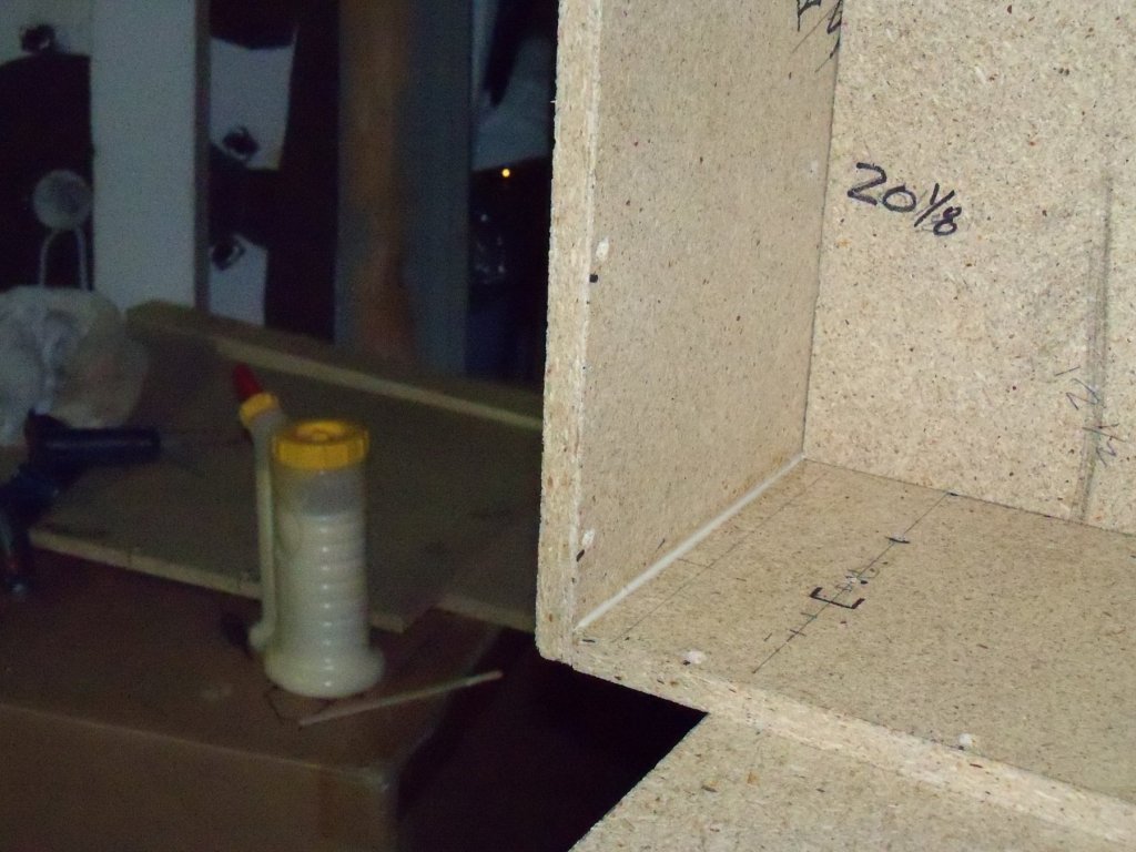

-
Homemade Spray Booth
BETAQDAVE replied to BETAQDAVE's topic in Modeling tools and Workshop Equipment
The fans are brush-less and supposed to be good for this application. -
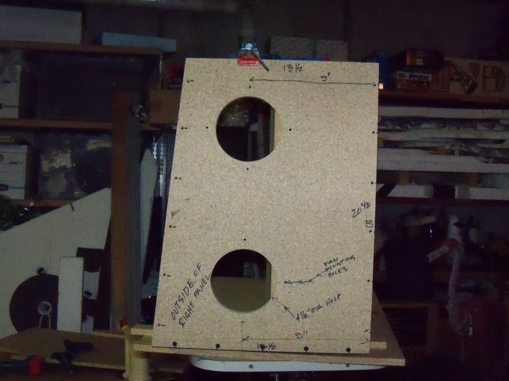
Homemade Spray Booth
BETAQDAVE replied to BETAQDAVE's topic in Modeling tools and Workshop Equipment
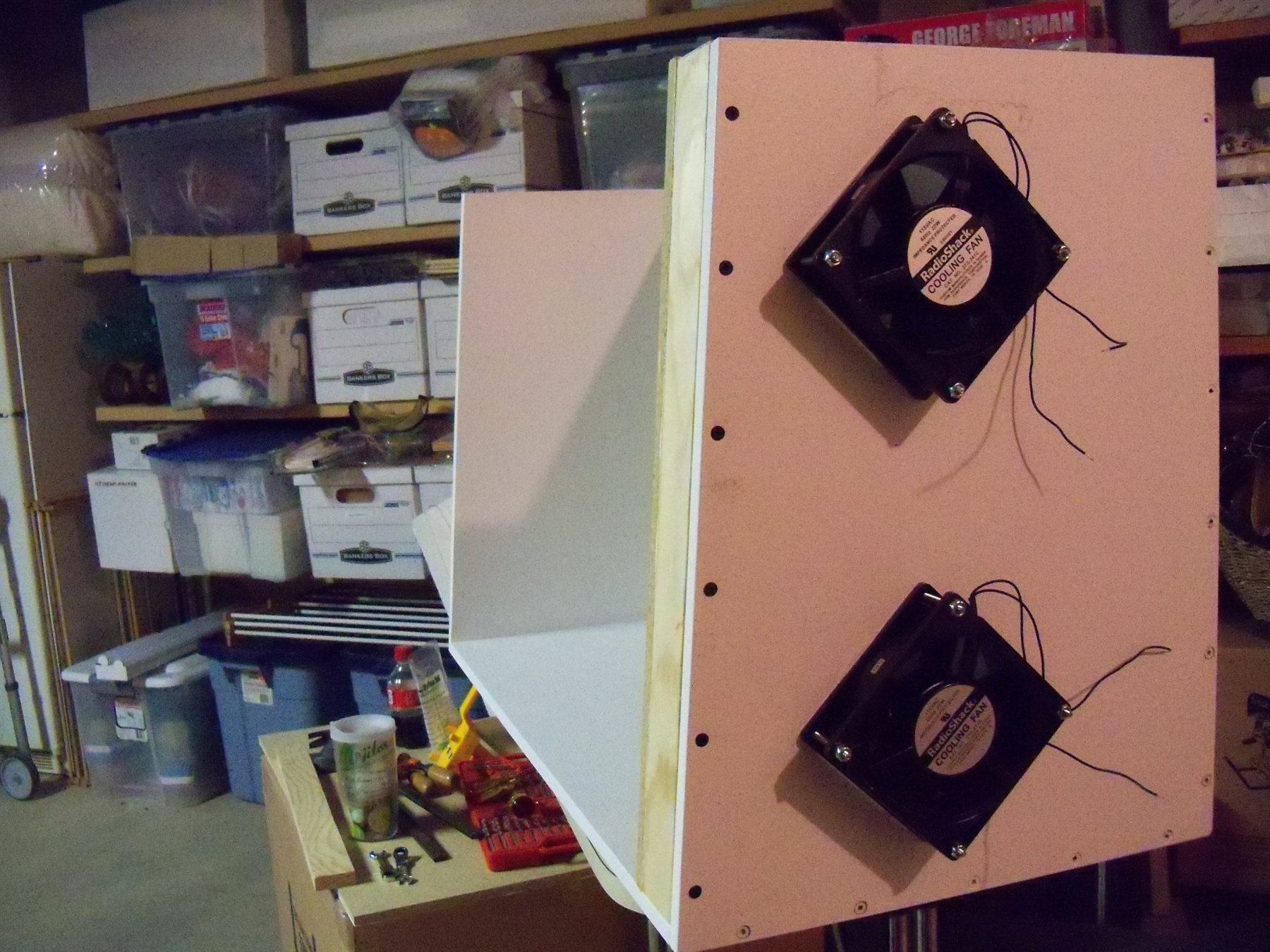
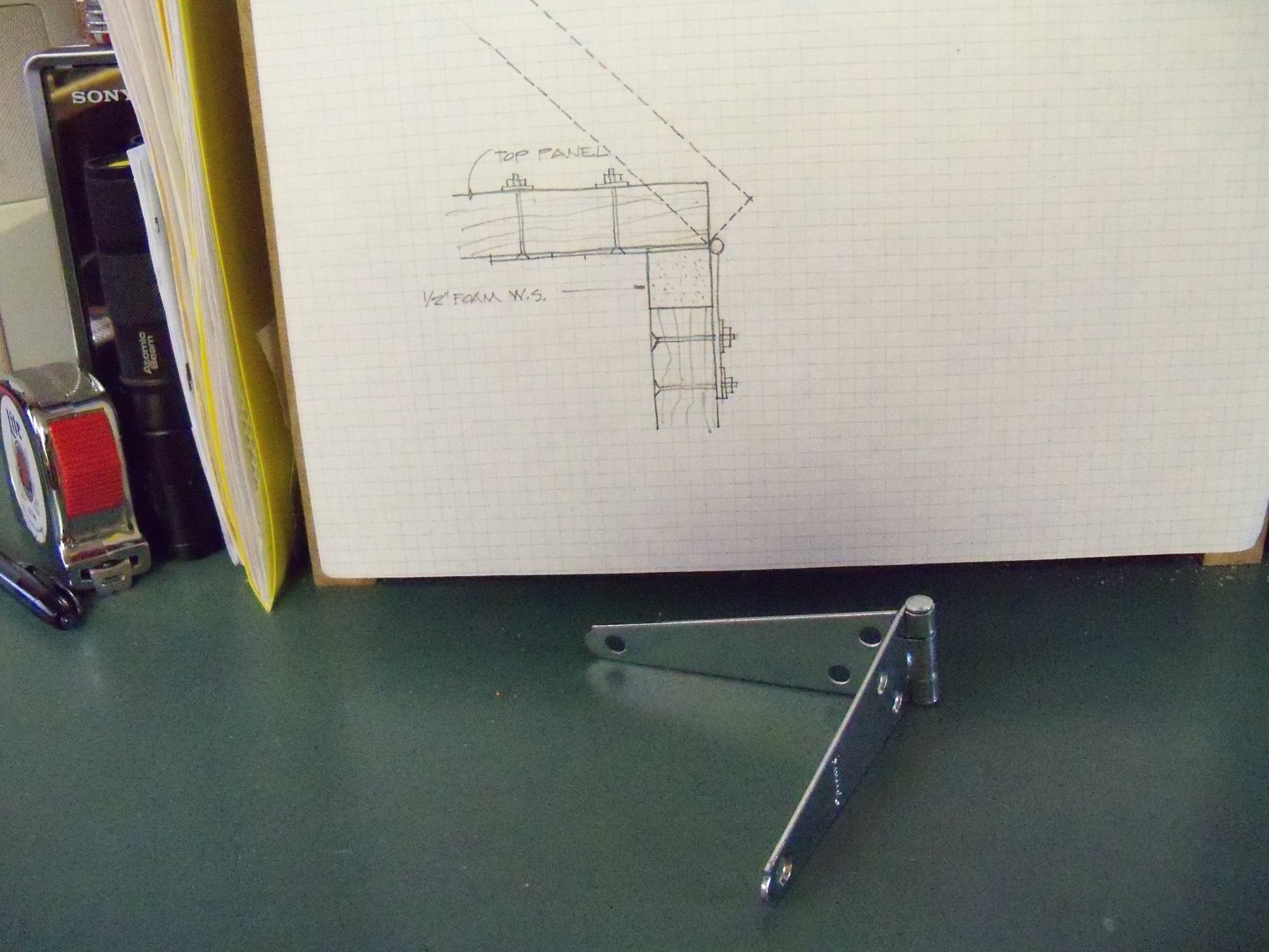
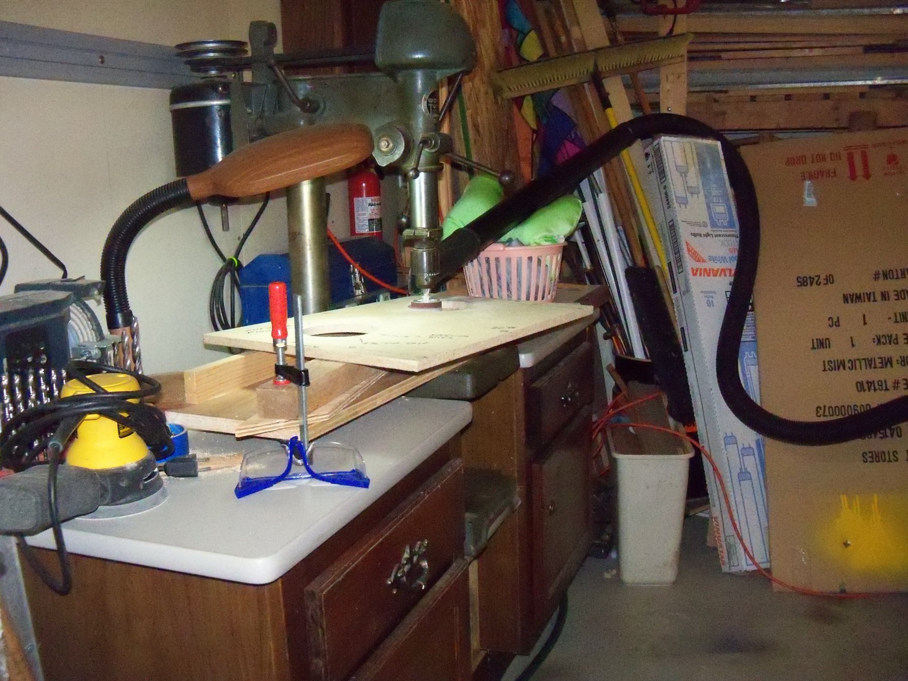
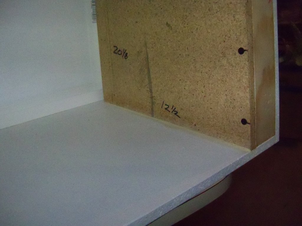
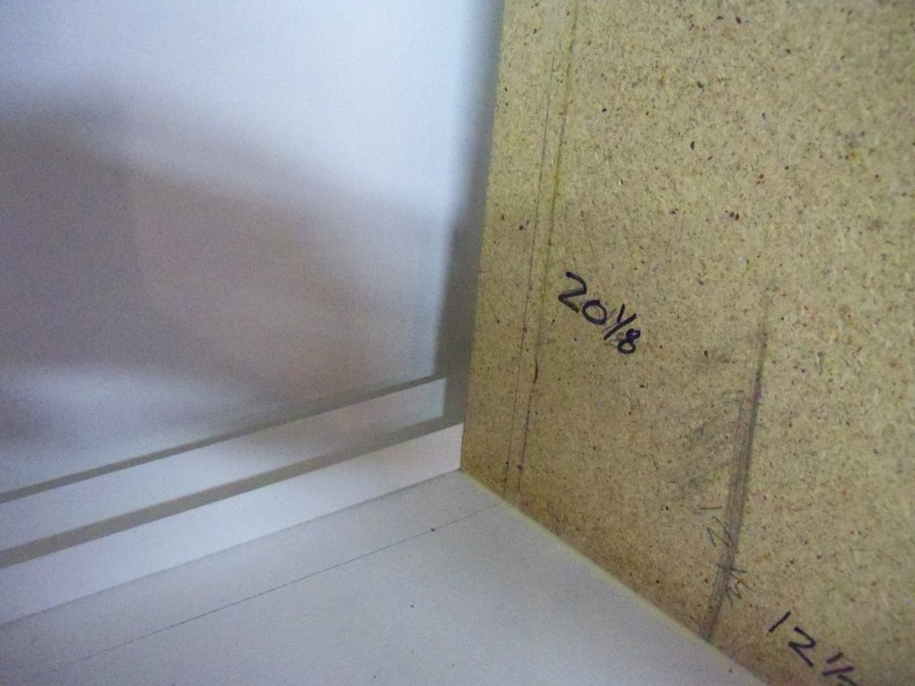
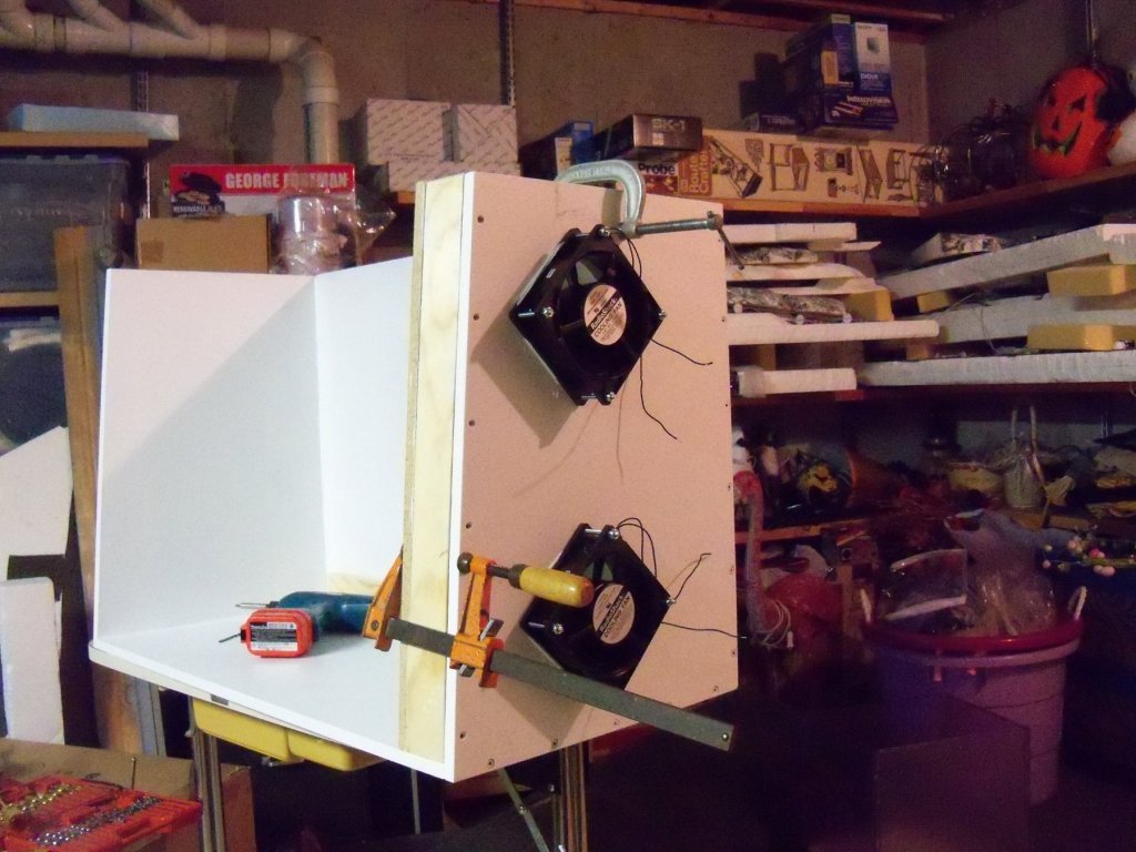
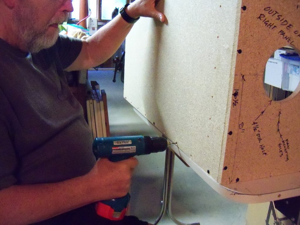
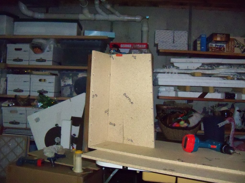
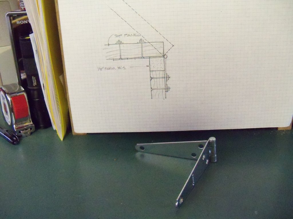
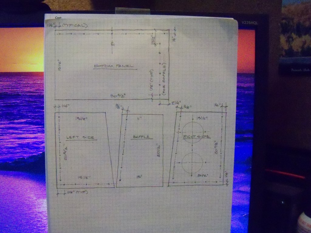
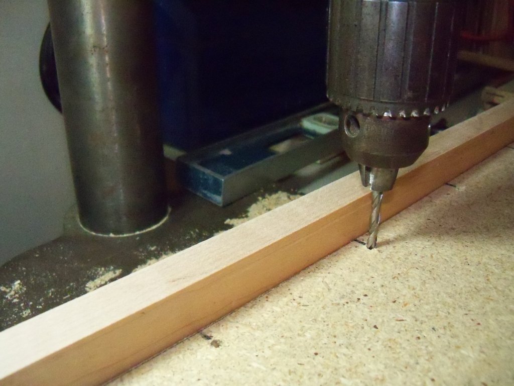
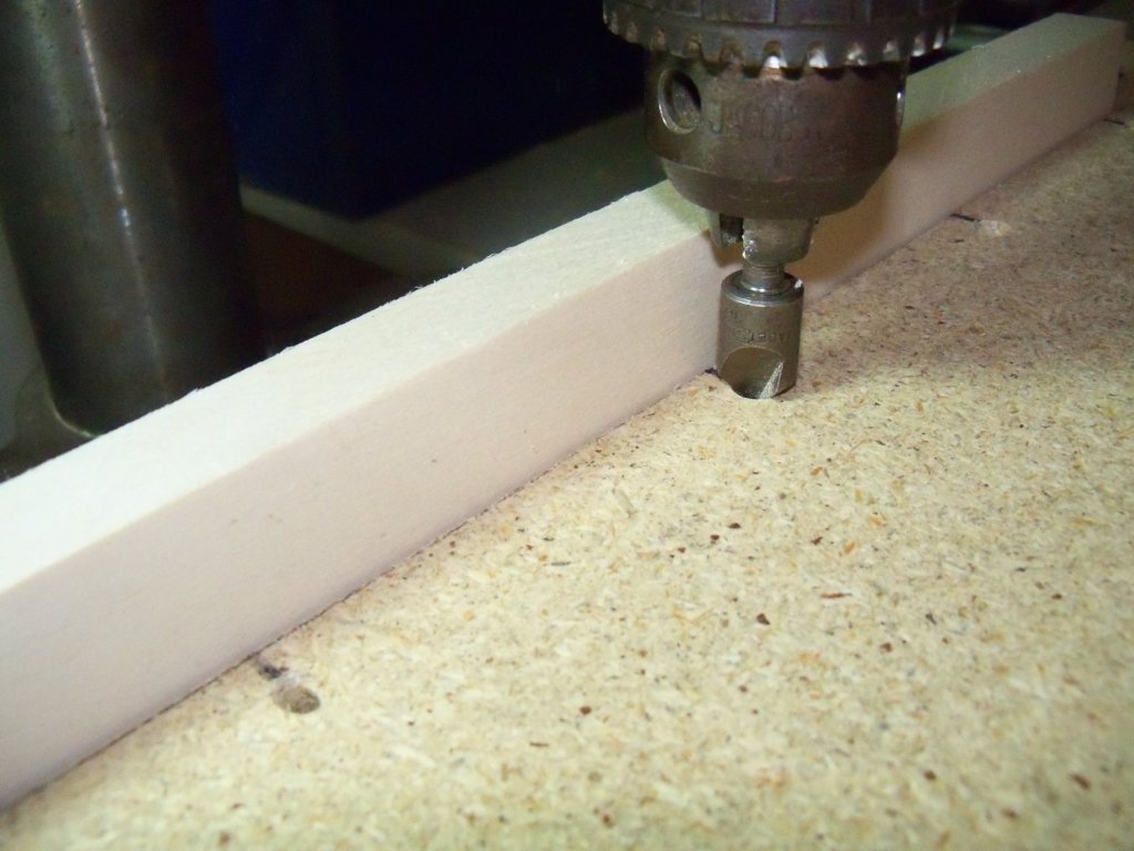
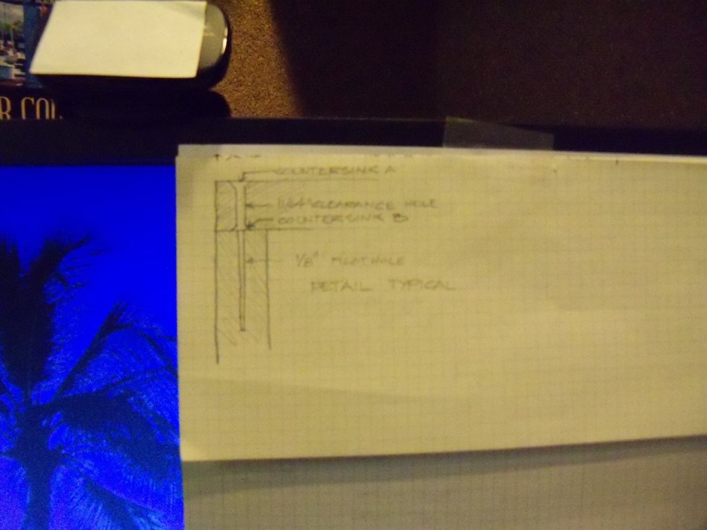
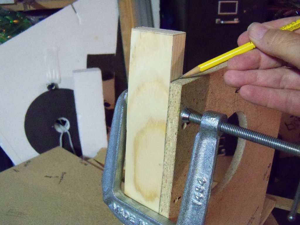
Positioning the fans carefully over the holes, the fan mounting holes were located and marked by firmly tapping a 5/32” drill bit thru the holes on the fan frames into the face of the board. Rather than mounting the fans with screws, I decided to use some 5/32” full threaded bolts about 2 ½” long with washers and lock nuts (as the thin particle board wouldn’t give a regular screw very much purchase) so these holes were drilled clean thru the panels and countersunk on the inside face. All of the panels will be both glued and screwed together except for the top panel to ensure that the air will only be drawn through the filters for maximum fan efficiency. The top edges of the booth panels will have self-adhesive foam weather-stripping applied to seal that joint. I decided to add another upgrade to the original design, rather than screwing down the top panel it will now be hinged to the top of the back panel to allow easier filter changes. The three hinges will need some of the screw holes relocated and the hinge itself will be mounted somewhat backwards to function properly above the weather-stripping as shown in the sketch below. Two latches will also be added to pull the top down tight. So before starting the assembly of the booth, numerous holes needed to be predrilled for all the screws. To be sure that I didn’t forget any holes, the sketch below was made to show the location of all the screw holes needed to assemble the basic frame. As you can see by that sketch, the left and right side panels need five equally spaced holes on the face of the bottom edges to attach to the bottom panel, and six equally spaced holes along the face of the back edges for attaching to the back panel. I used the drill press because the holes needed to be exactly ¼” from the edges and perfectly perpendicular to the surface so that when the screws are driven into the edge of the back and bottom panels it will help them go straight into the center of the thin ½” particle board. With a guide fence on the drill press as shown below, this is easily accomplished. In addition to these holes, the front face of both the right side panel and the baffle needed six equally spaced holes on the front edges at 3/8” from the edge for attaching the ¾” thick front panel which fits between them. Along the back edge of the bottom panel, nine equally spaced holes needed to be drilled ¼” in from the back edge of the bottom panel for attaching the back panel. The bottom panel also needed five equally spaced holes drilled in a line exactly 2 1/4” from the right end starting at 1½” from the front side to attach the baffle. Once all of these holes were drilled, the holes needed to be finished with a counter sinking bit on both faces as shown below. While the countersinking allows the screw heads to fit flush on the exposed front faces, the hidden back faces also need this to be done. That’s due to the fact that when screwing parts together the surface of the part being pulled tight tends to mound up around the screw making it hard to pull the joint up tight. That is especially true when screwing into particle board. The detail shown below shows that the countersinking leaves room for this excess material to mound up without interfering with the joint. Upon temporarily setting the components together with clamps to test the fit of everything including the filters, it became evident that I had made a couple of dumb mistakes. First, when buying the furnace filters, I should have realized that the 14” x 20” x 1” filters were actually labeled on the box in what they call nominal sizes. The actual dimensions of 13 11/16” x 19 11/16” x ¾”, caused some consternation on my part to find a way to accommodate the new sizes without having to re cut everything. Having already revised my design to use 1” vinyl “U” channel in place of the wood and hardboard assembly used in the original design by Don Stauffer in his magazine article, at ¾” the filters would now be a very loose fit. However, with the addition of some narrow strips of 1/8” hardboard glued to the inside of one flange of the channel, the filters can fit a little tighter and still be easy to install with 1/8” of play. Thankfully the flanges of the “U” channel are fairly wide and can help me cover some of the remaining gaps. Having already planned on using two filters butted together in the middle with a strip of tape over the gap, there is a little play there also. The second mistake was that I overlooked cutting the front cover for the plenum. Since I didn’t have any more of the ½” particle board I will just cut it from a scrap of ¾” pine. (The pine is lighter and will provide more purchase for the screws anyway.) The part’s just a 2 inch wide strip approximately 22 inches long with the two ends cut at a bevel to match in with the top and bottom panels. The bevels are important in order to give an airtight seal to the plenum, so I left it at 22 inches until I got the booth partially assembled. Having a little extra length to play with, I marked the bottom bevel directly from the bottom of the baffle onto the bottom of the front cover. After cutting the bottom end bevel, the front cover was just be propped in place to allow marking the top bevel even with the top of the right side panel to help ensure a tighter joint there also. This whole situation just reminded me of a saying used often by Marine Gunnery Sargent Tom Highway (AKA Clint Eastwood) in the film Heartbreak Ridge: “A Marine needs to improvise, adapt, and overcome.” While I’m not a Marine, that quote could still apply here. As a matter of fact that quote was a motto that I readily identified with anyway, thanks (??) to my lifelong adventure (??) with MD. On that note, I think I'll take a break. (To see if I missed anything else.) ------------------------------------------------------------------------------------------------------------------------------------------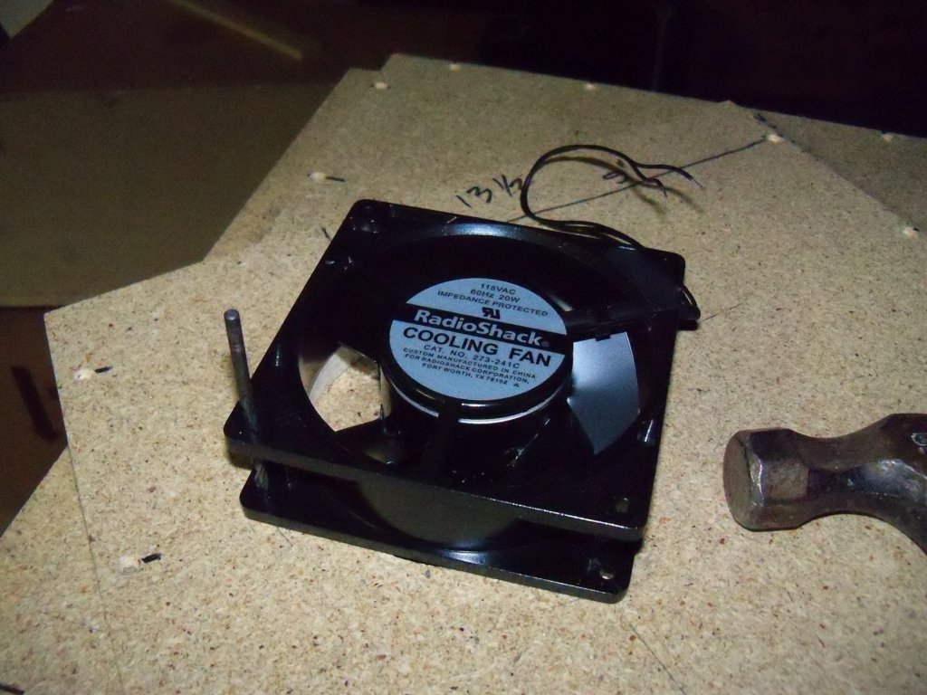
-
Homemade Spray Booth
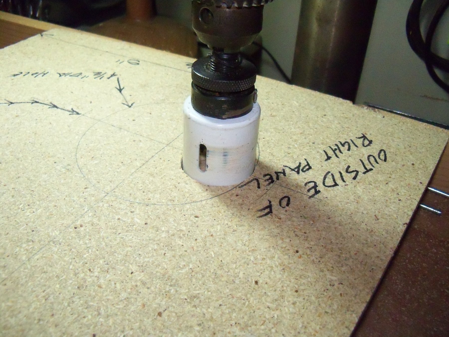
BETAQDAVE replied to BETAQDAVE's topic in Modeling tools and Workshop Equipment
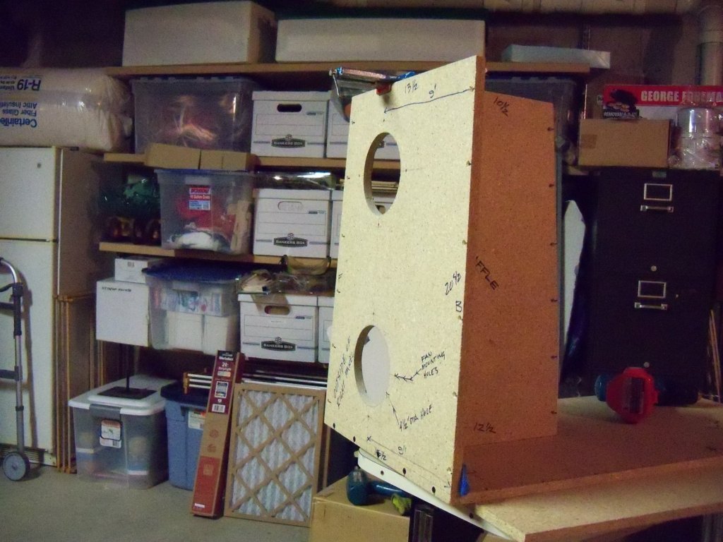
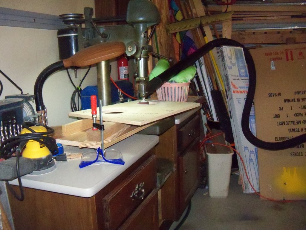
As I said in my last posting, the right side panel first needed to be drilled for the fans. Using a two inch hole saw installed in my large capacity drill press in the garage, I set one edge of the hole saw up against the inside edge of the drawn 4 ½” dia. circle for both fans and cut entrance holes for my jig saw blade. Things seemed to be going smoothly until I encountered the dreaded: You can’t find the right tool when you need it syndrome. Finding my jig saw wasn’t a problem, (since I have two of them) but my package of blades for them seemed to have sprouted legs and run off somewhere. Usually my accessories for my portable tools are stored either in the tool case or right next to it, but there was no sign of them. When this was discovered a house wide search ensued that wasted a good two hours. Looking high and low, the frustration level kept steadily climbing until I finally gave in to the: You won’t be able to find it until you give up and you will find it later when looking for something else altogether syndrome. Oh well, there is usually more than one way to skin a cat. Installing a 3/8” brad point drill bit in the drill press, I proceeded to drill many, many, many (Did I mention many?) slightly overlapping holes around the inside perimeter of the drawn circle until the waste finally dropped out. It made for a very crude hole, but by switching to a two inch sanding drum installed in the drill press it was sanded smooth right up to the drawn circle. You will notice in the photo below my equally crude setup for sucking up the heaps of saw dust created by this operation. Between the house wide search and the much modified procedure, this turned out to be a full day’s work on the spray booth. It felt sort of like trying to make a silk purse from a sow’s ear, but I guess if the end result turns out all right then it’s all good! Hopefully things will work out easier on the rest of this project.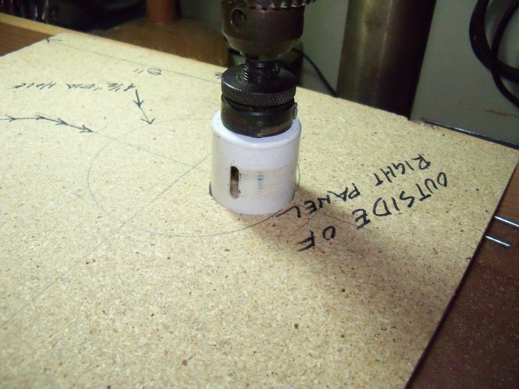
-
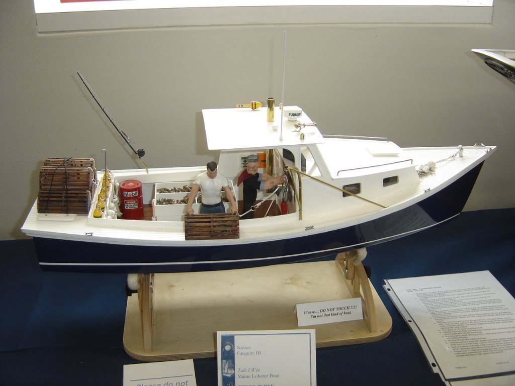
Well Popeye, I see that your avatar was spotted recently at the 43rd Annual Midwest Model Ship And Boat Contest held in Manitowoc WI. Seems like a long way from home just to put in an appearance. That must be Bluto manning the lobster traps.
-
Or another option is for you to die. Most artists works tend to sell for a lot more when that happens, but then the money doesn't exactly do them much good any more. The models that I sold myself ended up selling for just the price of the kit or material. At least that way I recovered that cost, had more room for more models, and had money in hand to buy the next one. That way I had essentially gotten that model and the fun of building it for free!