DONATION DRIVE - SUPPORT MSW - DO YOUR PART TO KEEP THIS GREAT FORUM GOING!
×


allanyed
-
Posts
8,149 -
Joined
-
Last visited
Content Type
Profiles
Forums
Gallery
Events
Everything posted by allanyed
-
Mike, Silk Span is a non-woven paper that is surprisingly robust once it has been painted with artist acrylics. (not the cheap bottled craft paints) If you have not already seen the posts that follow, you may want to check it out. I would also buy a copy of the supplementary booklet on making sails by David Antscherl for $8 plus shipping from Seawatch Books. I find it to be superior to cloth as it is so close to scale and avoids the need to do sewing or stitching which is nigh impossible to do at scale smaller than about 1:12. " Seems" there have been a lot of posts showing sewn sails lately and they really do not look right as they are so far out of scale and take away from what would have been a very nice model.
-
 Haddock I believe the Wasa carried 24 pounders and 3 or 4 pounders thus the size difference in the cannon, the carriages, and the size of the gun ports as well as the distance from the deck to the the gun port cills and ledges. I look forward to how the clay cannon project goes as this is a new idea for me. I can see a clay cannon being made and used to make a silicone mold then casting the barrel in casting resin or pewter which will hold up very well compared to clay, but I still find your idea intriguing and anxious to see the results.
 -
Sorry Dave, I have no idea what the problem is. Perhaps you can contact a moderator for some help on this. Again, sorry I cannot help.
-
Lester, sorry but I am a little confused. I believe the seven pages of plans from Hahn include drawings of each of the stern timbers and transoms as no two are the same. Perhaps you can contact whoever sold you the plans to get the missing missing sheet.
-
Roger, They may not have one digitized or possibly they do not have one at all. I just did a search using the key words ketch, builder and contract with a time span of 1650-1700 and had a lot of hits, but no builder contracts. Do you have names of any of these ketches?
-
John, Very well done build log, thanks for sharing! What is the material you used for the sail and edge seam? Thanks!!
- 9 replies
-
- 1
-

-
- Whistle Blower
- Finished
- (and 1 more)
-
Faring the Frames
allanyed replied to acaron41120's topic in Building, Framing, Planking and plating a ships hull and deck
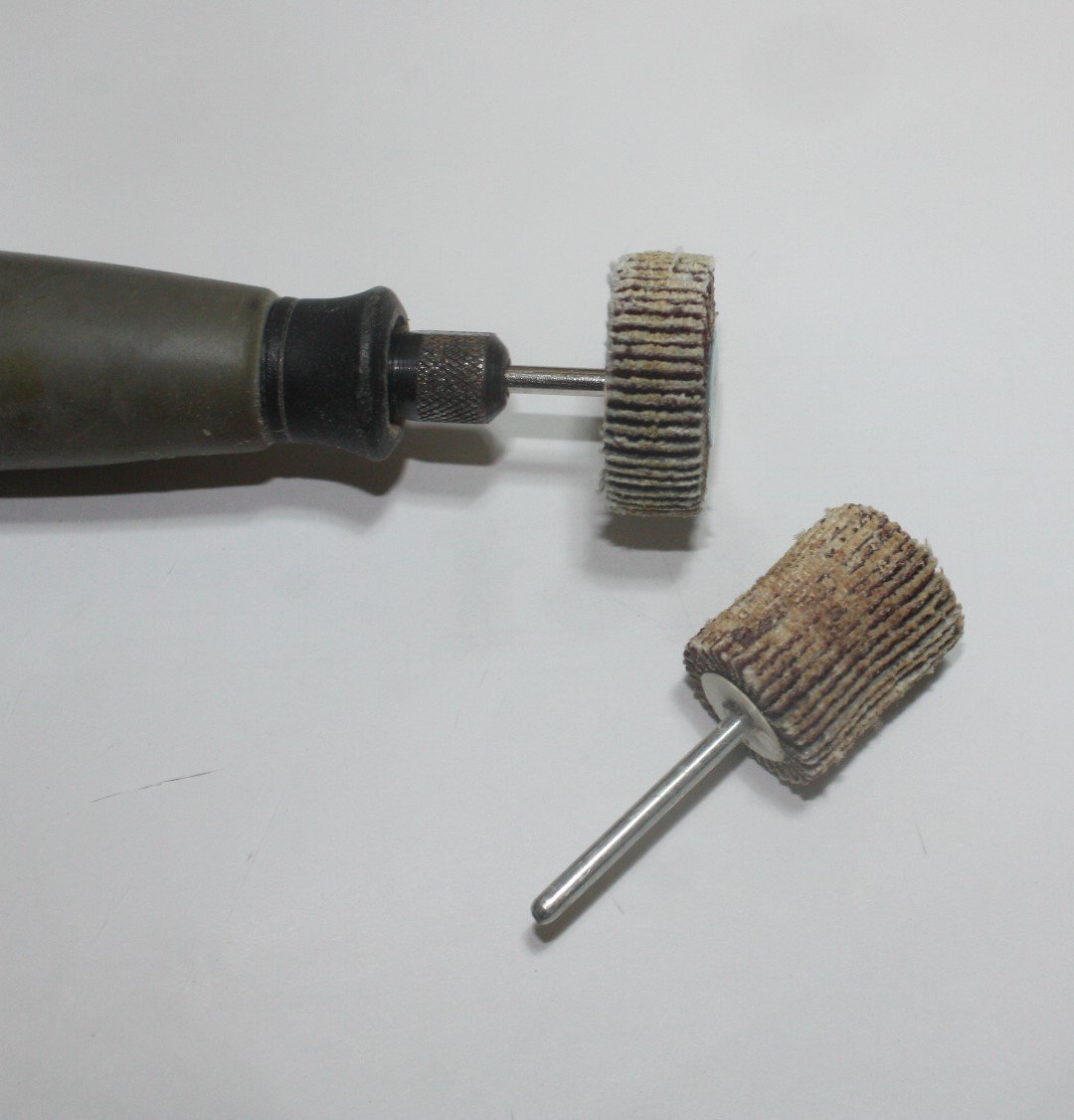
To answer your question about fairing Jaeon, based on my own experience, yes to each item you mentioned but files are not really necessary. I am sure there are many other methods that members here use that work well. You can also add a sanding mouse to the mix. Are you building POF or POB? For POF, the frame drawings should show the amount of bevel along each frame so can fair these CLOSE to the line before installing, then do the final fairing with sanding sticks. If plywood POB, these usually go quickly as the wood is soft so care needs to be taken not to go too fast and over sand. Constantly check the fairing with a piece of plank to be sure there are no dips or bumps. If the assembly is really rough cut and needs a lot of sanding to get the frames faired, a rotary sanding wheel is useful for the initial heavy work. Just don't over do it and know that some finer hand work is best used at the end of the task. If you do use these, safety glasses really should be used!! Photo of what I mean follows:
-
I love seeing a build with machinist squares being used to check that everything is aligned and square. Looking good Maury!!
-
Brett, when you say inexpensive, do you have a budget in mind? For some $25 is too much, for others, $250 is too much, and on and on. For the 18th century, the Shipbuilder's Repository 1788 is a great book to have but it is in the range of $400-$500. If you are looking only for scantlings, you can find copies of the 1719, 1745 and 1750 Establishments in parts of some books including the 1719 Establishment in Goodwin's Construction and Fitting of British Ships of War. This book also has a lot of details on all parts of the framing, planking, decks and so forth for a range of years from 1650 to 1850 for under $100. For armament, furniture and fittings, Lavery's Arming and Fitting British Ships of War is a great book to have for under $100 and covers 1600 to 1815. You can also find the Establishment scantlings and all the scantlings from the Shipbuilder's Repository in Scantlings of Royal Navy Ships for $45 at Seawatch Books which also contains the scantlings from David Steel's Elements and Practice of Naval Architecture, 1805. If you have a specific ship in mind you can sometimes find the original contract, especially if it was built in a private yard. There are hundreds of these available at the National Archives, in Kew, England at no cost if for private use. I don't know how far back they go but I have transcribed a few of these hand written contracts from the 17th century and 18th century that are held at the NA in Kew.
-
For securing seizings, knots, splices, etc. perhaps shellac (pH 7 to 7.3) is the better way to go.
-
Furled sails, to fit or not to fit ?
allanyed replied to Mike Reader's topic in Masting, rigging and sails
Mike How do the sails look? If the scale is 1:75 or 1:98 it is nigh impossible to make cloth stitched sails to scale. As has been brought up in a number of recent posts, at scales from about 1:48 and smaller, cloth stitched sails are way out of scale and ruin what may be an otherwise beautiful model. If you could post some photos with some closeups, I am sure you will get a number of opinions and suggestions on alternative solutions. -
Good information John, I am finding this to be a rather interesting and informative discussion, thanks guys. So will the low pH of PVA, including Titebond at 4 (according to several additional sources) or Elmer's white PVA with a pH of 5, destroy the rigging, or even the wood that we glue together, over time? Maybe it's time to go back to hide glue with a pH of 6.7-7.4, close to, or right at neutral 😁
-
That's the one. Which of the many Resolutions are you building? If it is the Corel kit of the cutter that they describe as 17th or early 18th century the tables are wrong so it should not be used. If it is the Ferret 1711 the table might work, but they do not cover cutters. Sorry this is not cut and dried.
-
From the American Bee Journal: Chemical composition As beeswax is the primary construction material of the beehive, its chemical composition is integral to how the hive functions. This same material, the storage location of food resources and developing brood, must be relatively non-reactive, so beeswax’s neutral pH (7) suits the need perfectly. A product of organic processes, this product is created from carbon, hydrogen, and oxygen—three elements taken from the honey and nectar the bees collect, which are arranged into long carbon chains of fatty acid esters and aliphatic alcohols. These compounds and their ratios vary from species to species, but retain similar chemical properties including a low melting point which, from a human perspective, makes it very useful for sculpting and shaping once it has been harvested and cleaned.
-
Clogger I use a 10" table saw to rip billets that can then easily be handled on my small (3") saw. The waste in the form of saw dust from the 10" saw, if cutting thin sheets, can be as much as the yield of wood to be used. I suppose it can be done, but I feel a lot more comfortable handling small pieces with the 3" saw compared to the 10". If you want to rip small strips, say 1/8 X 1/4, I think this would be difficult as well as possibly dangerous with the big saw. I am curious to read replies from others.
-
Rope-where to go since Syren is no longer making it?
allanyed replied to bear's topic in Masting, rigging and sails
Tony, I know McCaffery and McNarry use wire on VERY small scale models, but for 1:98 and larger it will look like, well,..... wire, not rope. Guess it depends on how much realism one wants to depict on their model and in the end, whatever make the builder happy. -
Rope-where to go since Syren is no longer making it?
allanyed replied to bear's topic in Masting, rigging and sails
Lyle Don't use the kit string if at all possible. Search the many threads here and on the net on making rope. Gutermann and other brands of materials are reviewed and discussed. You will also need to decide if you want to go with cotton, linen, or poly. -
Go to the top of the page and click "More" Then click on "Articles Data Base". Then scroll down to the Masts and Rigging section. Then click on Danny's spread sheet, third one down. Cheers
-
Hi Trond Actually the spread sheet here at MSW is based on Lees' Masting and Rigging. It may be close or the same as Steel for his era, but Lees covers the 17th-19th centuries so helps a wider range of model builders. Both are worth having and checking as appropriate. Used copies of Masting and Rigging are available for under $100, but if one is only interested in the mast, spar and rope sizes without drawngs and details on rigging, the Vadas spread sheet is a free way to go (not including the 1670-1711 time period which as mentioned above is not at all accurate, especially when it comes to the lengths of the masts and spars. For this stretch of years, Lees is a great source.
-
Dave Have you looked at the mast, spar, and rope sizes on the spread sheet here at MSW? It is based on the formulas from Lees' Masting and Rigging English Ships of War book and is quite useful except for the period from 1670 to 1711. An incorrect formula was used on the length of the main mast for this time span so every thing else that follows is wrong. But, from 1640 to 1670 and from 1711 to 1860 all the numbers appear to be correct. Go to "More" on the ribbon at the top of the MSW page, then click on Articles Data Base, then scroll down to Masting and Rigging Spread sheet and click on it and the spread sheet will appear. Danny Vadas did a great service in creating this. I wish someone had Danny's original so the one time period between 1670 and 1711 could be corrected.
-
Papegojan 1627 by mati - FINISHED - 1/48
allanyed replied to mati's topic in - Build logs for subjects built 1501 - 1750
Hi Matt, I just joined your build log party and happy that I did. Your work AND your photography are both first class!!! -
Rick The upper stunsail booms had eyes in each end from 1810 and beyond according to Lees on page 18 of The Masting and Rigging,. On page 118 he describes the hauling in and out of the booms as having two double blocks, one made fast to the outer boom iron, the other stropped to the hole in the inner end of the boom (I assume when there were no eyebolts.) He makes no mention of blocks with hooks, but that does not mean that method was never used. Henry, I am curious about the eyes and blocks with hooks. Can you give your source as this seems it would be a nice alternative if the year is appropriate? Thank you very much.
-
I THINK, without years of research, that the closest I could get to learning those secrets Druxey is to ask Richard Endsor. For anyone wanting to use the Heritage site, it appears that there are only several times it can be used for free without signing up for a basic plan, as I just found out. There is a 14 day free trial though, so have fun while you can. Was fun while it lasted.
-
You beat me to it Druxey. I agree with you completely. Don, it is far easier making one perfect barrel and casting as many as you need for your build. You can cast in metal or casting resin. Silicone molding material is readily available and far easier than using plaster or some other materials and there is no need to make lost wax castings with all the paraphernalia that is required. There are some tricks you can use so there is no need to make two piece molds which invariably leave a seam that has to be filed and sanded off. Making the monogram and vent field are projects in themselves so making these once is an advantage as well. If you decide to go this route feel free to PM me and I can send you information on making your barrels with a single piece mold.
-
This may help as I was able to save to clipboard. https://myhr.tg/14QNa6d4 https://myhr.tg/1LpsmpJl