allanyed
-
Posts
8,149 -
Joined
-
Last visited
Content Type
Profiles
Forums
Gallery
Events
Everything posted by allanyed
-

Are there any decent clamps?
allanyed replied to bigcreekdad's topic in Modeling tools and Workshop Equipment
Big Creek Per the posts from Dziadeczek and Druxey, you don't need clamps. Pre taper each plank, bend by spiling (see the article here at MSW by David Antscherl) or just using heat as demonstrated by Chuck Passaro in his article on forming the bends and there is no need for clamps. If you still want some security while the glue sets, soft wood blocks and elastic bands as Druxey mentioned is a great way to go. If you are worried about dinging the plank place a piece of felt between the block and plank. And if you still want really good quality and versatile clamps, you are best off making your own. Do a search of Ed Tosti's build logs as he uses his own home made wooden screw clamps and may give some details on making these in the logs. If not, he goes into detail on making these in Volume I of his book on the Naiad. You can make them with throats and jaws as small or large as you want. Allan -
Dutch yacht by henry x - RESTORATION
allanyed replied to henry x's topic in - Build logs for subjects built 1501 - 1750
Henry It looks to be a mass produced decorator piece from the mid 20th century but seems to be a nice vintage piece that many folks would like to have. Kit makers spend a LOT of time trying to produce something that will result in a good looking and accurate model at a reasonable cost. Their success varies, but they do work hard to get it right yet affordable. I don't think they would be as inaccurate as this model appears to be so I agree with Wefalck's assessment. Allan -
Welcome aboard Mike. Is this the origin of the screen name? Allan
-
Bonjour Mic!!! Welcome to MSW. It will be interesting to follow a build based on M. Boudriot's work. I hope you will start a build log for us to follow. Allan
-
Dave, I suppose the swifters could have a cut splice or individual eye splices, but Lees states that each swifter, which would be the aft most shroud, would have an eye splice (page 42 of Masting and Rigging of English Ships of War). Also note that the ratlines do not necessarily extend aft to the swifter. If she was rigged as other naval vessels, after 1773 the first six rat ratlines and the upper six start from the second shroud from forward and finished at the second shroud from aft, not extending to the swifter. (Page 44) Allan
-
Dave, The list I gave is if all of these lines are on the ship. Sorry, but I really have no idea which of these would be on a collier, be it as merchant built or converted to RN service so I cannot say if the kit drawings are correct or not. If anyone here at MSW knows for sure that would be great, but it may come down to trust that the Amati folks did a thorough research into the rigging that is likely to have been used, including block and line sizes, and so forth. Two of the things that seems to stand out for some kits are that the blocks looking nothing like they really looked and belaying pins that are larger than bowling ten pins if they were full scale. I don't know if that is the case for Amati kits but maybe something to check before installing. Allan
-
Not sure which lines are appropriate for Bounty, but the general order would be Burton Pendants Shrouds, starting with starboard pair, then port pair, then starboard, etc Swifter Stbd, (if odd number of shrouds eye spliced) Swifter port (if odd number of shrouds eye spliced) Breast back stay eye spliced stbd Breast back stay eye spliced port standing back stay stbd standing backstay port fore topmast preventer stay fore topmast stay These go on after the trestle trees, cross trees, bolsters, cheeks etc are assembled and before the topmasts are put in place. They can be done before the mast is stepped but I have never had a problem rigging these after the lower mast is stepped. Allan
-
You can also make pins from brass rod then round one or both ends with a cup burr. The shank will be the same diameter as the head, but will be inside the part so unseen. Allan
-
GK Not sure this will help but check out the New England Stonington Dragger build log by Fried Clams which has a lot of small parts including nuts and bolts. Model railroad parts suppliers should also be a help. Allan
-
Printing on raw silkspan is not a great idea as it bleeds through. Of course if you want to print something that has a mirror image on the opposite side this is not a bad way to go. For numbers and letters, not so good. If the silkspan is painted with a good quality tubed acrylic paint the bleed through is prevented. The silkspan should first be taped to a frame with a filler plug inside the frame. Wet the span, remove the plug and let it dry and shrink. Put the plug back in place and paint. I like to mix the paint about 2 parts paint to 1 part water and apply two or three coats. Once it is dry and shrinks again, you can draw the sail shape with a pencil, tape it to a sheet of paper and print on your printer. If the sail is larger than an 8.5X11 for US printers, take some scrap painted span and tape it to a sheet of paper and print the numbers. Wet the numbered piece with matte medium and apply to the sail. The medium stays wet for a while so you have plenty of time to adjust it on the sail. Allan
- 8 replies
-
- 3
-

-
- small boat
- sails
- (and 1 more)
-
Welcome aboard!!! For the fishing vessels, I assume you are in contact with the museum regarding plans that they may have. I have had luck in the past getting copies of plans from boat yards as well as long as I committed to not building a full size vessel from them. Looking forward to your build!! Lang may yer lum reek Allan
-
Securing boats
allanyed replied to DaveBaxt's topic in Discussion for a Ship's Deck Furniture, Guns, boats and other Fittings
Eberhard, I agree this book is a must for anyone wanting to have accurate information on ships' boats, but in my copy, page 128 the last page of the book and part of the index??? There are photos of two cutters and a launch stowed on a ship of 1800 and a pinnace on the Lowestoffe (1761) on page 48 of my copy of this great book. Allan -
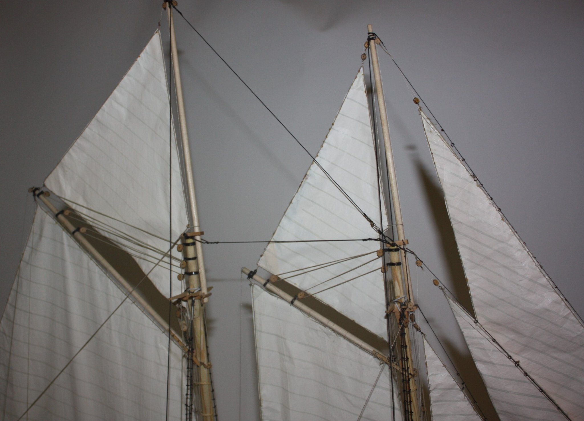
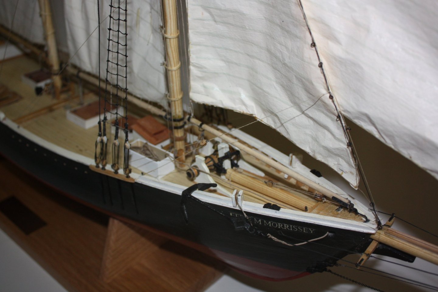
Couple pics as she is today, nearly ready to be packed up and shipped. Top mast hoops are being remade and need to go on and a few little odds and ends.

- 86 replies
-
- 9
-
-
- schooner
- effie m morrisey
- (and 1 more)
-
Securing boats
allanyed replied to DaveBaxt's topic in Discussion for a Ship's Deck Furniture, Guns, boats and other Fittings
Hi Dave, This was addressed in some detail here at MSW a month or so ago. I don't remember the subject name or if a consensus was reached on how the boats were tied down, but you should be able to find the thread using the search box. You may find the following boat information interesting even though your kit only gave you one boat. Keep in mind that if the RN fitted her as they did her rated ships or even her sloops, Bounty would likely have had three boats. Per W.E. May on similar sized vessels, these could have been the launch (which is the type used by Bligh and his 18 sailors,) a pinnace or possibly a cutter over 20 feet, and a 16foot or 18 foot cutter. According to an article by the Pitcairn Islands Study Center of the Pacific Union College, Bounty had a launch, a cutter, and a jolly boat. The term jolly boat was mainly used for small light weight boats of the 17th century but came back into use in the latter part of the 18th century and was used to describe small boats of 16 feet or 18 feet, probably cutters. (Lavery, Arming and Fitting, p. 223) A bit of contradictory information on boat types to be sure, but at least there seems to be agreement that there should be three boats which would complicate your concern on how they are tied down. Allan -
Looking at some assumptions.... 91 feet over all, thus about 90 frames if on 12 inch center, including the space between frames which may be as much as 2" I have never seen framing disposition drawings of a collier but surely there was some space between many if not all of the frames. If the frames are made out of scale at 12", there would either be no room for the space between frames in order to wind up at 91 feet, or, if the 2" space is maintained with the 12" frames, the hull would be about 15 feet too long which would lead to problems in making the keel the correct length, beam locations, deck furniture and mast locations. Even if the space was cut down to 1" the hull would still be over 7 feet too long. 5.3mm (.208") is not so hard to do but not with just a saw. You can cut boards to something more than 5.3mm then use a thickness sander or carefully set a planer to yield the thickness you want. Same thing can be done when cutting wood for things such as beams, bottom planking, wales, quickwork, deck planks and so forth. Allan
-
Dan, I checked a couple articles and there seems to be a consensus on a few things such as using tight weave (high thread count) cotton, fabric paint or acrylics with fabric medium added, prewashing to make sure any sizing from the factory is removed and a few more. Do a search for "painting cloth" and you will get some good information on freehand and stencil type applications. One pretty complete article is at https://www.thesprucecrafts.com/fabric-painting-tips-2578184 Allan
- 8 replies
-
- 3
-
-
- small boat
- sails
- (and 1 more)
-
Brass rings for rigging on HMS Bounty
allanyed replied to DaveBaxt's topic in Masting, rigging and sails
Bob, I have tried the sawing method and it does not work for me. It removes metal which in the end changes the diameter of the ring, abeit not much, but enough that I then need to always have to figure out the size of a larger rod size to compensate, etc. When I snip each ring I intentionally do so at an angle as this leaves the beveled edge you mention which I want because it yields more surface area for the solder. Whatever works in the end, right? What I really want to know is if there is anything out there that will blacken solder as well as brass and/or copper. Allan -
Great question. I have used high thread count cloth in the past depending on the scale of the model and would love to see that article if anyone can steer me to it as I never added lettering or numbers. Sorry I don't have an answer on the numbers application. You could silkscreen the numbers but that is a lot of work to set up for a only a couple passes. If you were using silk span it would be an easy solution in that you could print right on the sail with a stencil and paint marker or colored artist pencil, but for cloth, not sure these would work very well. Hope someone has a proven solution on this one. Allan
- 8 replies
-
- 2
-
-
- small boat
- sails
- (and 1 more)
-
Brass rings for rigging on HMS Bounty
allanyed replied to DaveBaxt's topic in Masting, rigging and sails
I use a soldering gun with this solder. Gas torch is great for silver solder but this paste has a very low melt temp and a torch could blow the solder off the part. I literally hold the trigger on the gun for 10 seconds and it does the job. Allan -
Brass rings for rigging on HMS Bounty
allanyed replied to DaveBaxt's topic in Masting, rigging and sails
Dave, I have gone from brass to copper when possible and making copper rings or eye bolts is quite simple actually. For rings, wrap an appropriate diameter UN-coated copper wire around a drill bit, the OD of which is the same as the ID of the rings that you need. I usually give about 10 or 12 wraps then remove from the drill bit and you will have a spring of sorts. Then with small snippers cut individual rings. Close the ends with small pliers or even your fingers so they are touching and then soft solder the joint. I like to use soldering paste for these tiny pieces rather than pieces of hard solder. Easier to apply to the joint without putting on too much solder. Once this is done they can be cleaned up with acetone or pickling solution and painted. You can blacken them with liver of sulfur as well, but it will not blacken where there is any solder on the wire based on my experience. If you can manage to keep any excess solder off of the ring, or clean it off after they are made, you can then blacken them while they are in place with liver of sulfur (for copper, not brass). See Ed Tosti's Young America build log as he gives good detail on copper work and using liver of sulfur. If the application calls for a ring in an eyebolt, make the rings and solder them, insert into the eyebolt before closing and soldering the eye, then close the eye and solder the eye. Allan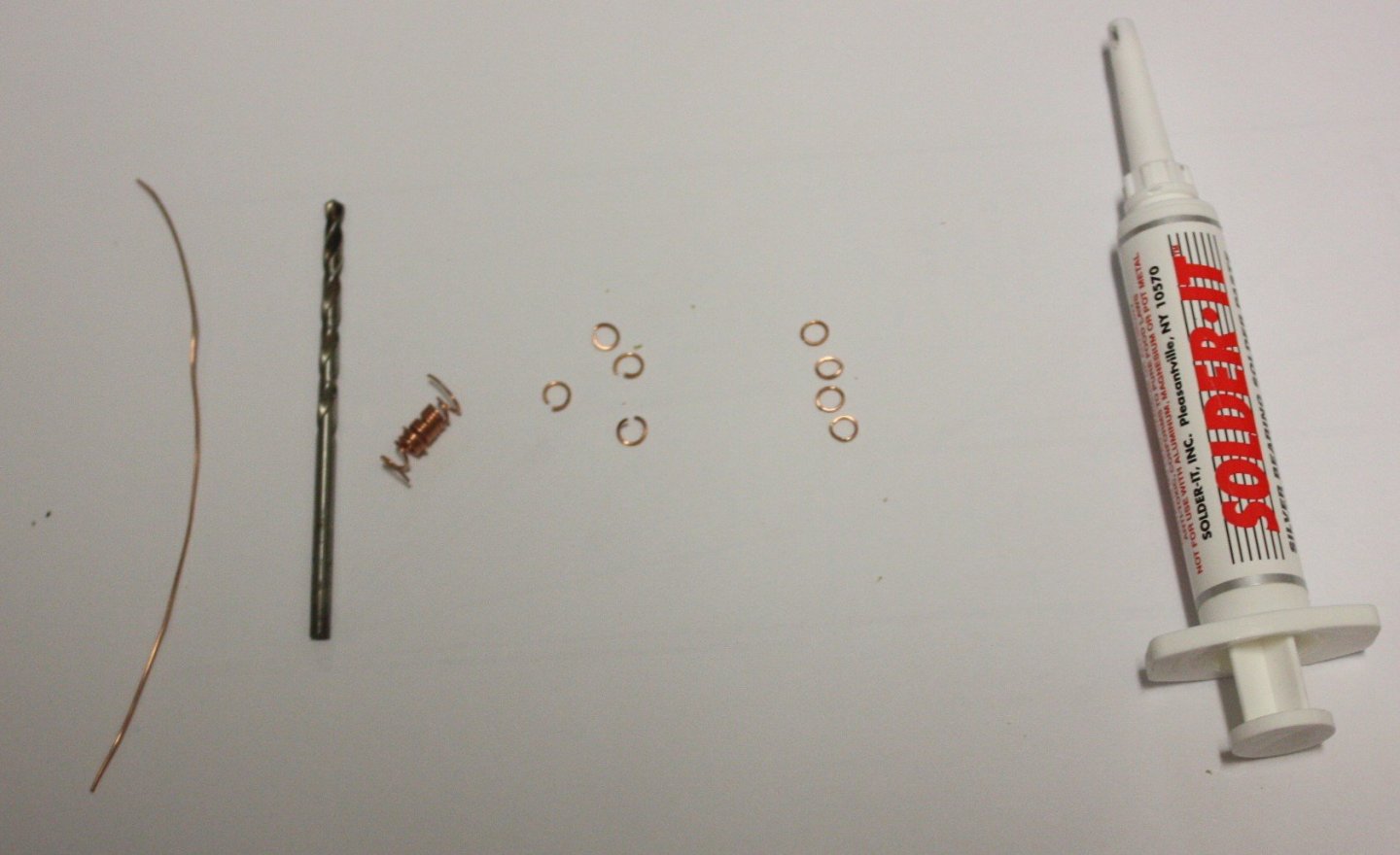
-
Lofting cant frames
allanyed replied to Don Case's topic in Building, Framing, Planking and plating a ships hull and deck
Don, For a good start, you might benefit from reading Wayne Kempson's article here at MSW on drafting, which includes square and cant frames. https://thenrg.org/resources/Documents/articles/DraftingShipPlansInCAD.pdf Allan -
Brass rings for rigging on HMS Bounty
allanyed replied to DaveBaxt's topic in Masting, rigging and sails
Hi Dave Are you talking about eyebolts or rings? Allan -
An alternative is to spend the money on supplies that are starting to disappear and consider scratch building for a number of reasons from historical accuracy, the pleasure of researching and possibly working on drawings as needed, and the satisfaction of having built something that few others, if any, have ever built before. The money for a good quality kit will pay for a lot of materials and the occasional new tool. Even materials such as Castello, European box, holly and some others are getting harder to find and more expensive than ever. When I get the FOMO feeling I look for wood and tools and it feels like my birthday every time they show up at the door!! In the end, choose the route which will make you happiest. Some people spend hundreds or thousands on stamps or coins that will only be looked at once in a while and certainly never used, so doing the same with a kit, or supplies even, is really not so different. Allan
-
George Are the pictures of the smaller vessels with the name on the transom contemporary paintings or modern pictures? The reason I ask is that other than vessels in modern times, the only time there would have been the name on the stern of the vessel of the RN was between 1772 and 1782, started and stopped by order of the Admiralty. I assume your project is for the schooner Whiting 1805 so she would not have any name on the transom. Allan
-
Hakan I did bring up the point of the swinging door to the head with the yard along with a couple other places where a standard size wheel chair would not fit or be able to easily maneuver. This yacht is literally still on the drawing board so some design changes will definitely have to be made before construction actually begins. It is my understanding that for now the model is strictly for showing prospective investors what she will look like and the concept of having wheel chair access. Allan