allanyed
-
Posts
8,149 -
Joined
-
Last visited
Content Type
Profiles
Forums
Gallery
Events
Everything posted by allanyed
-
 Graham, Your decision to give it a go is a very good one. Once you have done this one time you will have a good understanding. The tutorials should help you a lot on marking out the widths at each frame/bulkhead. It is as simple as taking a piece of card and holding against the bulk head from top to bottom to get the full length, then dividing into the number of strakes of plank to go on to get the width. Little errors can be corrected on subsequent planks. Allan
 -
Dan is correct in that the planks need to be tapered at the bow plus they need to widen at the stern. If this is a two layer model the first layer does not to be done this way but makes very good practice for the second layer of planking. If the planking you show is the only layer it should be taken off and started again. You will need to figure the number of strakes then mark the spacing at the stern, midships and at the bow plus a number of frames in between then use these to have the width of the plank at the various points. Study the planking tutorials here at MSW for details on doing this. The tutorials by David Antscherl and by Chuck Passaro are extremely helpful. Allan
-
Phil, Note that Chuck has posted here at MSW that Syren is no longer making and selling rope. Allan
-
If the glue is CA, try a good soaking/rubbing with acetone. This may even loosen the joint so you can replace the piece and replace with a new piece and glue with PVA which is easier to clean up with water while wet or alcohol once dry. Allan
-
Mike, About which schooner/year/nationality are you asking? Allan
-
Phil Great job on the spread sheets!!!! I have no idea if these are appropriate for the Dutch fleet but lacking other information these could be a big help for Marcus and many others of us. If the Dutch ship on this thread is set up with similar sizes as the British, your spread sheet looks to be very close. For other sizes and eras it should be noted from what I can find in Lees other multipliers should be used. The 2.23 multiplier applies to all rates from 1773 to 1794. This is very close for the 1639 time frame of Marcus' ship which would have been 2.24, at least for British ships. Calculating the mast height, depending on time period and rate, was sometimes based on the beam, keel length, lower deck length and depth in the hold. Differences, depending on rate and era could be as much as 8 feet or more for the same size ship. Allan
-
Vertical planking
allanyed replied to allanyed's topic in Building, Framing, Planking and plating a ships hull and deck
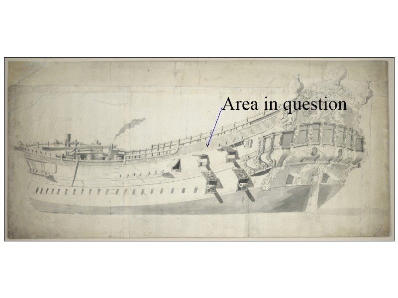
The following is part of an email I received earlier today after going over several oddities regarding the Charles Galley with Richard Endsor. I had also asked about the the extra gun ports on a draught from NMM that does not coincide with the Van De Velde drawing or the gun establishment at that time. Allan As I remember the extra gunports were added to the gundeck following criticism by Henry Sheers. The odd vertical lines shown by V de V on the Charles Galley are probably a result of her poor and very lightweight construction. The toptimbers are probably exposed with board filling the gaps between. That is my best guess. -
I have been starting a little reading in Richard Endsor's book The Master Shipwright's Secrets and came across a drawing by Van De Velde the Elder of the Charles Galley 1676 a 32 gun fifth rate. Between what I think would be the drift rail and the sheer rail appears to be vertical planking of some sort or perhaps balusters. If this is planking I doubt that this would be the only planking as many pieces would be in the space between top timbers so my question is, would this be a decorative laminate, balusters or something else that goes over the planking that would normally be in this area? I would be grateful for a chance to see or hear of any other contemporary information from members regarding this feature. TIA Allan
-
It has all been said above, but I want to add my congratulations on a job superbly done!! I hope to see a new project by you here at MSW in the very near future. Allan
- 1,035 replies
-
- 4
-

-

-
- royal katherine
- ship of the line
- (and 1 more)
-
Edward First - Welcome to MSW!!! USUALLY the standing rigging is dark brown or close to black and the running rigging tan or beige. To figure the line diameter, wrap the line around a ruler for an inch and count the number of wraps and divide into 1 which will give you the diameter. There are very few rigging line suppliers available anymore so you may have to just go with thread that is close in color and size from your local fabric store or look on the internet. You can try to contact the kit manufacturer as well. As you are new, making your own rope may not be something you want to get into,,,,,, yet. Allan
-
If this was a British vessel, the ratios of the ropes all wind back to the masts which wind back to the size of the ship. Lacking better information, these ratios for all the lines on your vessel can be calculated if you choose to use the information for British ships. You can use Lees' Masting and Rigging tables as well as look at the chart available here at MSW prepared by Dan Vadas which was based on Lees ratios and will give you the rope circumference of every line. Be aware though that Dan's information is the same as Lees for ships after 1711 but he used the wrong formula for the length of the main mast for earlier ships thus all subsequent sizes for spars ropes, etc. are not accurate. Still, at model scales the rope sizes may be quite close to what you need. Allan
-
George, I am pretty sure the vertical dashed lines are the edge of the frames that extend up to the cap rail, these frame top timbers forming the sides of the gun ports. The planks between the ports are indeed short pieces of thin quickwork. The horizontal dashed lines look to be nothing more than decorative wooden caps over the ports in place of having the cap rail run continuously over the ports which was common. Allan
-
Druxey When there are both internal and external expansion drawings on the same page, do you know if the top was internal (facing left) with starboard planking and the lower external also showing the starboard side (pointing right)as the standard presentation? Example of the HMS Squirrel can be seen at https://collections.rmg.co.uk/collections/objects/83495.html Thanks! Allan
-
Sorry Michael, but HMS Hawke indeed appears to have planks at the bow from 6 feet to about 8 feet long. I assume the draftsman had the proper information and that these lengths are correct, but hopefully a member will be able to resolve this for you if the drawing is incorrect. I don't know if there was any rule on any plank on a given strake regarding minimum length. There are no hull plank length dimensions given in the Establishments, Steel, or the Shipbuilder's Repository. Allan
-
Michael, Look on the RMG Collections site and you will find plank expansion drawings. You will see the butt patterns for both external planking and ceiling/sealing planking on a number of ships. https://collections.rmg.co.uk/collections.html#!csearch;searchTerm=plank_expansion Allan
-
I take it that they give two pieces as the top of the mast should be square versus round. While the top portion was often cut square it started with round stock rather than being an add on. You may want to try starting with square stock and the forming an octagon with a small plane, then rounding the entire length. Then with hobby knife, chisels, files and/or sandpaper, whatever you have in your arsenal, form the square section. To simplify you can use a 1/4" or 6mm dowel that matches the entire length you need and cut/file/sand the tapered square section at the top. The round portion will also have to be given flats on the port and starboard sides for the cheeks and/or hounds. Allan
-
Tom If you go to the National Archives, Kew, England website, you can try to do a search or email them. They also have an online tutorial on how to read these old documents as the lettering, wording, punctuation and grammar are not necessarily the same as they are today. They have contracts for such things as ships' boats to rated vessels. As mentioned earlier, the contracts were typically only given to private yards. If you wish to build a model of a vessel built in a King's yard, there is likely no contract. Depending on the time period, these vessels would have been built to the Establishment scantlings for that particular time which are readily available from the 18th century. I do not know of any detailed information on scantlings for the 17th century so have opted for ships with contracts when researching potential 17th century projects. The books by Endsor will have answers to a lot of your questions for the 17th century. Allan
-
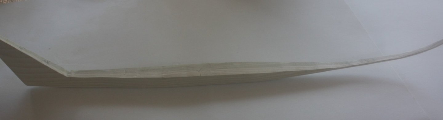
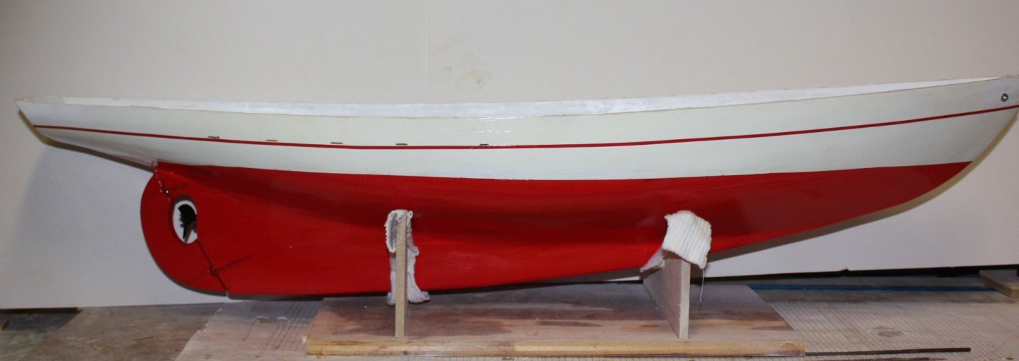
Assuming this is not a pond yacht, but rather a static model, you can go to your local HD or Lowes or any lumber yard and pick up a small piece of poplar for $1 or $2. It can be shaped as easily as basswood. I used this material for a rather complex schooner keel with no problems. As it will be painted using bass wood or poplar should not make any difference in the final appearance. Below is the keel for Boothbay65 before installing and afterwards with painting done. Allan
-
Making frames
allanyed replied to Don Case's topic in Building, Framing, Planking and plating a ships hull and deck
Don, Do you have CAD software? If you do, and if the station lines on the body plan coincide with a frame, you can trace each station line then loft each frame in between the stations and print them out on separate pages. It requires lots of ink and paper, but something to consider for accuracy. Allan -
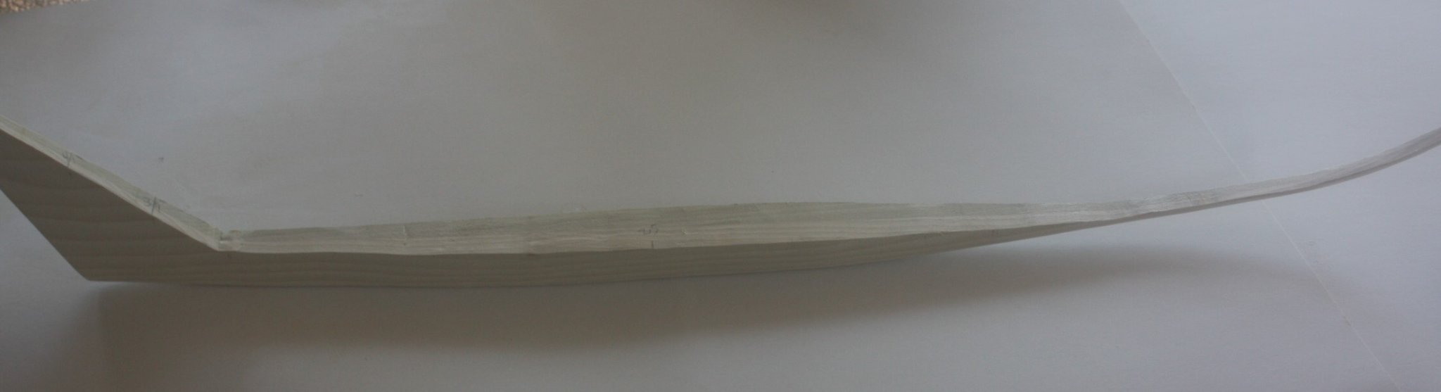
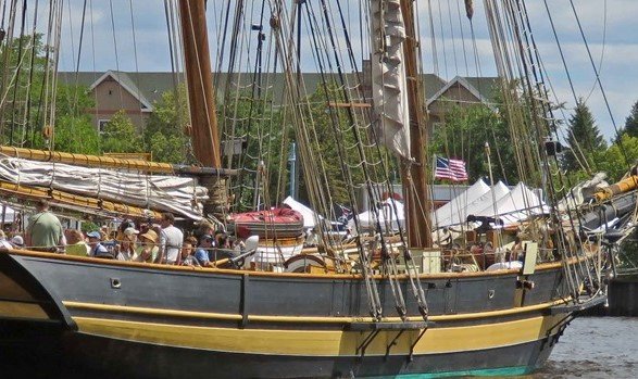
Paul, CA cannot take shear stress very well so is a bad choice (my opinion only - I know there are proponents of CA who swear by it where as I swear at it) You can drill and use brass rod for pins in addition to wood glue. Rods are available to 0.01 diameter and smaller. I would smear a bit of epoxy on the pins when inserting in the channel and the hull as it will give you working time and is incredibly strong. I would also use carpenters glue on the wood surfaces as it will cure quickly and hold everything tight while the epoxy cures. You mention the channels gluing to the wales. Channels do not typically get attached to the wales but rather would be just below or just above the wales. The photo below of the modern P of B shows that they are not attached to the wales. Allan
-
Roger B. Taney rigging and sail plans
allanyed replied to captpjn's topic in Masting, rigging and sails
Jim STRONGLY suggest you edit your post and remove your email address as you will likely get spammed from outside MSW. Members can send you private messages which will go to your email without divulging your email address or theirs. Allan -
Making frames
allanyed replied to Don Case's topic in Building, Framing, Planking and plating a ships hull and deck
On one hand, you can always remove material if you left too much wood but you can't add any. On the other hand, you can cut CLOSE to the line but not quite touch it. Keep in mind that the LINE is the widest point, taking into account the bevel if any so there is a lot of sanding, especially fore and aft where the bevel is severe. How are you transferring the lines from the body plan to the wood? Tracing is not the best way as you can wind up following the grain at times. Printing the futtocks, floors and top timbers onto paper then gluing to the wood works well as you can have each piece run with the grain. Even easier is to print the parts (and number each piece) on label paper. Cut the paper parts out, again, outside the lines, and stick on the pre thicknessed wood then cut them with a scroll saw. Allan -
Are there any decent clamps?
allanyed replied to bigcreekdad's topic in Modeling tools and Workshop Equipment
Roger, Based on looking at various information on PVA glues recently, the following is my understanding. The glue thickness is critical to the strength of a joint as much as the clamping pressure. It's a function of how well the joint is prepped and how snug and uniform the joint is held together while it begins to cure. The glue line should be about as thick as a sheet of paper or a LITTLE thinner. Too thin from clamping too tightly will starve the joint and it will be weak. The more the clamping, the weaker the joint. By the same token too much glue will also create a weak joint and the weakness grows with the thickness of the joint. So, as with many things in life, too little or too much are not desirable. Sort of like Goldilocks, it needs to be pretty much just right!! I cannot argue this point scientifically as I am not a chemical engineer but I have never had a piece of pre bent wood separate using PVA and finger pressure to hold the pieces together for 30 seconds to a minute as there is enough initial tack to hold the pieces nicely. Obviously I do not have hundreds of years of history, but as to pieces coming apart so far so good 😀 I recently saw a model that I built in the late 1970s and it looks the same as the day I finished it. By the same token there almost always seems to be a few areas that need coaxing with clamping. Unfortunately it seems these are most often in a position where a stock store bought clamp cannot fit so elastic bands and home made devices come into play. Allan -
Huge topic Helli!!! Maybe a bit less daunting if you choose a time period and nationality to work on for a start. For me personally, researching a vessel is as much fun as the build so I look for projects in which I can find a few ships for which I can find a list of their captains, voyages, battles if military, original contracts if built in a private shipyard, and so forth. When Wayne Kempson and I worked on the Euryalus books, we wound up with about 30 pages in the first volume on her history from her build at Buckler's Hard, to her master's log while at Trafalgar, to her proposed duel with an American ship during the War of 1812, to her time as a prison hulk for boys. We even found a series of letters sent from one of her officers to his family while he was aboard and a note from Nelson to the Euryalus' captain at that time. Allan
-
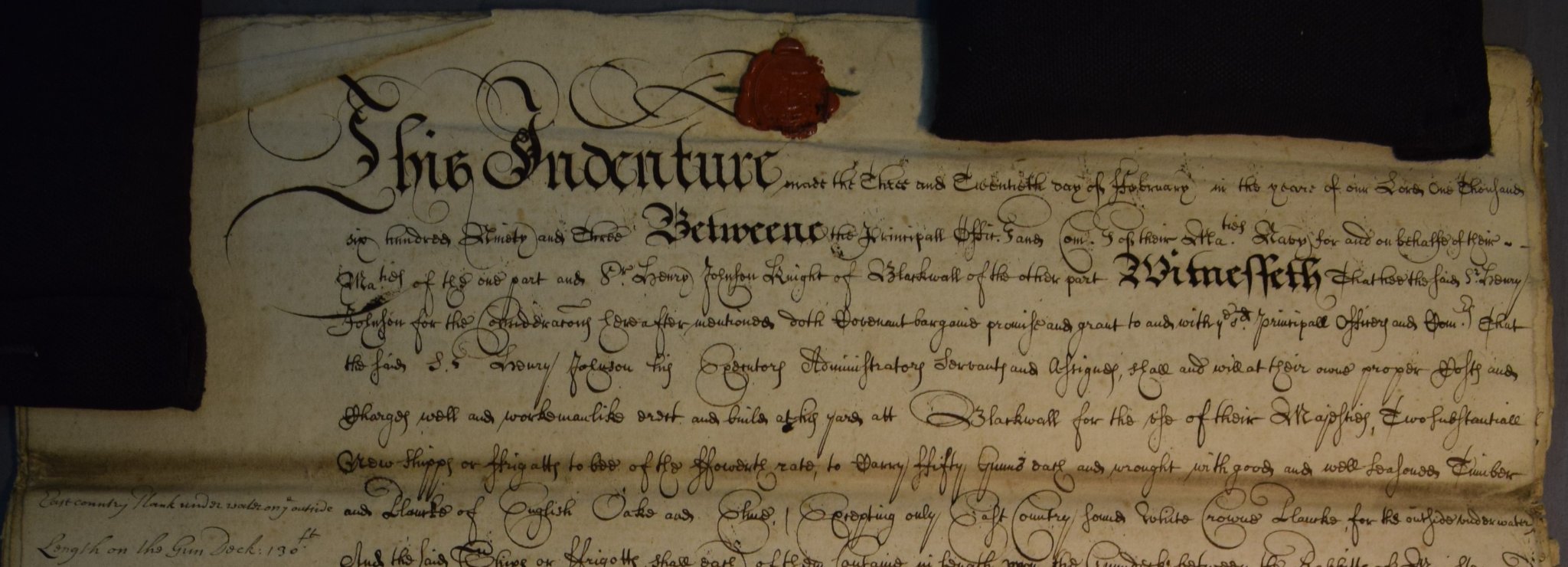
Tom These are repeats of the above, but considering your time period of interest, I reinforce these for being considered for your library. Others may also apply. The Rigging Of Ships: In The Days Of The Spritsail Topmast, 1600-1720, Anderson, R.C. The Masting and Rigging of English Ships of War, 1625-1860 by James Lees NB: I would forget about Rigging Period Ship Models for your particular project, as it is specific to one rate of vessel in one time period in the 18th century. As your interest is 17th century, Richard Endor's books are a must for information from the keel up, including both The Restoration Warship and The Master Shipwrights Secrets. Also consider acquiring a few appropriate original contracts from the same time period once you have selected a ship to build. The following is a portion of page one of an 8 page contract for two fifty gun English ships in 1693. Transcribing these is fun and very challenging project in itself. Allan