


allanyed
-
Posts
8,149 -
Joined
-
Last visited
Content Type
Profiles
Forums
Gallery
Events
Everything posted by allanyed
-
Heck Rick, my new education happens nearly every time I get on this website, thanks to so many of our members. Allan
-
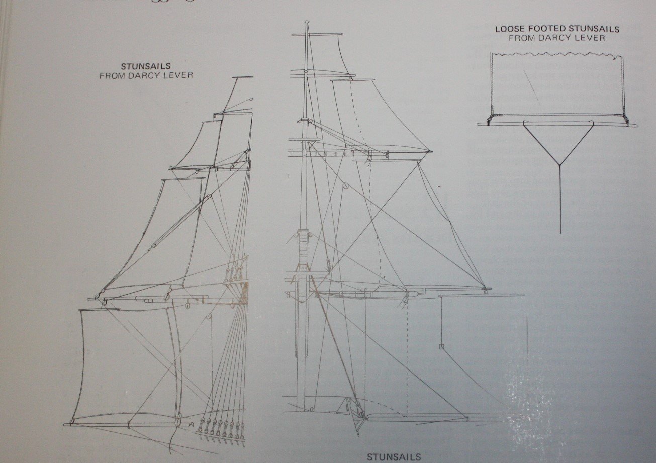
Phil, Sorry to disagree, but according to the following drawing from Darcy Lever, loose footed stunsails had a lower yard or boom rather than the opposite. I may be misinterpreting, but this is my understanding based on this drawing. I believe the loose footing refers to the fact that the bottom of the sail is secured to this stunsail yard or boom and this yard is then secured with the guy line shown. The loose footed stunsail yard had no tack but had a span fitted to each end of the yard and the guy was made fast to the middle of the span by means of an eye seized in the center of the span. The guy was taken aft, led through a block lashed in the main chains and then led inboard via a gun port where it belayed to a cleat. In reading further, I don't believe the topgallant stunsails were ever loose footed though, so a moot point regarding loose footed or not. Rick, The drawings show the rigging which I hope is a help. Lees describes the rigging of the topgallant stunsail as follows: <Assuming the topgallant stunsails were not loose footed,> The halliard was bent one third along the upper yard and rove through a jewel block seized to an eyebolt in the end of the topgallant yard, up through a block stropped to the head of the topgallant mast, and then down and made fast in the lower top. Sheets were double with the forward one leading to the quarter of the topsail yard, the after one taken to the fore top and made fast to the topmast shroud The tack rove from the outer clue, through a block or thimble on the end of the stunsail boom on the topsail yard, and were taken to the main chains up to 1815. Note that after 1815 they went through a block seized to the foretop and down to the pin rail by the fore shrouds. The downhaul was made fast to the outer stunsail yard arm, and then taken to the fore top leading aft of the stunsail. Allan
-
Rick, Stunsails of the fore and main topgallant were introduced in about 1773. They would have a halliard, tacks, and downhauler. (Lees, Masting and Rigging page 118). If they were loose footed there would be a yard secured to the foot of the sail by the two lower cringles. If they were not loose footed, there would be no lower yard. Darcy Lever shows details in his drawings, also shown in Lees (page 116), showing both loose footed and without the lower yard on the stunsails. My apologies but I have no idea if Victory had loose footed stunsails or not. Allan
-

Royal Caroline rigging lines & blocks
allanyed replied to rvmer2's topic in Masting, rigging and sails
Hello Paul, I assume this is a scratch build as I think kits include rigging materials. These days the best blocks I know of are from Syren but you will have to know how many of all the various sizes that you need before ordering. If it is a kit, which manufacturer, Mantua or some other? I can't think of anyone selling rope anymore. Hopefully some members will have a source for you and the rest of us. Kit manufacturers supply rigging line but some of them just use different size string rather than miniature rope so not sure that would be a very good source. Allan -
Blacken-It was always my go to blackening chemical. I finally ran out of it and cannot find it anywhere. Why did they stop making it? For brass I tried JAX and IMHO it is not nearly as good. Pickling and cleaning, burnishing, etc and it still has flaking problems. I love using L.O.S. for copper, but does not work on brass. In doing a little research I found Caswell plating and Caswell Antiquing-Metal finishing products with a chart for their various chemicals for steel, stainless steel, copper, brass, bronze, silver, aluminum and nickel. Some cross over for brass and copper. Has anyone in our illustrious group tried it? https://caswellplating.com/metal_finishing_solutions.html I cannot find the chemical ingredients for Blacken It in order to compare if they are the same or at least similar to the Caswell products for brass and copper. I just ordered a bottle of Birchwood Casey to give it a try on brass. If it is as bad as JAX I will try the Caswell product, especially if a member has tried it and gives it some praise. Allan
-
Eberhard, I could not get it to open. Thanks Allan
-
Maury, As a lover of schooner models, I hope to see your build log soon!!! Allan
-
Keith, Any possibility you could please move to SW Florida and give classes? I would be your first student, and probably the oldest as well. Allan
-
Dying/coloring rope; sources for purchase of quality rope
allanyed replied to Tomculb's topic in Masting, rigging and sails
Closehaul My sincere apologies if this comes across poorly, but is the material in the photo what the kit supplies? The reason I ask is that it is quite different than rope. You can see samples of rope from Syren (photo below) or any rope made on a rope walk thus my question. Beeswax may knock down the fuzzies, but it will still not look like rope. I hope someone comes up with a source for rope as I have pretty well concluded that otherwise I will be learning to make rope myself in the future. Allan -
Susquehanna, Did you PM Deperddussin? It is over four years since his/her post on these craft so he/she may not be checking this thread. If you look at his profile you will see that he has not been on this site since early February. If he does not respond to a PM you might try contacting the Smithsonian Institute Archives where he indicated they have the plans. With the pandemic continuing, it may be difficult to get a response to an email from the SI but you could call them to find out if the archives are operating in any semblance of normalcy. Their phone number in Washington is 202 633-5870. Allan
-
If you don't want to soak the wood with CA (I am swooning just thinking about the foul fumes) try using a different wood such as castello or true boxwood (if you can find the latter). You can buy small blocks of castello for a reasonable price at Gilmer Woods. Swiss Pear will work as well if you want a reddish color. Allan
-
Cant frame R+S
allanyed replied to Don Case's topic in Building, Framing, Planking and plating a ships hull and deck
Hi Jaager, To add to your comment about the R&S not always being related to the stations, in addition to Saint Phillippe, Litchfield 1695 frame locations and R&S for one more example have no relation to the station lines. I have seen others as well where R&S does not necessarily have any relationship to the distance or location between the station lines. You are of course right about there being reduced siding on the frames parts but I wonder if it really had anything to do with lack of lumber? I don't have any idea when the timber shortage became an issue but reduced siding dimensions are shown long before Steel, going back to the 1719 Establishment and even further. Looking at several contemporary contracts, including Lark 1702, Romney 1693, Severn and Burlington 1695, and James Galley 1676 they specify siding dimensions of the floors, futtocks, and top timbers and they are reduced even more than shown in Steel and the Establishments. Allan -
Cant frame R+S
allanyed replied to Don Case's topic in Building, Framing, Planking and plating a ships hull and deck
????? Not sure what you mean where the planks go?? -
Number of floor timbers
allanyed replied to Don Case's topic in Building, Framing, Planking and plating a ships hull and deck
Steel is not written in stone Don. Steel came out in 1805, and Discovery was launched sixteen years earlier. The only thing I can find in Steel with 28" R&S is an 18 gun sloop of war which he shows in the scantlings as having a length on the GD of 108 feet. The Shipbuilder's Repository of 1788 shows the GD for this size vessel as 98 feet 5 inches, much closer to Discovery and subsequently a R&S of 2 feet 0 inches. Just curious, but how did you come up with 28" for the room and space? Allan -
I only speak from recent experience in working with silkspan for sails, so not sure this is a great idea. Tape the silkspan to a stretcher frame and then wet it thoroughly and allow to dry which will shrink it tight. Then paint while it is still taped to the stretcher frame. Use whatever the color that you want using a good quality tubed acrylic artist paint. I like to thin it with one part water to 3 parts paint. It will sag but then retighten when dry. Once dry, draw the shapes you need and cut the pieces and cover the boat. Once covered as reasonably tight as you can without tearing, (it may have few wrinkles) and secured with a waterproof adhesive or even small pieces of tape, apply matte medium and it should shrink tight on the boat. The matte medium will act as an adhesive as well. Then remove the tape if that is what you used. I use painters masking tape as it can be removed without tearing the silkspan. Might worth a try. Allan
-
Number of floor timbers
allanyed replied to Don Case's topic in Building, Framing, Planking and plating a ships hull and deck
Don, Floor timbers are on every other full square frame to which the second futtocks will be attached, via a chock in your time frame. Obviously half frames, including cants, cannot have a floor timber. On the square full frames, the alternating frames without a floor will usually have a chock to connect the first futtocks. Allan -
Cant frame R+S
allanyed replied to Don Case's topic in Building, Framing, Planking and plating a ships hull and deck
Don, The 28 inch room and space only applies to main frames for your ship. From Goodwin, page 23, "The 'room and space' was reduced in the vicinity of the cants, so that the angle could be decreased in the run forward or aft." Allan -
Click on my avatar then click on message. No need this time as I just PM'd you. Allan
-
Lev, There are a number of plans on the 'net that you can use as a start. Easiest way for me for making any boat for the mother vessel is to make a plug to the inside dimensions of the frames then add the frames over the plug (not gluing them to the plug of course), then plank, remove from the plug, then add the other internals. There are a number of threads on this here at MSW. Feel free to PM me and I can send you more details on one way of doing this. I am sure there are others here that can give you additional proven ways to go about this. Allan
-
Cotrecerf Page 383 in Caruana's Volume II of The History of British Sea Ordnance goes into a lot of detail. A short synopsis --- Wrought iron double thimbles were attached to the neck of the button. This is documented in the first edition of Falconer's Marine Dictionary (T. Cadell, London, 1769) where it is stated that the middle of the breeching is seized to the thimble of the pommillion. The so-called Burney edition of Falconer, published by Cadell in 1815 is more specific but obviously very out of date, stating that the breeching is fixed by reeving it through a thimble strapped upon the cascabel. Long before 1815, the ring was cast as part of the barrel. It goes on to say that double thimbles made their first general appearance in the 1765 Ordnance Store Regulation. He gives some detail on single and double thimbles and straps (strops) that were wormed, parceled, and served including sizes of the thimbles for various size guns. These were not universal in use as the more traditional means of attachment at the time was a wrap around the cascabel or the c-nt splice. And yes he does use the complete proper word rather than what he calls the bowdlerisation to cont splice used by Simmons in the Sea Gunners Vade Mecum. Hope this helps. Allan
-
Chocked frames
allanyed replied to Don Case's topic in Building, Framing, Planking and plating a ships hull and deck
Don, there is a LOT to the sizes and shapes of the chocks. The futtocks have different sided dimensions as you move up from floor to second futtock, first futtock to third futtock, &c. The chocks likewise have to be shaped to match these sided dimensions. There is also the bevel of the frame so the cut into the futtocks and the sides of the chocks that are glued to the futtocks need to match this angle as well. As to the length, I THINK this varied at different times. Hopefully the drawings at NMM will give you a good idea of the ratio of the sizes of each portion of the chock to the moulded dimension of the frame. One example is at https://collections.rmg.co.uk/collections/objects/80749.html For a VERY detailed explanation on how to properly make these (and alternative solutions on later pages), David Antscherl's Volume I of The Fully Framed Model pages 83-88 is a fantastic source. Allan -
Cotrecerf I had never heard of this arrangement before so it is good to know about this possibility. For the English, the Armstrong long guns had no ring based on sources I have seen in the past but I my main sources on this are mostly Lavery's Arming and Fitting and Caruana's The History of English Sea Ordnance. I plan to go through both again to see if they reference such a contrivance. I can't imagine that the Oxford would describe such a design without some reliable contemporary source so definitely worth a further look. Allan
-
Any hard non porous wood with small to no grain should be OK. I would avoid walnut as it is very porous and grainy. I know the kits almost all use this wood but they have to be concerned with getting out a decent product at a reasonable price. I love castello but it's gotten very expensive and hard to find these days. Cherry and Swiss pear are good choices if you don't mind a reddish hull. Maple could be good depending on the type and the amount of grain in the pieces you would be getting to work with. Lately there have been more folks using bass wood and some types of spruce with very good results. Depending on the year of the ship, if it is to have a white bottom you can use holly for the lower planking or just go with painting. I am sure you will be getting a lot of good information based on members own experiences. Allan
-
Vince, Phil, The Arming and Fitting of English Ships of War 1600-1825 is by Brian Lavery. Goodwin's most sought after book is also a great book to have, that is the Construction and Fitting of the English Man of War 1650-1850 Similar titles but totally different information in each. Both are in my top 10 when it comes to actually be used as references. Allan
- 24 replies
-
- 5
-

-
- anchor handling
- schooner
- (and 1 more)
-
Joachim, The "thimble" or breeching ring came about for English ships on guns by Carron (Carronades) about 1779. Armstrong pattern long guns did not have the breeching ring, but by 1787 Blomefield pattern long guns did have them, so their presence is dependent on the year of your particular ship. I don't know if this is comparable to other nations. If you can let us know what size cannon and what year, more detailed information may be available. Allan
