allanyed
-
Posts
8,149 -
Joined
-
Last visited
Content Type
Profiles
Forums
Gallery
Events
Everything posted by allanyed
-
 Quote: I think this relies on the none existent QC in the manufacturing as well as the very big IF margin. As it is well documented that bosses didn't care if it worked just that they got payed. Izzy Your comment about Quality Control being nonexistent is interesting. I wonder if Melville and Carron tested this kind of thing (recoil) when designing then building the carronade or, as you said, they did not care as long as they got paid. I love the research before a build and would love to see the well documented information that you mention. I have no doubt there were cheats out there but have never had the chance to hear about specifics and not just on carronades. Thanks in advance
 -
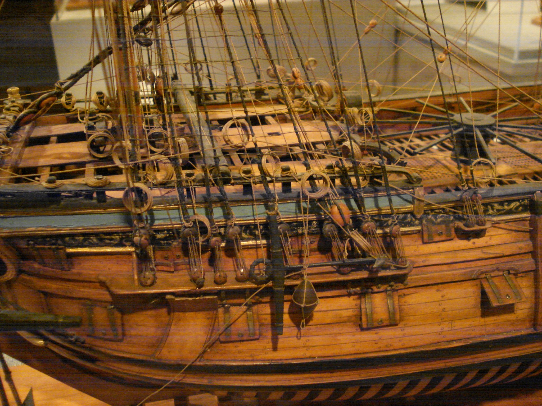
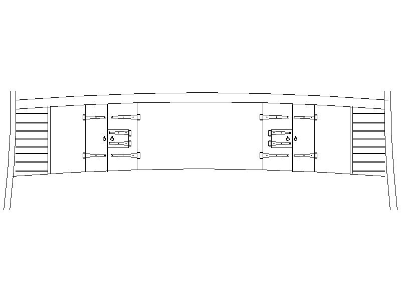
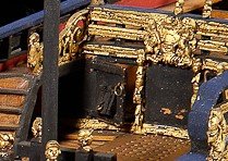
In studying some details on 17th century ships, I found an interesting item I had never noticed before. There were ports in the doors in both the QD and FC bulkheads. I found these described in John Franklin's Navy Board Ship Models on pages 31 and 32. He states "Until the early years of the eighteenth century, ports are often pierced in the doors of the forecastle and quarterdeck bulkheads." From what I can find this is not referring to the beakhead bulkhead in the case of the FC. The below drawing shows the set up of a sixth rate of 1697. The below photo shows ports in the doors as well although slightly different configuration as it is about 1702 and on a royal yacht with the ports opening vertically versus sideways. Similar setups can be seen in other 17th century contemporary models. Question. What are these ports for? To defend the ship against boarders caught in the waist while the crew is taking refuge inside the FC and QD? For passing items through the bulkheads rather than opening the doors? I am anxious to hear any ideas, but especially if based on contemporary information if it exists. I posted this in the Charles Galley build log as well, but thought more folks might see this here.
-
- 3
-

-
Assistance please required re rigging ends
allanyed replied to brightonseagulls's topic in Masting, rigging and sails
Dave, It sounds like you are speaking about coils on belaying pins versus Flemish coils on the deck. If so, this post from here at MSW may be useful for you. -
Edge bending planks
allanyed replied to ortho85's topic in Building, Framing, Planking and plating a ships hull and deck
For a first post Max, this is great!!!!!! Welcome to MSW -
My sincere apologies to you Cri Cri for the hijacking. Allan
-
Every ship that I sailed on had brass fittings and every item that was not in a secure area was painted. The reason was that when stevedores and other service personnel came aboard, be it Europe, Africa, or South America, the brass fire hose nozzles and other brass items that could be removed and carried off would be gone in a heart beat. This was not the navy, but rather, the merchant marine, so we did not have enough personnel to keep an eye on the dozens of people that came aboard for unloading and loading cargo or supplies. The exception was Asia as we would pay off the sifu or bosu and he would keep his crew from stealing these things. Fun times
-
Jaager I agreed with you and still do if the bulkheads being used are those supplied with a kit. I just did not understand that after your explanation why you then changed and said it was moot, that is, open to debate 🤔 In any case, I have drawn and am making the bulkheads for my current build of the 17th century Charles Galley along station lines at times and other than on the station lines to account for gun ports that will be open. The body plan is a great guide, but the individual station lines are not necessarily the lines to be used at times. Totally different than a fully framed model which I prefer, if given the time needed to do so. Allan
-
Deck planking methods
allanyed replied to allanyed's topic in Building, Framing, Planking and plating a ships hull and deck
Thanks to everyone for their kind responses and explanations. Phil, this was just a general question on how others plank and why but your detailed response is greatly appreciated. I usually have followed David Antscherl's description in TFFM of starting with the binding strakes along the outboard edges of the coamings that were already in place and found this to work quite well. I was just wondering about other methods so that the planking stayed symmetrical port and starboard. The first time I used this method was when we were writing the Euryalus books and I have stayed with this method for POF builds but just wondered about alternatives. My current project is POB although that should make no difference in the deck planking methods. -
Jaager Not sure I understand why you feel the regularity and symmetry of the molds is open to debate (moot). As you said, it will be hidden with planking so what does it matter - (except where gun port openings are a consideration as I have encountered in a current POB build.) Cri, I just tuned in to your build and am enjoying the ride. Anxious to see your progress. Allan
-
After 40 or so years of building wooden ship models, this question came to mind this morning. How do you lay your deck planks? This may be a loaded question, but the reason it came up in my mind, I was looking at a build log and the deck houses, coamings and such were fixed in place before the planking was laid. I have done this myself, but never seem to get the planks to end up perfectly even port and starboard. I have tried a few scenarios over the years, and each seems to have advantages and disadvantages. Currently I usually lay in three or four strakes of planking starting at the center line and working outboard. Once the first few strakes are in place I can mark and cut out pieces of the deck at the locations of the hatch and other openings and then fix these coamings, etc. in place before adding the balance of the deck planks. Alternatively I have laid in the binding strakes first which mark the edge of the hatch openings, but it is a touch more demanding in getting these strakes exactly the same distance from the center line and then there is the situation of filling strakes in between so they are all the same width and fit neatly between the binding strakes. Even so I like this method for ships with a lot of hatch openings, but not so much for fishing schooners or other vessels with numerous cabin openings and not so many hatch openings. For large ships, the orlop or platform decking is a different situation as the planks are not continuous across the tops of all the beams so have not been as much of a concern. If anyone has other methods that have been successful for them I would love to hear about them in my never ending quest to learn more. I am not suggesting there is right way or a wrong way, I am just curious as to how others go about this and why. TIA Allan
-
How to connect yards to masts??
allanyed replied to ObviousNewbie's topic in Masting, rigging and sails
I very much like and have used Anderson's book for ships built before the 1719 Establishment but it is not always applicable to later ships such as Diana which was from 1794. Some things remained the same, many things are not. For example there were no preventer stays before 1700 and these were not snaked together until sometime in the 18th century and then, usually only in wartime. Another example has to do with the rigging of the yard to the mast as mentioned previously as the lower yards had parrel ropes before 1760 which Anderson describes in some detail but they would not be appropriate for Diana. It may be that I have a small paperback copy, but Anderson's illustrations are sketches and not very clear. (It could also just be these old eyes 🤪) Allan -
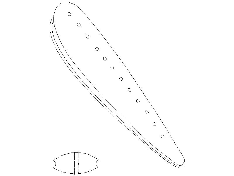
Mike, Making the euphroes is fun little project. Close grained hard wood is important as there is a channel to be cut and a lot of holes to be drilled with even spacing. The description by Blue Ensign based on Lees' Masting and Rigging and the sketch in the post from Twintrow on May 15, 2013 above describes and shows how it is rigged to a stay and a top. If you still are having a difficult getting a grasp on this, what specifically do you need? Below is a drawing based on the euphroe illustrated in Lees Masting and Rigging on page 168. Lees also illustrates the rigging as described in B.E.'s post above on pages 44 and 45. Hope this is a little bit of help to you. Allan
-
Carlings
allanyed replied to Don Case's topic in Building, Framing, Planking and plating a ships hull and deck
Go with Druxey's advice Don. To answer your question on size, the carlings do not have the same scantlings as the beams and they run fore and aft rather than athwartships. They may have different dimensions for each deck in most cases depending on the size of the beams which would vary as well and the number of tiers (rows) of carlings varies as well. For Discovery there were probably two tiers port and two tiers starboard and in the neighborhood of 6 inches broad and 5 inches deep. There were also rows of ledges between the carlings which were probably about 3.5" broad by 3" deep. There is more to this, so again, follow Druxey's advice and read up on these in the books he mentions. I must say it is a pleasure to see you take such an interest in the details!!! Allan -
How to connect yards to masts??
allanyed replied to ObviousNewbie's topic in Masting, rigging and sails
Sorry to be posting this here, but it follows the previous post and is probably applicable to most of the other forums here. Shipman, I agree with you that the issue over all is in fact moot, that is, it is open to debate, not a closed issue. I would be p...d off if someone posted my drawings without permission. I did find the following, at least for the US. Unless you own the copyright to an image or have a license from the owner, posting it online without permission is a violation of copyright. In addition, regarding fair use, there is a limit. The following should be taken into consideration. Without consent, you ordinarily cannot use another person's protected expression in a way that impairs (or even potentially impairs) the market for his or her work. In other words, will posting someone else's work have potential to cause the copyright holder to lose business? Then again, I suspect that snippets that we see posted might actually induce some to buy the book rather than the other way around 😃 There is also the possibility of transcribing a written paragraph or redrawing an image rather than just copying and posting. Just my opinion, but would love to hear from a member that has experience in this arena. Allan -
I agree with Alan and would remove the errant plank or at least the glue and put in a laminate to get to the correct thickness. As to what glue? I have no idea if either CA or PVA will bond the second plank layer to the filler that you used but both are meant to bond wood to the wood, not to a layer of filler. As you move forward, consider that there are those that love CA, especially when in a rush. Others prefer PVA as it is not so quick in curing and the plank can be worked a bit once it has been shaped to fit. If the plank is properly reduced in width as you move forward and widened aft and pre-bent as Chuck Passaro has demonstrated here at MSW so well, or spiled as described by David Antscherl in detail in his write up also here at MSW, it can be held in place with finger pressure for 30 seconds or a minute even if using PVA. Consider that PVA does not have the fumes that will irritate your eyes, nose, throat and lungs which is probably not a good thing considering how many planks you have to glue so may be worth the extra few seconds it takes if you go with PVA. The pluses and minuses of PVA versus CA continues to be discussed here at MSW quite often and there are advocates of both so pick what works best for you. PVA has been around since 1912 and CA has been around since 1942 so they both have something of a proven track record. Allan
-
How to connect yards to masts??
allanyed replied to ObviousNewbie's topic in Masting, rigging and sails
Newb, The short answer - based on Lee's Masting and Rigging, the fore yard and main yard in 1794 would be secured to the mast with a truss pendant and the topsail and top gallant yards would be secured to their appropriate masts with parrel ropes using two rows of trucks (rollers) and ribs. There would also be the jeers on the lower yards and ties on the topsail yards for raising and lowering them. Lees' Masting and Rigging shows detailed drawings on how these are rigged. I am sorry I am not posting these drawings from Lees but there are copyrights involved. There may be images in the public domain on the 'net . Allan -
Sloping deck
allanyed replied to Don Case's topic in Building, Framing, Planking and plating a ships hull and deck
Hi Phil, "Rounding down" is a new term for me. Regarding rounding up, I have never seen this term, but it surely is the same as the terms that I have seen used. For the Brits (I can't speak for other nations), in studying the Establishments of 1719, 1745 and 1750, the Shipbuilders Repository, and several contracts from the 17th, 18th, and 19th centuries I have only seen the term "to round". The words up or down are not used at all. In the case of the Establishments and the SR, the scantlings for how much the beams are to round are given for each rate of ship as well as for each deck. Later, in the early 19th century Steel used "to round" in the main text of The Elements and Practice of Naval Architecture but in the scantlings portfolios, he used the term "to round up" for each deck and each rate. Not trying to be picky here, just finding this very interesting, especially the term rounding down as I cannot find it used anywhere in either contemporary or modern sources. As to the amount of sheer Steel does give the location of the various rails based on the location of the sheer rail which he detailed in relation to the upper edge of the rabbet of the keel "afore, midship, and abaft" in folio fifty-five. Appreciate if you could steer me to where you found the information on sheer and rounding down scantlings. Thank you very much. -
Jim, What do you mean by a freezer? Photos? Thanks
-
That's what I thought, but in the photos they looked round. Thanks for all your hard work Chris Allan
-
Chris, the model is stunning!! Question,,,, the gratings on the forecastle appear to have square holes as normal with the battens and ledges, but those in the waist look like round holes. Is this correct or is it just that the image is not clear and they are square holes? Thanks Allan
-
Interesting questions and now I have to ask, why? I don't think you will get too much first hand experience in 2021 😁 If you had asked about 50 years ago I had an old German bosun for a teacher from the days of sail that taught knot tying amongst other things at Kings Point who would have had the answers for you. He went to sea at the end of the 19th century/beginning of the 20th century at the age of about 12 on sailing vessels and continued to sail for many years before taking up teaching. If you get no hands on experience here from the members, maybe consider finding someone that sailed or sails today on the ships built for various schools or movies in the 20th century such as the Rose which came about in 1970 and was then used in the film Master and Commander. Allan
-
Katt, There are several good books on rigging British ships for which most, if not all, of the lines on Endeavour would be comparable. The ideal book would be Masting and Rigging English Ships of War by Lees as it covers the most detail but can be costly. There are others as well that may be of help, including The Young Sea Officer's Sheet Anchor by Darcy Lever. It is a contemporary work to the early 19th century. David Steel's book on rigging is great but does not really show much, if anything, on what lines go where. Still an interesting piece to have and can usually be found on line for free https://maritime.org/doc/steel/ You may find all of these to be overly complex for your project, but they have much more accurate information than the majority of kit plans. Allan
-
Yes, as Henry pointed out, the line between deadeyes for shrouds or when used for stays before hearts came into use and then later for the hearts are lanyards. Age old question about whether they were tarred or not. In the photo of a contemporary model from Preble Hall you can see that the lanyards for the shroud deadeyes and for the hearts for the stays are lighter in color than the shrouds or stays. I also have photos of a number of contemporary models that show the shrouds to be untarred so the models themselves could be re-rigged or not always representative of the actual rigging at times. Allan

-
Katt, welcome to MSW. Did you contact the manufacturer? It looks like the Artesania Latina kit. If it is, and no one responds here that can give you their plans, https://artesanialatina.net/en/104-ship-models might be a place to start. Once you get going please know that there are a lot of folks here that can help if you have any questions. Allan
-
Dave, Can you indicate with which stays and which halyards you are concerned? "Normally", all the stays would be tarred thus a dark brown (or black as that is what they provided in the kit) and the halyards are running rigging thus would be a tan color as they would not be tarred. The tarring is as mentioned above by Davis to preserve it. Running rigging going through blocks and sheaves would gum these up if tarred. I realize you spent a lot of time with the rigging, but you might want to reconsider and replace the halyards with the proper color rope if you used used black line. As this is your first build I hope you are not being discouraged with the mistakes found in some kits. If nothing else, it makes for a great learning experience before embarking on the next modeling venture. Allan