allanyed
-
Posts
8,149 -
Joined
-
Last visited
Content Type
Profiles
Forums
Gallery
Events
Everything posted by allanyed
-
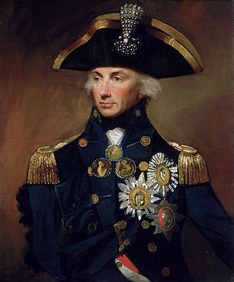
Try this one https://www.myheritage.com/deep-nostalgia and then where it says upload a photo, get any photo from your own file to enter. Or you can save the Nelson image below if you want to try that one first. Or, go to the home page, click on Family Tree then click on Animate Photos. You can then upload a pic and it will do its thing. You may have to enter your email address and a password to get started.
-
Alan, You couldn't hide them so let the builder beware, do it right. 😀 Of course, the average viewer would not know a mistake except maybe for something glaring like a broken line or something similar. The members here are another story and would likely spot errors as long as the name, year, and nationality are known. Jan, do you have the name and era of that model?
-
Mark, If you get into the site, you can just insert any portrait image. I did Nelson, George Washington, and long past relatives. Seeing grandparents that I remember vividly moving and blinking was fantastic, but a bit on the creepy side. I sent the same link to a member here and he had it open right up to Nelson so you may want to give it another try. Free site unless you sign up for the premium package or premium plus which helps in building a family tree. Try this one for Phineas Pett 1570-1647 https://www.myheritage.com/deep-nostalgia/result/1103411981-500004
-
Discovered a new (for me) website that takes any photo and animates it. I tried it with a portrait of Horatio Nelson and got what you can see on the attached. Spooky, but interesting. https://www.myheritage.com/deep-nostalgia/result/1103411981-500002
-

HMS Discovery 1789 by Don Case - 1:48
allanyed replied to Don Case's topic in - Build logs for subjects built 1751 - 1800
Making the cannon and carriages is what I have often gone to while the glue dries. Knees may require a bit of field fitting so should wait. The spacing between deck beams may vary so the horizontal knees will vary in their fore and aft length. The vertical knees will vary with the lay of the inside planking, plus some are canted. For vertical knees at least, it is often a good idea to made card templates to get a perfect fit, then use the template as your guide for cutting out the knee itself. -
Making Knees
allanyed replied to Don Case's topic in Building, Framing, Planking and plating a ships hull and deck
As posted above, depends a lot on the wood. Castello and Buxus are fantastic for this purpose but there are no doubt others. There is no need to make laminated pieces. If you want to truly aggravate yourself consider the following. I was going to make knees from crooks as was done in full scale and collected hundreds of pruned pieces from an apple orchard near our home and debarked them and let them dry. As they were so small they were ready in a few months. They were the best way to go for strength but took so much work that in the end it was just not worth it as this is a model after all and the stresses are not such a big deal. -
Very well said Christian!! Enjoy!!
-
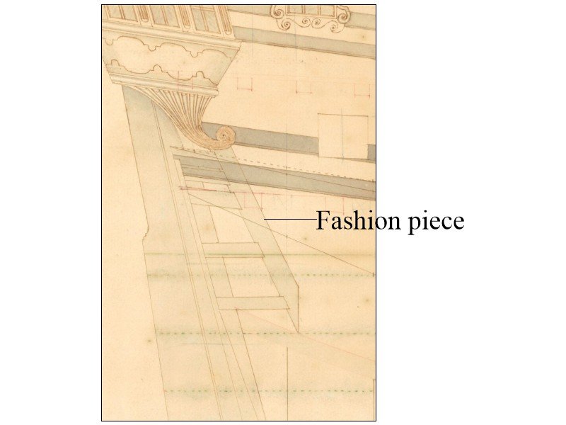
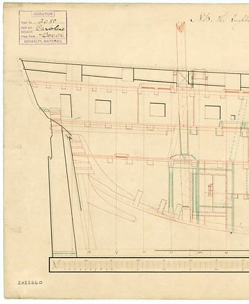
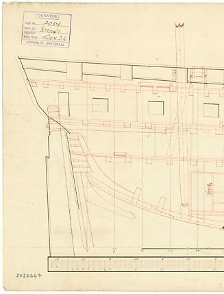
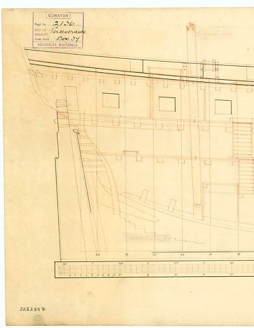
Hi Don, It depends, as seems to be usual. Often the wing transom had a tenon that sits in a mortise on the aft side of the fashion piece rather than on top. Keep in mind that Steel is 1805 and Discovery is 1789 so Steel may not necessarily apply to Discovery. I don't know one way or the other, hopefully some member has contemporary information on this. The first drawing below shows the wing and other transoms with mortise and tenon for each joining on the aft side of the fashion piece. It is a bit difficult to see the wing transom as the wales are dark but the wing transom and fashion piece lines are there. If you have trouble seeing this PM me and I can send this to you so maybe you can see it enlarged with more clarity. It can get even more complicated in some cases as there may have been what might be called a fashion piece and half or aft fashion piece. I hope some member can give the proper terminology for these double fashion pieces if they are actually called something else. The forward one is fayed solid to the aft one so may all be part of what would be called fashion piece(s). This was the case in the second drawing of Aquilon 1786 where the second transom sat on the top of the aft fashion piece, not the wing transom, but perhaps in you case it did sit on top of it. If it did it would probably have had a mortise and tenon into the aft side of the frame (forward fashion piece?) but I don't know that it would have a mortice and tenon into the top of the aft, or shorter fashion piece. The full framing drawing is in the Wiki list and can be found at https://upload.wikimedia.org/wikipedia/commons/a/a3/'Aquilon'_(1786)%2C_(also_spelt_Aquillon_or_Acquillon)_RMG_J7958.png
2.thumb.png.cc7c430105f6b3fbb954968a7d715081.png)
-
Hi Christian, Three mm moulded is about 8.5 inches at your scale which is about double what I am used to seeing. With this dimension plus the thickness of the planking inboard and outboard, the cap rail would be about 14 inches wide or more . Is this correct for your St. Philippe? I like the heaviness of these top timbers from a modeling stand point as they can easily break when at scale (I speak from experience and many curse words have ensued when it happens) but it may not look right. I am not saying it is wrong, but it is just something different than what I have seen for British ships, the top timbers running from about 2.5" (<1mm at 1:72) to 5" (1.76mm at 1:72) moulded dimension in the late 17th century depending on the rate.
-
Brett, may be worth a try, but I agree with Alan, cutting the gap so the planks are all the exact length to fit snuggly into the rabbet of the stem and stern post seems nigh impossible. I just can't see this working, and if it doesn't, all the planking would have to come off and be redone with the tried and true method of planking after the stem and stern posts are in place. Same thing for the keel. The garboard strake should fit snugly into the rabbet of the keel so if you plank and then sand the bottom flat there will be nothing left of the edge of the garboard to fit into the rabbet.
-
Looking good Cri Cri!!! Will there be a wing transom to hold the stern timbers or do you plan to glue them to the bulkhead? I use the wing transom, but the added strength of gluing to the aft most bulkhead as well, like you are showing, seems like a very good idea. What is the moulded dimension of the frames at the bulwarks? The reason I ask is that they seem to be quite thick. I would think they would be in the range of 3 to 4 inches, where the top timbers would be if were framed versus POB. At a scale of 1:72, these look to be about 24 inches moulded so the cap rail would be extremely wide. I am looking forward to your next posts and photos.
-
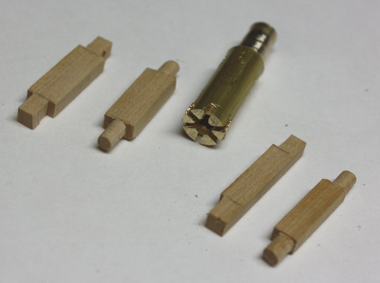
Dave, Your jig is similar, and better, than what I have used in the past. Very nicely done. Your axles appear to be hand carved and not exactly round. You can do this and leave them a little large to start or just leave them square to start. Then, if you have or can get a small piece of brass or steel rod, you can drill a hole in the center the diameter of the axle that you want then file or hand saw slots to create cutting blades. Once done, chuck the cutter in your drill and round out the axles. A small drill press is easiest to use, but a hand drill will work as well. Photo of one that I made from a piece of scrap brass rod in a about 20 minutes is below.
-
HMS Bounty by AdamA - 1:48
allanyed replied to AdamA's topic in - Build logs for subjects built 1751 - 1800
Adam, This is one of the nicest Bounty models I have seen here. One option for the next time you have to bend a transom or anything else that is thicker than a plank or even if edge bending a plank, you might want to consider heating the wet piece once it is fixed in a jig. Chuck Passaro gives a good amount of detail on setting up a jig, and it is a relatively easy thing to do. It leaves room to heat the wet bent wood with a small travel iron. In some cases where the parts are really small, I use a clean flat head tip on my solder gun to heat the wood. Just need to be a bit careful not to scorch the wood. The heat will fix the curve in place and save a lot of wait time compared to air drying which may not hold as well as the heat is a key element in the bending. -
Charlie, Unless you are building at about 1:24 scale or larger, cloth sales will likely be way out of scale, especially noticeable being any attempt at sewing. Many beautiful models have been ruined when rigged with cloth sails due to being out of scale. Two alternatives, rig without sails. If you must have sails consider using silkspan. This has been addressed a lot lately here at MSW. One example is the December 4, 2020 post on making sails with silkspan in the BoothBay 65 build log. For a step by step explanation with a lot of detail on making sails consider purchasing the supplement to Volume IV of The Fully Framed Model by David Antscherl for $7 from SeaWatch Books www.seawatchbooks.com/ItemDisplay.php?sku=115003 You can also check out the video www..youtube.com/watch?v=g_m_VWzk4w8 Between these three sources you will have some alternative styles/methods using silkspan as well as having answers to most, if not all, of any questions that may arise.
-
Deadwood
allanyed replied to Don Case's topic in Building, Framing, Planking and plating a ships hull and deck
Hi Bruce, The spectacle piece is where chain or rope is attached for the emergency steering. The following is a basic sketch. It is typically located just below the lower hance on the aft part of the rudder.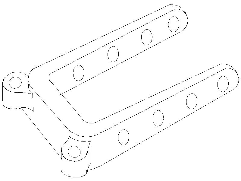
-
Deadwood
allanyed replied to Don Case's topic in Building, Framing, Planking and plating a ships hull and deck
Don The rudder was generally made in several pieces and this point is usually the place where the aft most piece (backing piece) fays to the center piece. I THINK the hance is more or less decorative and is just an extension of the backing piece. There is actually a lot in the making of the individual pieces as well as how the hinges, reinforcing bands, and eyes/spectacle plate for emergency steering. -
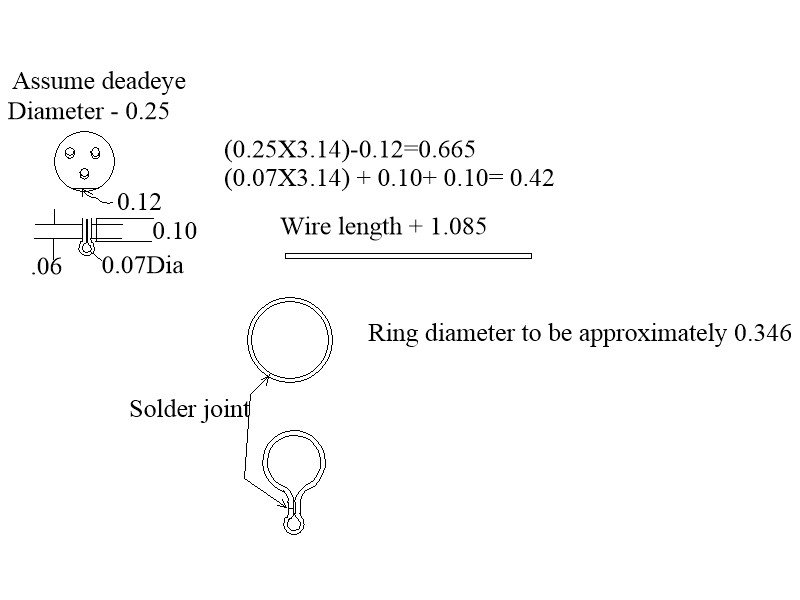
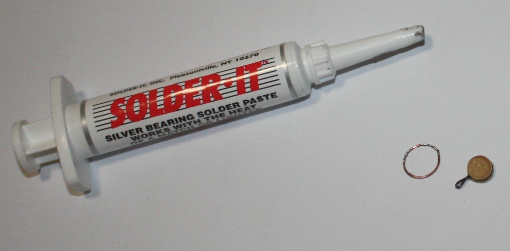
Dave, To further clarify, the sketch and photo below may help in figuring out the sizing for the rings to make the upper link that goes around the deadeye. Silver solder takes a little practice but is an extremely useful skill in this hobby of ours. I prefer paste to solid pieces but you may want to try both. I do prefer using copper and soft solder whenever possible. The solder in the photo is extremely strong and goes on with a standard soldering iron. Thin brass wire and silver solder can be problematic as a propane torch is harder to control on very thin wire and sometimes melts the wire if you are not careful. The ring is made of 24 gage bare, dead soft, copper wire. You can get numerous gages from 30 to 12 in 100 foot spools or larger from under $10 per spool. I made three rings in about 3 minutes I tried to pull apart the third one with pliers and it held without any problems. Another advantage of using copper is that I blackened it after it was formed around the deadeye with liver of sulfur. I turned a 1/4" disc for this demo, thus it does not have the three holes that would normally be there. Hope this helps!
-
Need help from a model maker in California !
allanyed replied to Ekis's topic in Wood ship model kits
I second what Druxey posted. I have had the good fortune to have models shipped from the US to Europe on several occasions and to various parts of the US with only two minor bumps that had to be fixed and were easily done by the buyer or a friend of the buyer. Antiques and art shippers are definitely the way to go. They are professionals at this and take full responsibility. They carry insurance based on the value that you give them for the model just in case, and photograph everything as the process goes along. UPS, FedEx, DHL et al are not always very good handlers of delicate items and should be avoided completely for this kind of shipment. It is not a cheap proposition, but worth it in the end. -
Dave, I have not heard of this problem before, it may the rings (upper link) themselves that are not quite right. The Caldercraft upper links in the picture posted are not solid rings as they should be so if this is the same situation that you have Dave, this may be the problem. It is easy to silver solder brass (or even soft solder a copper wire) into a large ring. The heat in silver soldering the brass will soften it enough to easily form around the deadeye. This is then squeezed into the groove of the deadeye with the excess forming a smaller ring for the middle link of the chain. There will be a flat spot between the large ring on the deadeye and the small ring that will sit in the slot in the channel. The first one you make is the hardest as you have to figure out the size of the initial solid round ring before squeezing it to shape so the deadeye sits on the channel and the small ring is just below the bottom side of the channel. I have no idea on how to figure the math so have just gone with a piece of copper wire to get the approximate size then solder and test fit. If too small, the next will be a hair larger, if too large, a hair smaller. Once I have it right, I cut it apart and straighten it then cut as many pieces as I need with all of them the proper length to make the proper size upper link. David Antscherl goes into some detail on page 262 of Volume II of TFFM and recommends using brass and a high melt point silver solder. He also points out the need to have the straight portion between the upper and lower loops long enough to allow the unit with a deadeye to be pulled up about a scale inch or so above the channel when tensioning. Glue of any kind, be it CA or Gorilla or epoxy, is probably not a good solution.
-
Deadwood
allanyed replied to Don Case's topic in Building, Framing, Planking and plating a ships hull and deck
Don, Not sure what notch to which you are referring. Can you mark the notch on one of these or some other picture showing the notch? There are normally two square holes through the rudder. I have always assumed one is for the tiller that is set up with the ship's wheel and the other for a hand controlled tiller in the event the first is shot away or otherwise out of commission. I may be off base on the reasoning for two, so would welcome contemporary information if anyone has it. Allan -
Deadwood
allanyed replied to Don Case's topic in Building, Framing, Planking and plating a ships hull and deck
JIm has an excellent point as to selecting pieces of timber. Regarding the deadwood aft, I looked through about 50 inboard profile drawings in the NMM collection over half that I looked at show no individual pieces. The rest all show the same curved piece as seen in four examples below but no others which leads me to believe there indeed was not set pattern. Goodwin goes into some detail on pages 12 and 13 of The Construction and Fitting book. The deadwood was shaped to generate the correct underwater shaped of the hull and the height depend on where a relatively sharp full hull form was required. The fore deadwood was not always present and was mainly where a sharper entry was needed and fitted directly over the boxing joint. He goes on to say that the aft deadwood was made up of about eight pieces. He gives a description of the shapes of the lower pieces and upper pieces as well. He also states that the number off individual pieces varied depending on the builder for this area was a good opportunity to utilize large offcuts of timber to minimize wastage.
-
Thank you Tom! Bill, Is the material in the photo the Magi Gift string? I do not mean to be negative at all, but it does not look like rope but more like string or thread. I know that with Syren no longer making rope, buying realistic rope is difficult, but I believe there are still some suppliers out there that offer rope versus thread like material and hopefully some members can offer some sources. I am not looking forward to the next time I have a project that requires rigging as it will be my first go at making my own rope and I have trepidations galore.
-
Bill, Can you do a close up photo of the rope. It looks more like thread or string than rope from the pics. If that is the case, you may want to consider another source or taking the plunge to making your own. As to black versus brown, you can explain to viewers that there really never was any black rope. From what I have been able to find, the Stockholm tar is actually a distilled product. Arch, where do you get your Stockholm tar? Thanks
-
Bill If it is not a big problem I would forget the black. The standing rigging was darker due to being "tarred" but this gave it a dark brown color, not black as it was not a tar like we see today on our streets, but rather pine tar. Your Coke brown looks pretty good. For the running rigging something close to a color like Pantone 14-0721 TCX would be a good choice, but most any tan should be OK for the running rigging.
-
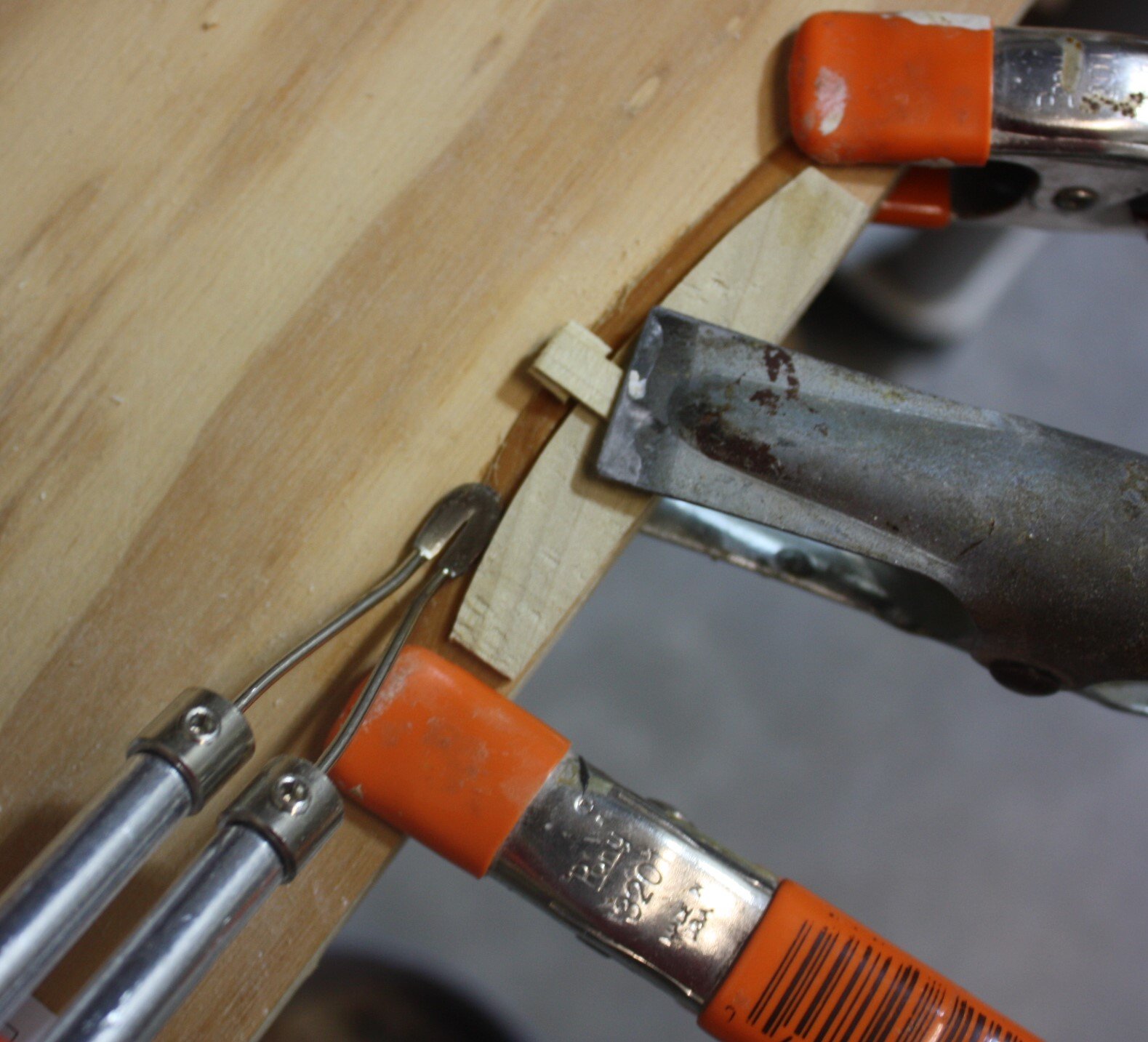
Bending with steam easily
allanyed replied to a topic in Building, Framing, Planking and plating a ships hull and deck
The mini travel iron idea is a good one that Chuck Passaro demonstrates in detail in his tutorial. For very small pieces I now use a flat blade on a soldering iron. Care needs to be taken not to burn the wood so I turn it on with the trigger for a few seconds, then turn it off while "ironing" for a few seconds, then turn it back on for a few seconds, and so forth. Works really well once I got the hang of the timing so as to not burn the wood. The first photo shows a pieces that has been soaked in water and the beginning of the ironing. In the second photo you can see the lighter color of the same piece after heating and the water is evaporated. The wood in this case is castello box, so hard woods can be done with this method. Softer woods may not need to be soaked first, but this wood did split if bending when dry before the heat procedure. For larger pieces I do prefer an small steam iron.
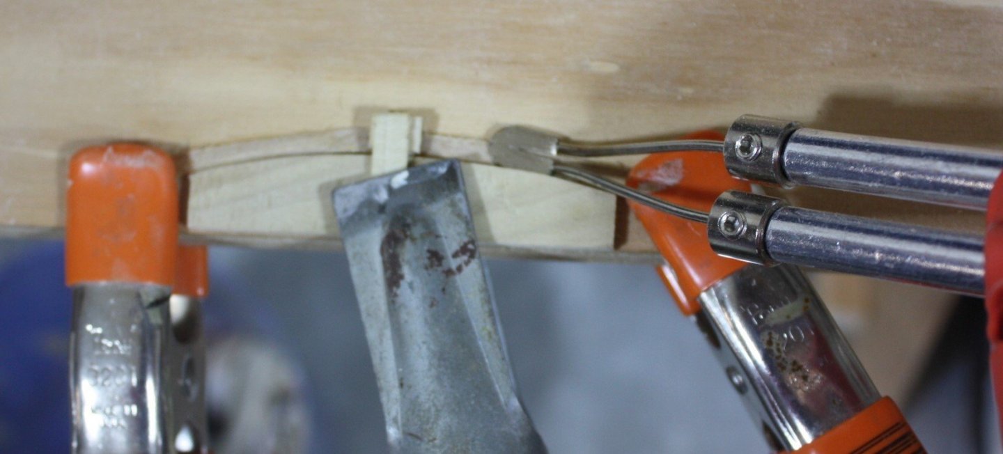


2.png.4eed4090a67babcb9c2bedd860895afa.png)