allanyed
-
Posts
8,149 -
Joined
-
Last visited
Content Type
Profiles
Forums
Gallery
Events
Everything posted by allanyed
-

Dead flat stations
allanyed replied to Don Case's topic in Building, Framing, Planking and plating a ships hull and deck
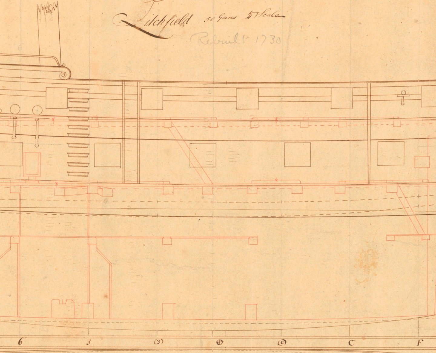
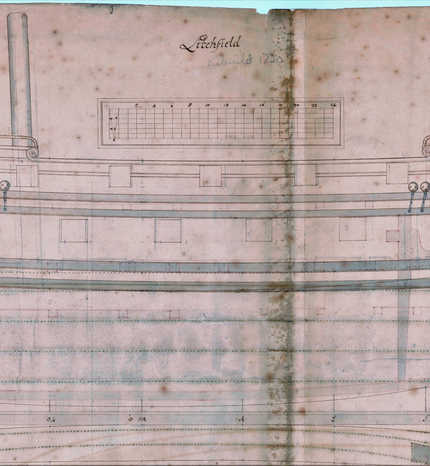
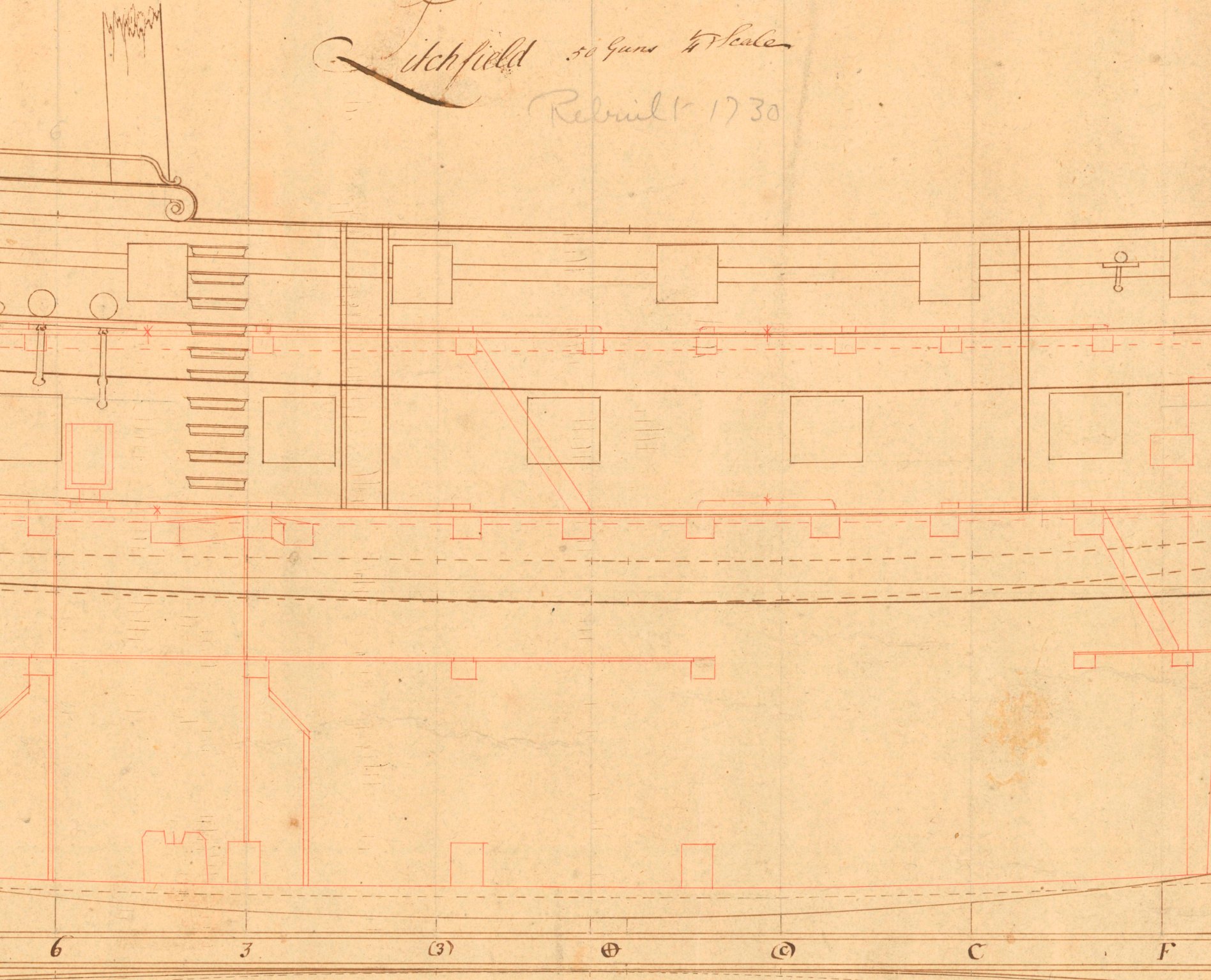
Some drawings show stations near the dead flat in brackets, some don't. Some show letters forward and numbers aft, other show just numbers. In place of brackets, some show the letter O in front of the station number or letter. (Attached example of Litchfield 1695- Note that the first example is the 1695 version, NOT the rebuild of 1730 which was a completely different ship.-- - second drawing) Depends a lot on the era, but not always. Whatever the case may be, the body plan station identifications match with those on the profile drawing. Allan
-
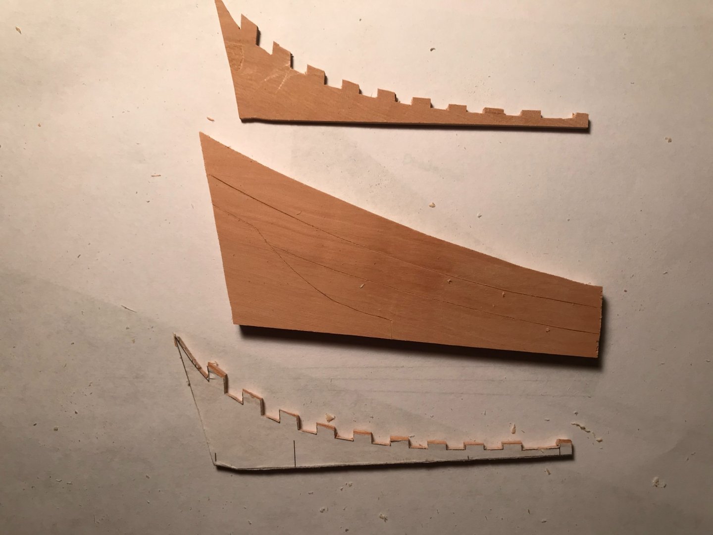
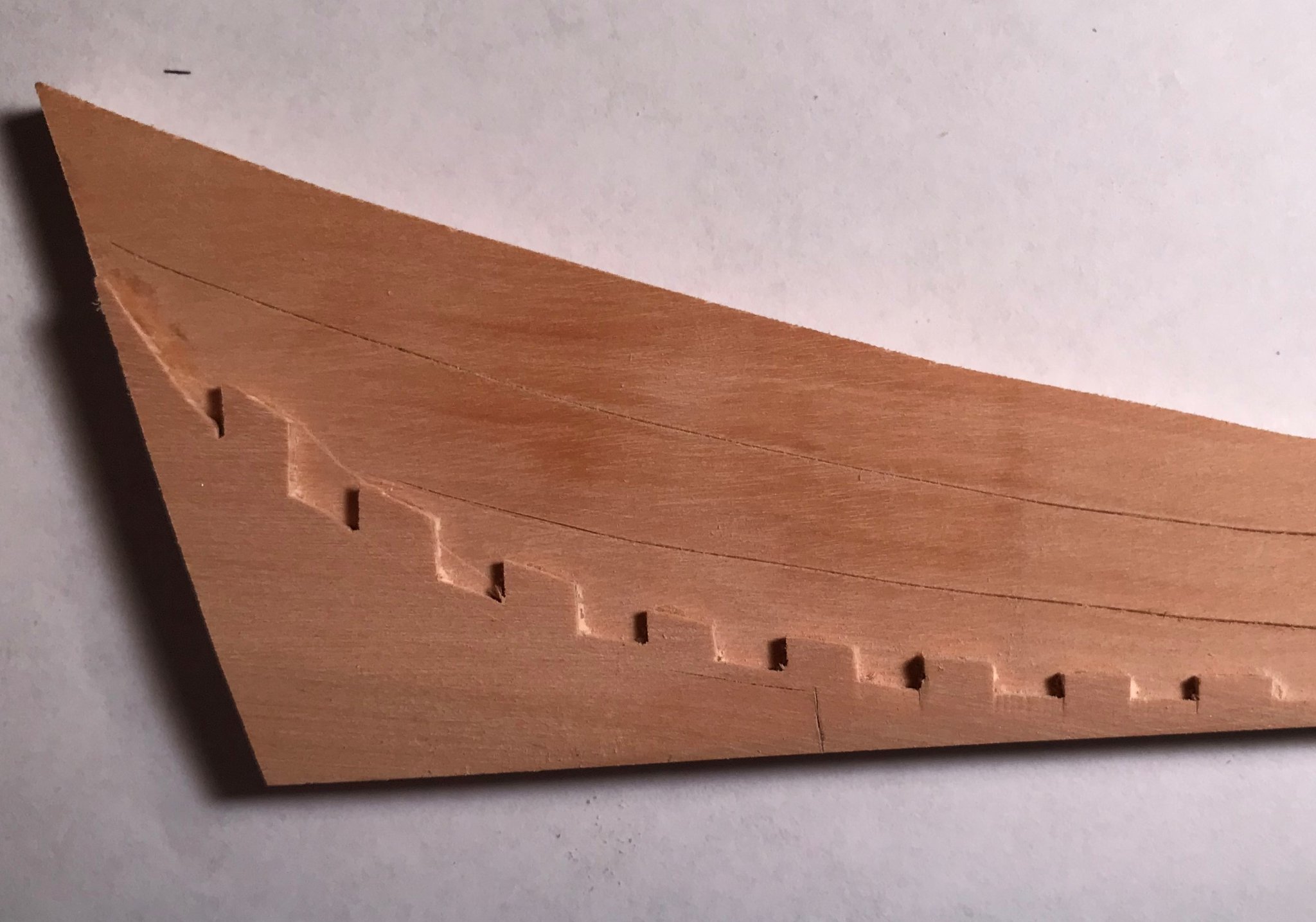
The rabbet is at the top of the keel only and is basically the same depth it's entire length. The bottoms of the frames at the deadwood are above the rabbet and rest in steps or in some cases along a curved bearding line that is cut into the deadwood. There is tapering vertically and horizontally along the length and height of the deadwood. Look at the various scratch build logs here at MSW and you will find how this is done. Not sure if your project has steps or a curved bearding line, but the tapering is present for either style. It can be done with a mill, chisels or assembled as a sandwich of three laminations. The photos below show individual laminations for a 50 gun ship of the late 17th century and the assembled laminations in the second photo. It is pretty easy to cut and then taper the outer laminations and glue to the center lamination. The bottom of the assembled deadwood will rest on the keel where the rabbet is. I know the jog was pretty much standard, but I don't recall the reason for it being there. Allan

- 1 reply
-
- 1
-

-
Dead flat stations
allanyed replied to Don Case's topic in Building, Framing, Planking and plating a ships hull and deck
Don, Look at the profile plan as well. There is only one dead flat. On contemporary plans the "station" marked with a + or X within a circle is the dead flat. On the profile It is sometimes shown as a single line or sometimes with two lines within which a floor timber could fit. For the Dorsetshire 1757 example below, there are two lines. In this case the lines are 14 inches apart._InboardProfileandBodyPlanRMG_J311275cropped2.thumb.png.880d82a09f45052c16b73fad9271a145.png)
-
1/48 HMS Surprise, who makes the best flags.
allanyed replied to ratskiss's topic in Wood ship model kits
Keep in mind, that whatever material you use and you are looking for realism, the flags are not normally flying, especially if there are no sails or the sails are furled, but rather are draped as Jim has shown in the photo in his post. I never really thought about printing my own flags until reading the posts above. I just tried a sample on silkspan and it worked!!! I taped the silkspan onto a plain white page before printing. Once done, Silkspan is easy to drape if wetted with some matte medium. BUT, keep in mind water proof versus non-waterproof inks. Laser printers are the way to go for this feature. If an ink jet printer is the only choice, matte medium is not a good follow up for draping, but rather some other medium that will wet the silkspan and not cause the ink to run. My little test print on silkspan follows- about 2.5X3.5" I would be interested to see if anyone has more info on draping a flag without ink running . Allan
-
Some good ideas for those that prefer Xacto knives are given above. I do like to use the Xacto handles for keyhole and other small saw blades, otherwise, when it comes to cutting blades such as the all around Number 11, Swann Morton is far superior in a sharp cutting edge as has been reported here at MSW numerous times. Allan
-
Good find Sticker I am OK with my Swann Morton scalpel handles as they are flat which is one of the reasons I went to these and gave up on Xacto, the handles for which are round and therefore can roll. This can be a bit treacherous should it roll off the work bench as it seems to always falls blade first and usually right at a thigh, knee or foot. Using this Polymorph on the Xacto handles to make it out of round or some such that it will not roll could be a useful safety thing. Allan
-
Don, To confuse things even more, the curve of the deck beams in the scantlings of The Elements of Naval Architecture (Steel), the Shipbuilder's Repository, individual contracts, and the Establishments is called rounding, round up or is said "to round " rather than camber which I believe are pretty much the same thing. I have not seen any of these contemporary sources use the word camber , so if you are looking for the value look for round or rounding. These sources give the rounding for each deck which varied from deck to deck as well as rate to rate. Allan
-
For blackening copper, liver of sulfur works very well and can be applied to parts that are already attached to the model without staining the wood. See Ed Tosti's Young America clipper build log as he goes into some good detail on doing this. I have not found it to work on brass though. Allan
-
It should return to the same dimension. I would still consider "borrowing" the iron in the laundry room and using heat. Takes a few minutes versus waiting hours or more for a soaked piece of wood to dry completely. Chuck Passaro's planking tutorial will give you a lot of great information. One other way to find out is do a test piece and see if the the plank does wind up at 4.5mm. Allan
-
HMS Endeavour's Longboat Rigging
allanyed replied to Dougal Mack's topic in Masting, rigging and sails
Dougal, If no one posts the information for you maybe try a search on the RMG Collections site for longboats and you may find what you need. There are scantlings and drawings in W.E. May's book Boats of Men of War as well. Not a lot, but at least some information including a photo of a contemporary model from RMG of HMS Medway's 28 foot long boat which is cutter rigged with spike type bowsprit, mast, boom and gaff. Allan -
Question regarding the base of the mast
allanyed replied to DaveBaxt's topic in Masting, rigging and sails
Dave If the mast is the correct diameter where it pierces the deck, file the ring. If the mast is larger in diameter than it should be, sand the mast. I have no idea what the mast diameter is supposed to be, but lacking information for colliers launched in 1784, you might be close using the formulas in Lees' Masting and Rigging for Royal Navy vessels launched between 1773 and 1794 on page 183. Allan -
My head hurts after reading the last question 😁 1. When the wood is wet it indeed does expand. When you bend and heat it (heat is what makes the bend hold well, not water) it will be the same width. BUT, the planks are not the same width from one end to the other. They would be tapered from the dead flat forward and widened from the dead flat aft, so there is more to be concerned with. 2. The strake is heated and thus dry before putting it on the hull so I would think that no flat spot should be there. 3. Your concern makes sense and I am not sure because as mentioned in number 1 above, the strake needs to vary in width along its entire length other than in the dead flat so if the beveling has an effect, it should not be a concern as each strake needs to be shaped therefore it can be adjusted. Even so, the amount and direction of the bevel is dynamic along the entire length much like the shape of the rabbet is dynamic along its entire length. Allan
-
Question regarding the base of the mast
allanyed replied to DaveBaxt's topic in Masting, rigging and sails
If you are going to use wood, you might want to consider something close grained in place of the type of walnut found in kits which will likely fall apart before you are finished. American black walnut is an exception in my experience. Even a softer species such as basswood or poplar will work, but any close grained hard wood is probably a better choice. You can start with a small block that is perhaps three or four times larger than the OD of the ring. Clamp it in a vice and drill a hole to match the diameter of the mast at the deck. Then take off a slice that would be the right thickness of the ring above the deck. Then you can cut a circle with a scroll saw close to the OD or take of individual sections with a hand saw and then round it with sanding sticks. Another thing you can do is sand and taper a small piece of dowel rod that will fit snugly into the ring you just rough cut once it is close to the final OD. Chuck the dowel in a drill and sand the OD while it is spinning. Once it is to size you can remove it from the dowel and cut the slits and voila, it is done. If you are going to have it represent the canvas cover, you can forgo the slits and paint it gray. Allan -
Question regarding the base of the mast
allanyed replied to DaveBaxt's topic in Masting, rigging and sails
Dave, The above recommendations are good ones. If you want to leave off the canvas to show the wedges you can make a wooden ring and then with a very thin coping saw or jeweler's saw blade cut slits to represent individual wedges. There are some excellent photos of this method on one of the current build logs, I just cannot remember which one. A search of wedges should get you there or a member here may recall where this is. There was no metal ring and as said above is just a cheap and easy way out for the kit builder, ornate or not. The rings really have no bearing on what the cannons look like. If you are shooting for historical accuracy the advice above should be something to seriously consider. Allan -
Joints
allanyed replied to Don Case's topic in Building, Framing, Planking and plating a ships hull and deck
To name a few others, The Fully Framed Model, Volume I, Naiad, Volume I, and Euryalus Volume I all show the boxing joint. Pages 39-42 in Naiad go into a lot of detail on how make this joint with hand tools. Even on a model, especially if a POF, if there is a keel and a lower stem piece, the boxing joint really is something you need to make. If you make some other joint, it is liable to be a weak spot and twist and turn and maybe even break when adding the frames, hawse pieces and subsequently the planking. Plus, this joint is exposed and will be noticeable on the finished model. Allan -
Rick, In the 1780s British ships gun tackle went to 3 inch diameter for guns above 24 pounds and 2" for 9 pounders and below. (Lavery, Arming and Fitting, page 141) NB - 3" diameter rope for running tackle seems awfully large. I am pretty sure this could be a typo and was meant to be circumference. He does not mention 12 pounders or 18 pounders but presumably they would be about 2.5". Lees states that the lengths for common blocks were about 4 times the size of the rope and his rope sizes are always given in circumference. I don't know of any sources for high quality blocks over 1/4" as you asked so making them yourself may be your best option. As you will only need a few, making them out of wood with brass or other material for the sheaves should not be too difficult. Allan
-
Joints
allanyed replied to Don Case's topic in Building, Framing, Planking and plating a ships hull and deck
Don, What Dan shows in his photos is the correct way for English ships. The forward joint is a simplified version of a boxing joint meant to tie the keel to the lower stem which takes stress in all directions at that point, thus the design. What is not shown is that this joint in full size ships is tabled as well and the vertical surface was actually angled slightly, similar to the keel scarphs. The tabling will be hidden when assembled and for our scales of models, they are not adding anything unless the builder would like to give it a go for their own satisfaction. Allan -
Drag I am enjoying following your build thank you for sharing. Regarding the straps, I agree with you regarding epoxy, but as you have already painted the hull you will be gluing to the paint regardless of the type of glue that you choose to use, rather than gluing to the wood unless you scrape off the paint. I would try the epoxy, but also drill the straps before installing to take bolts. Small brass nails work well as bolts and are pretty close to scale at 1:48 or even 1:64 and add a touch of realism. I have found brass nails with the shank at about 0.018" diameter and the head about 0.03 so they look pretty good because they are not overly large. I recall seeing that some folks use brass or copper wire to make small bolts and peen them over to form a head but I find this extremely difficult at our scales without marring the surrounding wood. Allan
-
This is somewhat of a repeat as the various points have come up in various posts in a few forums, but I recently saw photos of sails for a schooner model that were beautifully sewn on the edges and along the panel seams. If this had been a scale of 1:12 or larger they would be close to scale, but as the scale was 1:48 they were grossly out of scale and, for me at least, ruined what was an otherwise very nice model. I know this comes up quite often but there is a solution to get sails that are close to scale and I hope it is worth repeating for those that may want to try something that may add to their repertoire. The smallest common sewing machine thread that I could find and measure was a little under 0.01" in diameter. I wrapped 125 turns on a steel rule in a 1 inch spacing to get the diameter. At a scale of 1:48 this would be about over 3/8" inch diameter thread. At 1:64 it would be over 1/2 inch diameter and at 1:96 it would be over 3/4 inch in diameter, all of which are rope sizes rather sewing material. The tightest spacing on a modern home sewing machine yields about 25 stitches per inch which is having each stitch 2 inches long at 1:48 and 4 inches long at 1:96, again also too large to be realistic in regards to scale. The seams on the panels are typically 2" wide and 4" around the periphery of the sail, that is 0.04" and 0.8" at 1:48 and 0.02" and 0.04" at 1:96 scale. The thickness of duck canvas varied with the types of sails, but 15 ounce canvas was one of the common sizes. This is about 0.06" thick so scale sail material should be about 0.00125" thick if at 1:48 and 0.0006 if at 1"96. Even the finest cloth that I have found so far, with a sufficiently high thread count to look like the threads spacing are close to scale, is 0.008" thick, thus far out of scale as well. In contrast, some folks, myself included, have been working with silkspan, a nonwoven paper for making sails. With two coats of acrylic that I used to get the right color and strengthen the material, it is 0.002" thick, much closer to scale compared to 0.008" for 1:48. The sails can be set up full or furled. Adding reef points and tying off to mast hoops and spars or booms is not a problem. I add a small dot of tubed acrylic that I mix to match the color of the thread where the line goes through the sail and it is very strong when a hole is punched or drilled through these small dots. 2 inch seams for the panels were made with an acrylic paint marker pen slightly darker than the color of the sail itself. The tip of the marker was shaved with a scalpel to a little under the 0.004" for 1:48 scale that I needed as it does expand a bit when charged with paint. Silkspan is not as strong as cloth, but with one or two coats of diluted tubed acrylic paint, it is surprisingly strong. Hope this gives some members a few ideas on making sails that are closer to scale. Allan
- 17 replies
-
- 10
-
-

-
Topsail schooner sail plans and rigging
allanyed replied to Dr PR's topic in Masting, rigging and sails
Phil, As to thermodynamics and priorities I sailed on many ships with steam turbines and up and downers and I drank Scotch. I still drink Scotch but I don't know of any ships using steam these days. Dart, I love the photos of the Mary G. Powers that you posted. I have no idea why the boom is arced but maybe if the rigging is removed it would be straighter. I for one would like to know more on this one. Allan -
Usually the sticks are made of birch so maybe some member has tried using this species and can give you the benefit of their experience. Allan
-
Welcome Desal Your model looks quite nice!! Hope to see more of your work in the months ahead. Allan
-
Topsail schooner sail plans and rigging
allanyed replied to Dr PR's topic in Masting, rigging and sails
George, Regarding the hound and cheeks, the configuration depends on the year and probably the nationality. For British war ships the cheeks extend to the top of the lower mast and the hounds and bibs to the underside of the trestle tree. There are excellent drawings of this area for 1640/60, 1660 up to 1773, 1773 to 1800, and for after 1800 on pages 3 and 4 in Lees' Masting and Rigging English Ships of War. The drawings on these pages also show the rubbing paunch, front fish, mast head battens iron rings and wooldings. Another thing in these drawings is that they show the mast itself is not round in the upper portion, both below and above the trestle trees. Allan -
All the adjectives have long since been exhausted, so all I can say is that your posts are like Christmas is coming ever week or two rather than once a year!!! Allan
-
Druxey, don't know about those in the 18th or 19th century, but could name a few from around the world in the 1960's that I heard about from friends. 🤪

_InboardProfileandBodyPlanRMG_J311275cropped2.png.5a02a9be932908b0ae0889ffb1c09ea3.png)