


allanyed
-
Posts
8,149 -
Joined
-
Last visited
Content Type
Profiles
Forums
Gallery
Events
Everything posted by allanyed
-
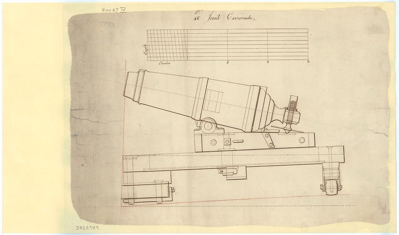
 She looks fantastic and those carronade barrels look great! The mounting for the carronades look really good as well, very similar to the drawing ZAZ6989 at RMG. Looking at that drawing as well as the design in the model, I still cannot determine how the unit was supposed to pivot. Was there a pivot pin or some such? It would not be seen on the model so inconsequential, but I was curious how this was done. I cannot make sense of the construction of the muzzle end of the mounting with only the side view. Hopefully there is a top view to be found. Allan
- 587 replies
-
- 2
-

-
- Indefatigable
- Vanguard Models
- (and 1 more)
-
Reference carriage trucks for an Armstrong pattern 12 pounder of about 1730. Basically I am looking for information that specifies the number of pieces making up each truck at full scale. I have seen many drawings and all of those that I can recall have trucks made of a single piece. If it changed over time it would be interesting to see what changes happened from the time of the Pitt pattern up to and including the Blomefield pattern. There are builds here at MSW that show multiple pieces including one that has 6 pieces bolted together to make up each truck. At our smallest scales it's probably inconsequential, but at large scales this would be clearly visible and I am trying to see how it was done in actual practice back in the day. TIA Allan
-
Totally understood. We moved my mom from Greentree in Boynton to Pompano and my sis is in FLL. Chuck has the right idea, down the shore in NJ is a great way to go. Plus he may not have the need for an AC unit in his shop in the summer time😁 like we do here. Allan
-
Hi Scrubby Chuck will have a very nice small town atmosphere off season, even if it can be a bit crowded in the summer months. Still, an absolutely beautiful part of the country. Most things are comparative. From someone who has been living in southwest Florida for 8 years, I would respectfully argue your point. But this is coming from someone that lived in NJ and worked in both NJ and Manhattan where it is a bit crowded. 😀 Bend Oregon, 100K people. Ave Maria, FL 33K people. Not what I would call a zoo.😀 Allan
-
Hi Chuck Is this down the shore at LBI? As happy as we are to have moved to SW Florida, we miss the Jersey shore. Allan
-
WELCOME TO MSW PIERRE!!!
-
The entire response is well said Hamilton. The rest of life takes a lot of work to succeed, a hobby has no such obligations yet can still provide pleasure. Allan
-
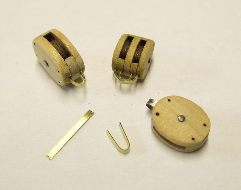
I agree, they are on backwards. Also, the Bluenose had internally stropped blocks. These are available from Syren if you don't want to make your own. Allan
-
Mast Spar and Rigging Spanish Galleons
allanyed replied to Bill Jackson's topic in Masting, rigging and sails
Have you contacted the Naval Museum in Madrid? Email: museonavalmadrid@fn.mde.es -
Exceptionally neat work on the model and I really like the keel clamp as it can be tightened even when there is a taper of the keel at the bow and stern as was often the case. Allan
-
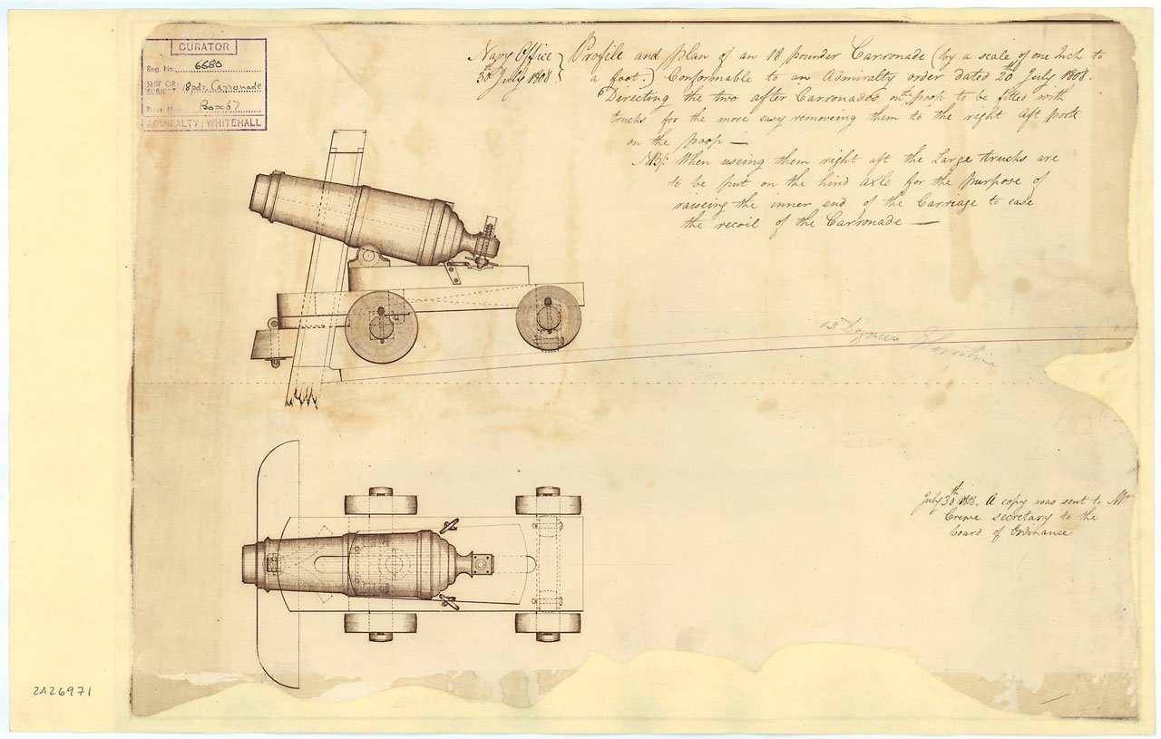
Hi Mike, If you have not already seen them, there are about a dozen contemporary carronade drawings on the RMG Collections website including the two 18 pounders below. In addition I would be happy to PM what I have redrawn from Caruana in whatever scale you would like. Sorry to go off subject, Western PA is our old stomping grounds. We will be in Oakmont in October visiting friends and going to the Steeler/Jaguars game. Black and gold all the way in our family. I did my graduate work at Pitt and the Admiral is a graduate of IUP to boot. I still have many fond memories including the great walleye fishing in Pymatuning. You are in a wonderful part of the country. Allan
- 11 replies
-
- 2
-
-
- Pallas
- 12-pdr gun
- (and 1 more)
-
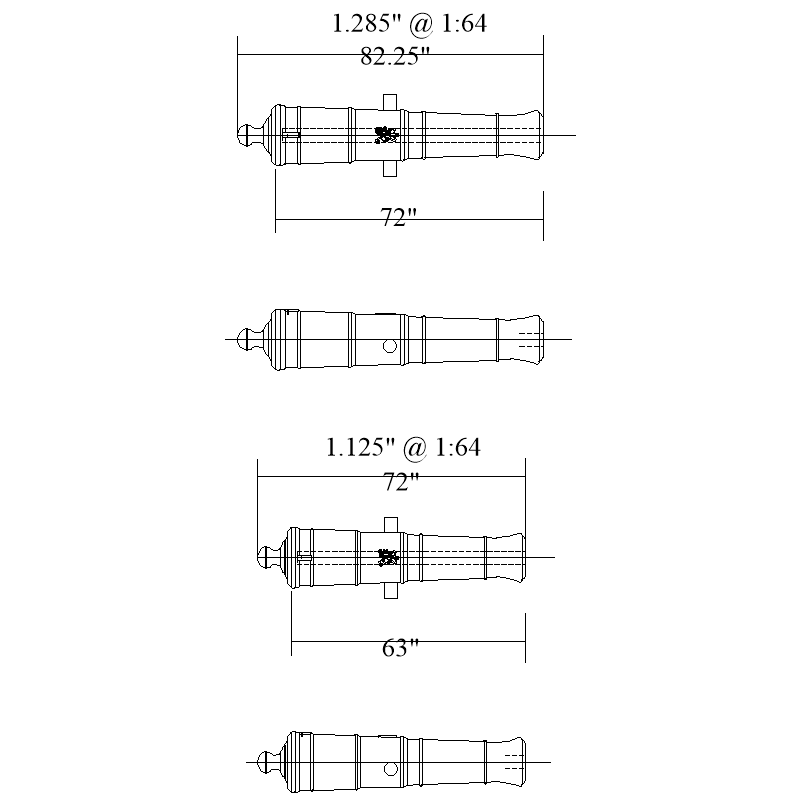
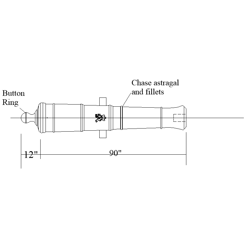
Knocklouder In TFFM Volume II, David Antscherl mentions the lack of room and thus the possibility that they were six feet from muzzle to cascabel rather than muzzle to breech ring. FWIW below is a drawing with dimensions for 1:64 of Armstrong Fredericks which would be right for Pegasus 1776. It shows one with 6 feet from muzzle to breech ring and one with 6 feet from muzzle to cascabel. Note that the AF pattern has a flash pan, cascabel ring and a chase astragal ring. The cascabel ring is a predominant feature on both the Armstrong pattern and Armstrong-Frederick pattern cannons. Sorry for the imperial figures versus metric. The bore in the drawing below is 3.6" as the 6 pounders were 3.5" in diameter. Allan
-
Hi MIke, Totally understood! Enjoy the outdoors, sounds like you are north and contend with cooler winter weather so enjoy the rest of your summertime. Regarding the cannon, again, your project really looks great. For the future keep in mind that the specified length of the gun is the length from the muzzle to the breech ring, not the overall length, thus the dimensions I show in the sketch for 7' 6" barrels. Allan
- 11 replies
-
- 1
-
-
- Pallas
- 12-pdr gun
- (and 1 more)
-
This is absolutely gorgeous and looks like it was a fun break from your Flying Fish model. The carriage and accoutrements are especially great looking. Cannon patterns came up in another topic lately. Assuming this is Pallas 1757, she would probably have had Armstrong pattern cannon. Did all the Armstrong pattern castings have a chase astragal and fillets between the muzzle astragal and the second reinforce ring and a button ring or were some cast without these? Like you I have been thinking about doing a similar project for a change of pace and was curious about this before taking the plunge for this approximate time period. I realize the Armstrong Frederick pattern came into use about 1760, but other than the addition of the primer pan, their appearance is very similar on drawings that I have seen that are based on contemporary information. The sketch below is based on Armstrong pattern drawings in The History of English Sea Ordnance Volume II by Adriana Caruana. Thanks Allan
- 11 replies
-
- 3
-
-
- Pallas
- 12-pdr gun
- (and 1 more)
-
Hello from Switzerland! Mystery model identification
allanyed replied to Nix's topic in New member Introductions
If you do a search here at MSW you will see a lot of these old decorator models which have virtually no monetary value. They are interesting as they are approaching 100 years old and if you like it, that is the most important thing. It is not an accurate model of any real ship but the value is whatever owning it means to you, so enjoy it. Allan -
Danny Vadas' masting and rigging spread sheet
allanyed replied to allanyed's topic in Masting, rigging and sails
Mark, The formulae are really not too complex, BUT, there would need to be double the amount of entries available for ships built between 1670 and 1710. Group 1 Ships with a beam more than 27 feet (Length of the keel for computation X + Breadth Y+ Depth in the hold Z)/1.66 - (Y-27) Group 2 Ships with a beam less than 27 feet (Length of the keel for computation X + Breadth Y+ Depth in the hold Z)/1.66 + (27-Y)) -
1:12 scale landing craft [plans]
allanyed replied to tom q vaxy's topic in RC Kits & Scratch building
You can do a quick bit of research by Googling Higgins boats and go to images for lots of plans then download and save whichever ones you want. Not sure which ones you want though, the LCVP or some others as they built a number of vessels at their yards with the 20,000 workers employed there during WWII Insert into your CAD program and scale to whatever you need or save on a flash drive and take it to a local print shop. DOUBLE CHECK the measurements when they print as half the time I have found them to be slightly out of scale. An engineering printing company is your best best as they seem to always get it right. The pic at the following address can be opened in high res if you click on the original file bottom left of the drawing. https://upload.wikimedia.org/wikipedia/commons/5/51/LCVP_Landing_Craft-_Inboard_Profile_and_Construction_Plan_-_NARA_-_78116787.jpg Allan -
Julian Stockwin's series about Thomas Kidd, 26 books to 2023, I enjoyed these as much as the Dewey Lambdin series. Both are up there with O'Brien IMHO Thomas Paine Kydd, a young wig-maker from Guildford, is seized by a press gang in book one and climbs the ladder from there. Allan
-
Danny Vadas' masting and rigging spread sheet
allanyed replied to allanyed's topic in Masting, rigging and sails
Mark, Thank you! IF I can come up with the formula can I send it to you to fix the program in the data base? I don't need to do this just for me as I have a copy of Lees which I have used in the past for that span of years. Allan -
Danny Vadas' masting and rigging spread sheet
allanyed replied to allanyed's topic in Masting, rigging and sails
I think I will stick with Lees' and do it the long way with his set of ratios. Would love to have the original spread sheets that Danny made and fix the early dates although the math is not so easy for that 1670-1710 period. Allan -
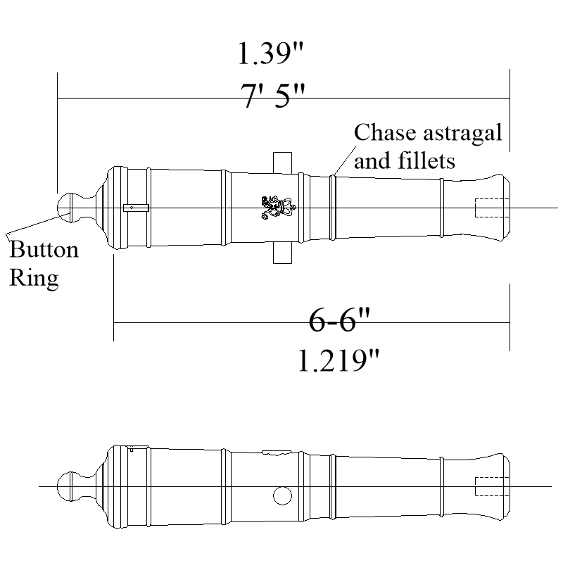
Thank you. I am guessing these would have been Armstrong Fredericks which came into use about 1760 and which are different than the pattern in the picture. It appears to be missing the ring around the button and the chase astragal and fillets found on both Armstrong and Armstrong Frederick patterns but probably not that noticeable at 1:64. Picture below may help for a 6'-6" six pounder with lengths shown at full size and at 1:64 that may help. Do you know what the smallest guns were that carried the cypher? I show the George III cypher here but not sure if it is was cast on every Armstrong Frederick six pounder. Vanguard's cannons are beautiful and have the chase astragal so I am guessing it is just missing on the drawing. Allan
-
Peterson's book has nice drawings but unfortunately no dimensional information for blocks or lines and is very limited as it is based solely on one model of an English 36 gun frigate, the Melampus 1794. It might not be very appropriate for other British naval rates and eras (or Canadian fishing schooners that came 127 years later.) There is a lot of rigging information, including block sizes and more for American fishing schooners that may be more closely related to a Canadian fishing schooner in Chappelle's book The American Fishing Schooners. Allan
-
Hi Bill, Ref. photos in post #955..... Is there a reason you used "tarred" line instead of normal running rigging line? I would think tarred line would gum up the sheaves in the blocks if used on a real ship. I cannot find any information so far where tarred line was run through blocks. Maybe someone can shed some light on this based on sources contemporary to the 17th through 19th centuries. Allan
- 1,508 replies
-
- 1
-
-
- Le Soleil Royal
- Heller
- (and 1 more)
-
Do you know what pattern gun is in the drawing? It looks a little bit like an Armstrong-Frederick pattern which would be appropriate for 1777 but the one in the drawing is a design I have never seen before for this period. Allan
-
Danny Vadas' masting and rigging spread sheet
allanyed replied to allanyed's topic in Masting, rigging and sails
Thank you Pat and Bob. I had been wondering if someone could have created a problem in the articles data base and that was why my system would not allow it to open. I see that I can bypass this, but still wonder if there is not some problem in the program. In the end there is always the complete version in Lees albeit much slower to use than Danny's spreadsheets. Thanks again everyone! Allan
