allanyed
-
Posts
8,149 -
Joined
-
Last visited
Content Type
Profiles
Forums
Gallery
Events
Everything posted by allanyed
-

Construction of Masts for 18th Century 'Ships of the Line'
allanyed replied to tmj's topic in Nautical/Naval History
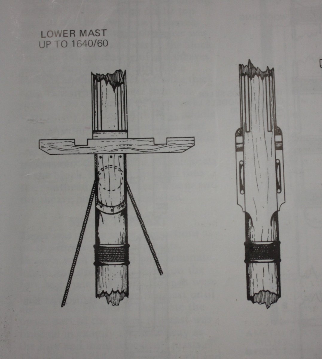
ZAZ 6786 drawing (low resolution) at RMG Collections shows the joints if you are going to make the mast of shorter pieces. Also, don't forget the taper above and below the partners. The taper ratios of the masts to the diameter at the partners are given in Lees' Masting and Rigging on page 2. (below) The main mast was about 117 feet long if you use the ratios in Lees for a first rate. If you would like the high resolution drawing of the construction of a main mast and cannot find one please feel free to PM me. It is too large of a file to attach here. Allan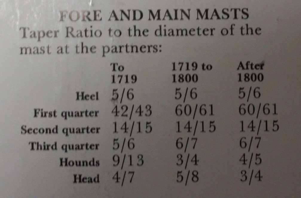
-
Hull and Deck treenails
allanyed replied to Loracs's topic in Building, Framing, Planking and plating a ships hull and deck
Dean's (Jaager)post is spot on. One rule of thumb stipulated that <the breadth of> any timber that was to be secured had to be no more than three times the diameter of the trennal, but it seems that the actual application of the rule was more flexible. In one instance two trennals were used to fasten the ship's side planking where the total sum of he diameters of the trennals was only a quarter of the width of a 12 inch plank. (Goodwin, The Construction and Fitting of the English Man of War, page 60) 1.5" diameter range should work for the hull in general so about 0.02" at your 1:64 scale. For the deck, half that size would be appropriate in most cases. If the fasteners were metal or you enjoy the look of small pox go with black trennals. If you prefer a realistic look, don't put in treenails of any kind, especially on the deck planks. If you opt to go with trennals something very subtle such as bamboo that can barely be seen would be appropriate. Allan -
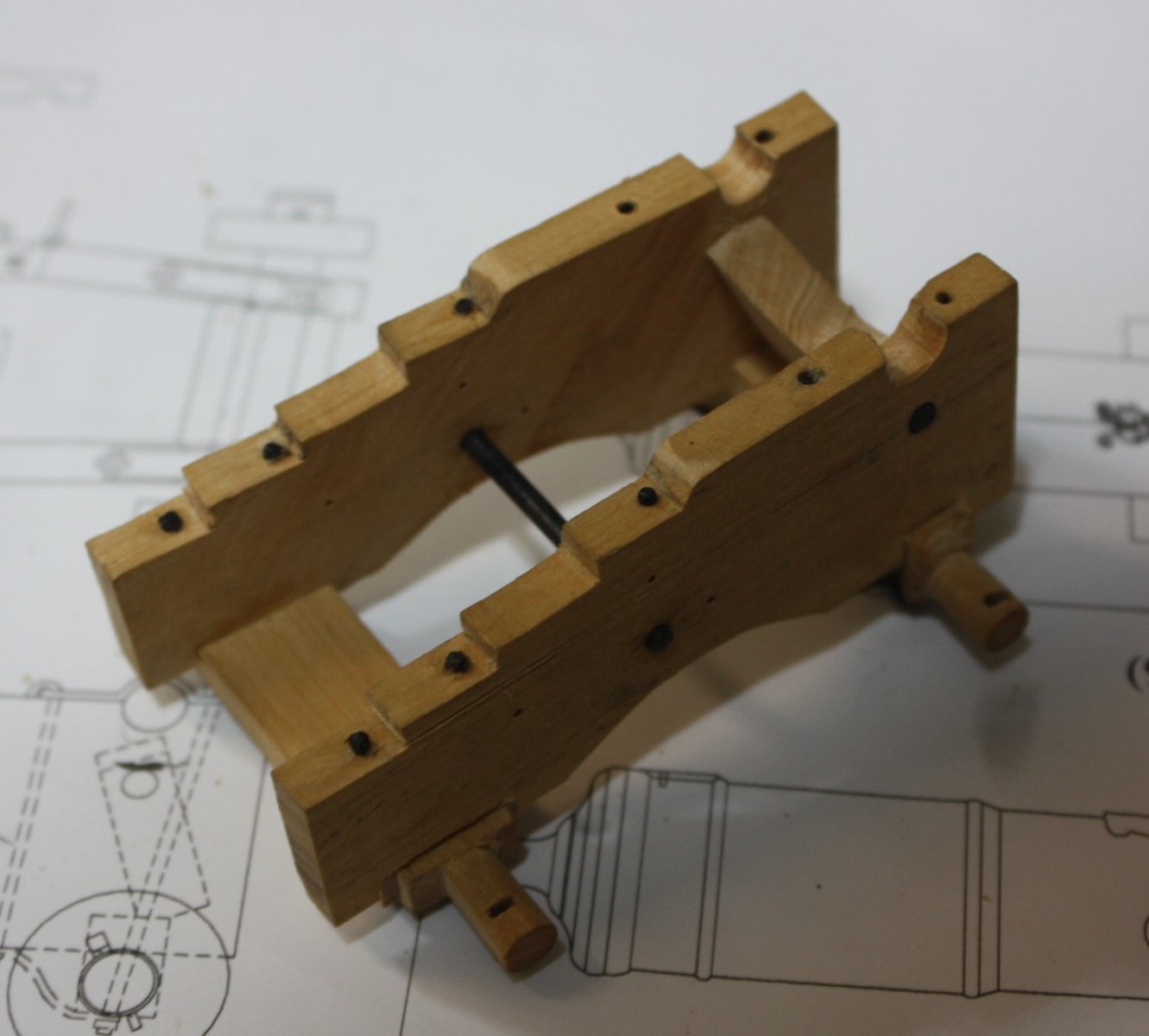
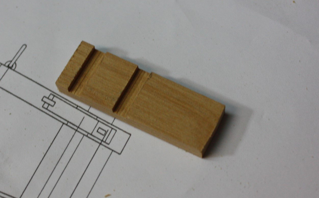
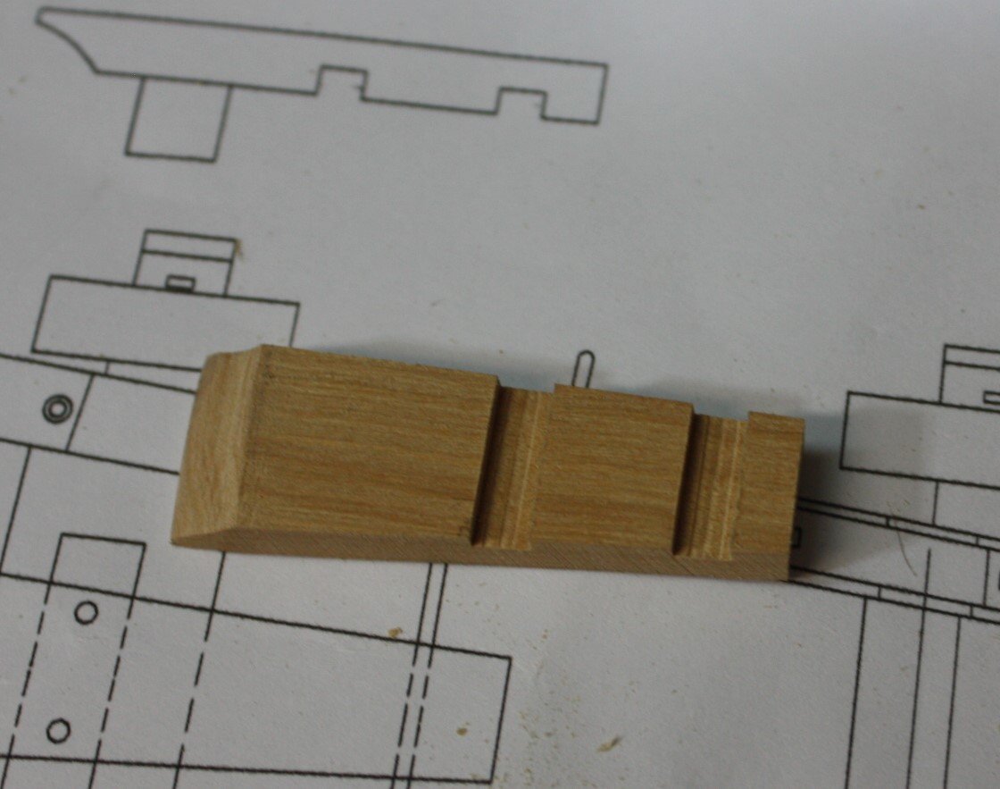
Stool bed was an easy piece to make. Even with a mill or small table saw, it is easier to work with rectangular pieces when it comes to cutting grooves so I cut mortises and such before final shaping of items like the stool bed. Photos show the stool bed and the carriage with bed bolt and various other bolts in place. Allan
-
Construction of Masts for 18th Century 'Ships of the Line'
allanyed replied to tmj's topic in Nautical/Naval History
The post from Gregory is on the mark! James Lees' book would be my choice if I could only have one rigging book for English ships from 1625-1860. There are many contemporary drawings of masts and spars on the RMG Collections site in low res as well as some on the WikiCommons site in high resolution. ZAZ6786 is a good example, albeit for a 74 of 1780. It is on the Wiki list in high resolution as well as the RMG site. https://commons.wikimedia.org/wiki/Category:Ship_plans_of_the_Royal_Museums_Greenwich It is 78 MB so I cannot post here. There are others as well in high res on their site for a lot of information on how masts and spars were built. https://www.rmg.co.uk/collections/objects/search/main mast plan for low res plans of masts. Allan -
A very warm welcome to MSW Erik!! Allan
-
Planking Book?
allanyed replied to BWDChris's topic in Building, Framing, Planking and plating a ships hull and deck
Seriously look at the three part beginner series from Model Shipways designed by David Antscherl. You will learn great skills that you can then use down the road and wind up with realistic models. Allan -
Planking Book?
allanyed replied to BWDChris's topic in Building, Framing, Planking and plating a ships hull and deck
Chris Look in the articles data base here at MSW and study the paper written by noted ship model builder and author David Antscherl. https://thenrg.org/resources/Documents/articles/APrimerOnPlanking.pdf Also, the four part video series by Chuck Passaro gives information on equally effective yet different technique. https://www.youtube.com/watch?v=KCWooJ1o3cM is a link for part 1. Allan -
Welcome Chris!! There is no shortage of help and encouragement here at MSW on your journey into the world of wooden ships. When you say take the plunge, have you ever built a wooden ship model? There are a lot of posts here on models with which to start and those to avoid for newbies. Study and ask questions even before you buy. Caveat emptor applies even in our hobby. Allan
-
Looking really good Roger. 😀 I agree with the comment from Skibe about the Lobster Smack. If the plans and instructions are followed, the Antscherl designed series and designs from Chuck Passaro are great ways to go for learning and for yielding accurate models. Allan
- 18 replies
-
- 2
-

-
- 18th century longboat
- Model Shipways
- (and 1 more)
-
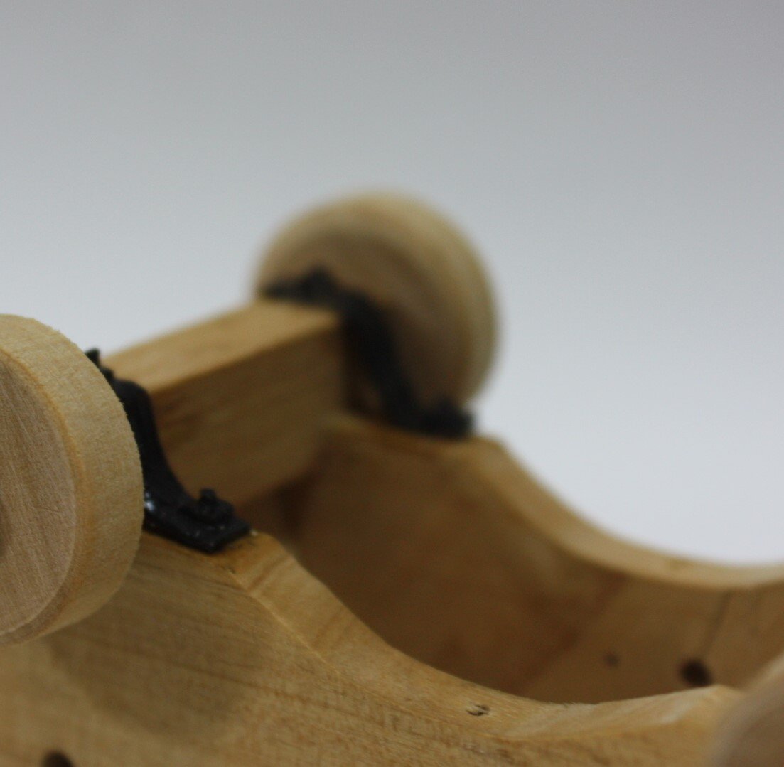
It is my understanding that screw threads came about around 400 BCE but bolts and nuts were not commonly used until the industrial revolution starting in the 19th century. In the case of the various rods on a carriage, how were the retainer pieces fitted over the rods secured? If these were not a threaded bolt and nut I am guessing one possibility is that the rod was peened over to keep the square retainer in place. Allan
-
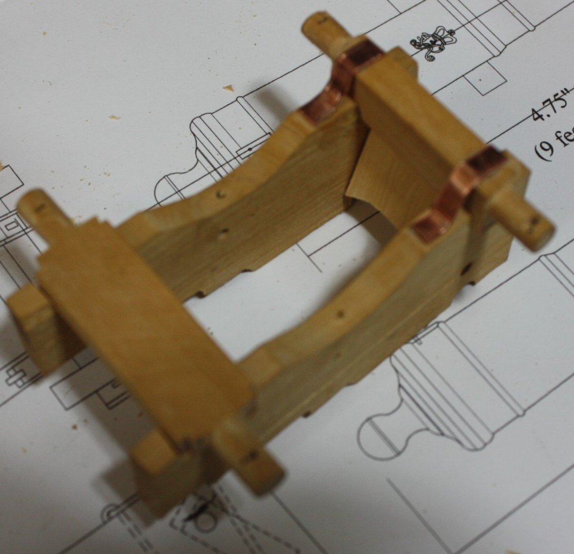
The axletrees, brackets, transom and stays temporarily in place below. The stays are made of copper rather than brass so I can blacken them in situ with liver of sulfur. In general I prefer to use copper rod, wire, and sheet rather than brass as it is much easier to blacken and can be blackened in place without discoloring the surrounding wood. Care does need to be taken to make sure any metal dust or particle have been cleaned away if there was some filing of the part once in place. In the photo below the stays have been "bolted" in place and blackened. It is difficult to see but square retainers are on all the rods. The trucks are just sitting temporarily in place in this photo.
-
Your attention to the small details is great!! I realize this is most likely a terminology thing but I THINK you are talking about the linings/port stops which were about 1.5 inches thick and were on the lower sill and the sides, attached to the frames. There may have been exceptions, but looking at contemporary models and plans there was no lining piece on the upper sill. There is an excellent description on how and when to install these so they lay correctly in The Fully Framed Model Volume II pages 69-70 . Do you mean the well in the hold? There was a door, sometimes two into the sides of the the well, so I am pretty sure waterproofing the well would not be necessary. In the following from two contemporary contracts ignore the dimensions as they are from smaller ships, but the wording may be of interest. To have a well 6 ft fore & 6ft, & 6ft thwartships, or as the draught shall direct, birthed up with English Plank of 2 ins thick of a proper height above the Ballast & from thence with weather boards, wrought looverways. To have Doors, &c. as usual ~~~~~~~~~~~~~ To have a Well 7 feet 6 inches Fore and Aft, 6 feet 0 inches thwartships in the clear, or as the Draught shall direct, birthed up with English Plank of 3 inches thick from the Orlop down, and from thence up with Weather Boards, wrought Looverways. To have Doors, &c. as usual, and to have a Cistern in the Well for a Spare Pump. Allan
-
Hi Keith Kudos to you for taking the time to replace those awful looking pieces with your own which are much better. Allan
-
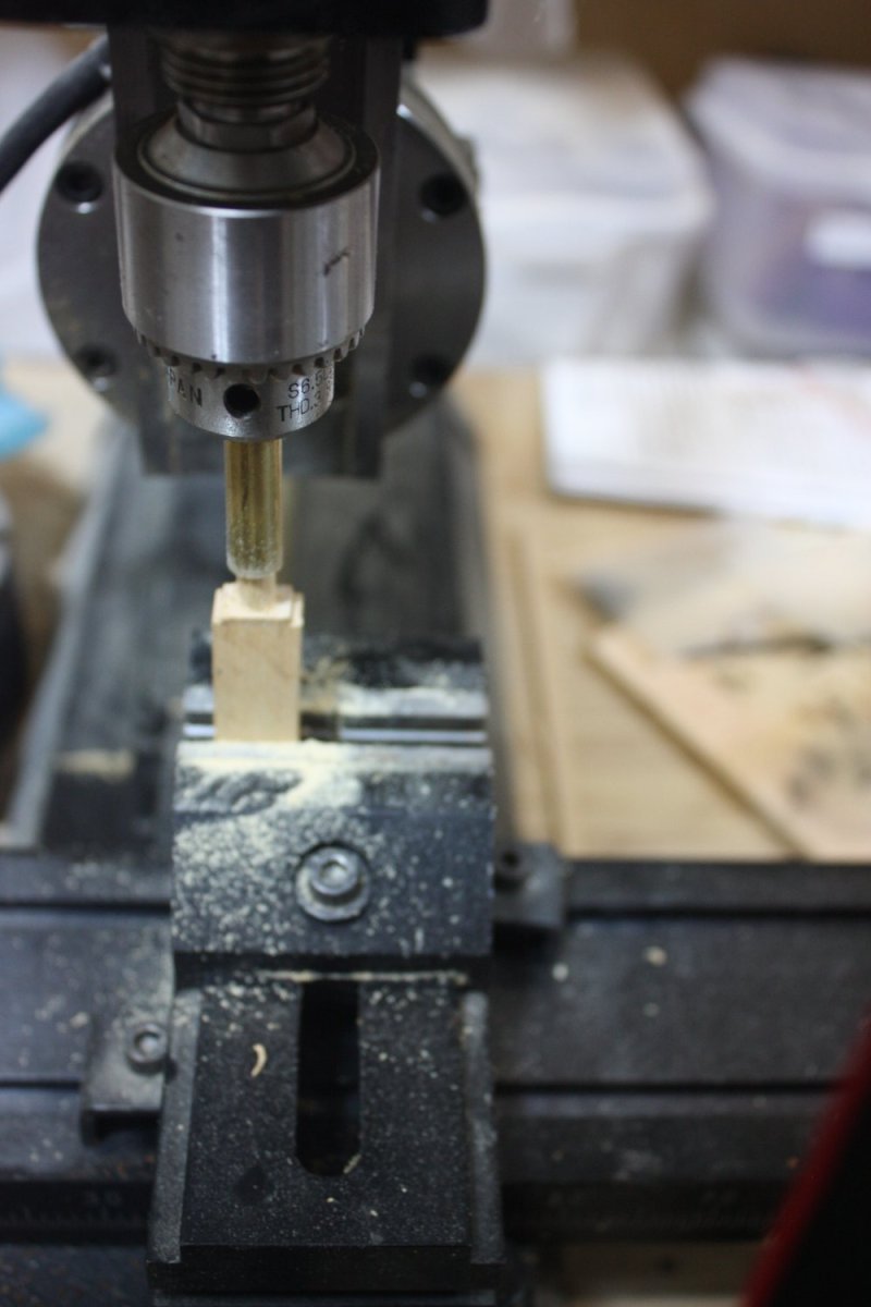
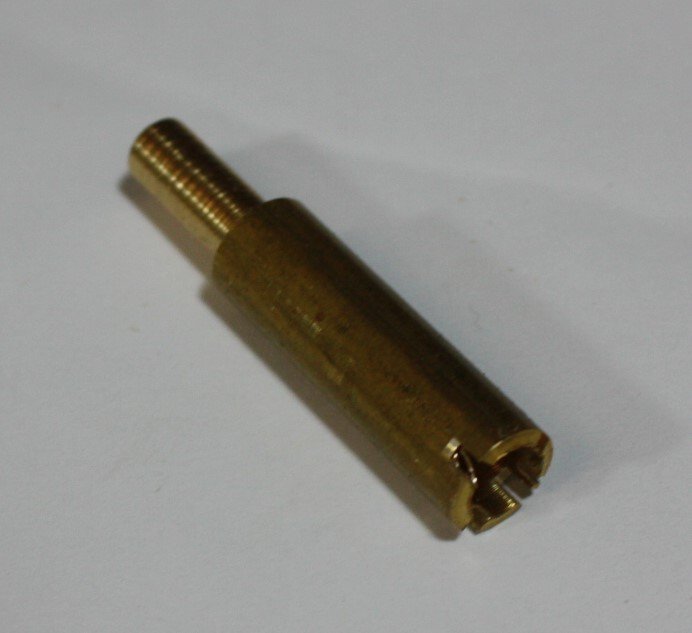
Rendering perfectly round ends on the axletrees is not difficult. There is no need to try to carve and file these, which is imprecise and takes a lot of time, especially if a project requires dozens of guns. In this case I used a piece of brass rod and a 0.25" drill bit to make an axle cutter. The hole is drilled in the rod with any type of drill and a hacksaw was used to cut small slots, creating teeth. It would be easier to cut the slots with a mill but as some folks do not have a mill or small press I wanted to show it is easily done with a hand tool. Cutting the axles themselves can be done using a hand drill, small press, or mill. First I rounded off the corners on the ends of the axles by hand to give a lead in for the cutter. The axletrees have shoulders which prevent the cutter from going too far. I made the portion to be rounded overly long for the time being.

-
Welcome to MSW! Allan
-
D What ship, nation, year are you building? When I hear battleship I think steel ships, thus virtually no rigging compared to sailing ships of earlier times. Sailing ships had dozens of sizes of running rigging and standing rigging but later ships had very few lines by comparison and could be both manilla and steel lines. At your scale a few sizes would probably suffice. Allan
-
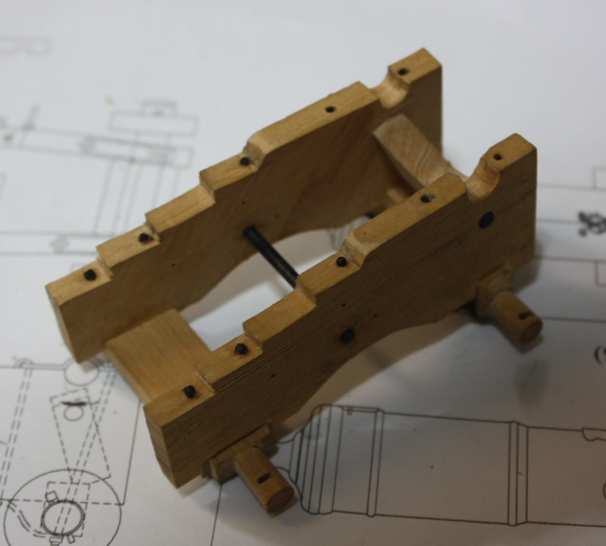
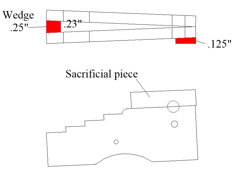
For the mortises for the axle trees, holes for the bed bolt and the cut out for the trunnions, wedges had to be made. The wedges were sized to have the brackets at the required 2 degree angle rather than lying flat. I first tried with temporary axletrees to get the brackets at the proper angle but this was not necessary. Using wedges as in the drawing below was easier and worked well. (Sorry forgot to take a photo) These openings are perpendicular to the bore of the cannon barrel so the brackets could not just rest flat when the mortises for the axletrees and drilling were done. The wedges were then temporarily glued in place with a tiny dot of PVA. This temporary assembly was then drilled and cut. Note that in order to get a properly placed partial hole for the trunnions sacrificial pieces were temporarily glued on top of the brackets and were large enough to drill a full hole, then the temporary pieces were removed. Allan
-
Replacement for 2.6x16mm screw
allanyed replied to DMM's topic in Modeling tools and Workshop Equipment
Hi D If it is not the propellor that you need it would help if you would give a bit of detail on what you are looking for in addition to the dimensions. Are you looking for socket head, round head socket drive, slot, Phillips head, Torx rounded head, flanged, brass, steel, stainless, plastic? https://www.mcmaster.com/products/screws/?s=metric+screws might have what you need. Allan -
MONTAÑES by Amalio
allanyed replied to Amalio's topic in - Build logs for subjects built 1751 - 1800
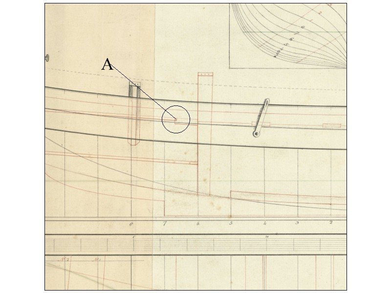
Amalio Your work is impeccable and you have shown some interesting alternatives on how to make things like the carriage trucks. Can you share your source or post the original drawings of the carriages that show the stepped joint line (Item A in the photo below), This step was new for me so interesting to see an alternative to the information I currently have on hand and I would like to add this to my current project files on these kinds of details. Thanks Allan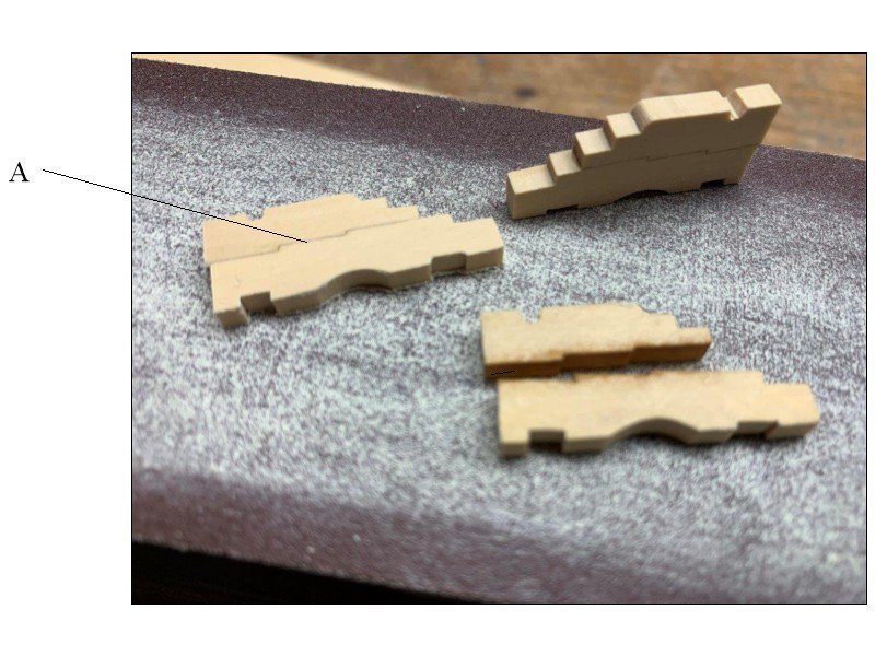
-
I suggested to Daniel that he join MSW and post an introduction about himself and his project. I will send a note that he is getting comments so should really join up, if only to clarify more of what he is looking for. If this was 50 years ago I think that with the sinkings in the war years he would have had a lot of stories with which to work. Allan
-
I received the following in an email and then "spoke" with Daniel about his project via email messages. I explained how we have over 43,000 member so MAYBE someone will see this and be able to provide some information for his project so we was very happy to have this posted. I realize we do not post email addresses so I've added the word dot in place of periods in his email address below Allan Shipwreck Survivors Project We've received the following letter from a PhD student at the University of Plymouth embarking on a timely and important new project - can you help? Do you know someone who can? Dear Nautical Researchers, I’m Dan Jamieson and I’m just starting a PhD at Plymouth University gathering oral histories of shipwreck survivors. The aim is to interview a diverse group of about twenty, from a range of different seafaring backgrounds – naval, merchant, cruise ships and liners, lifeboat, search and rescue, fishing, yachting, right down to cross-Atlantic rowers and migrants making crossings in small boats. The intention is to begin a collection of first-hand accounts that will grow over time, that will reveal the experience of shipwreck from a broad range of vividly personal perspectives. The research will preserve survivors’ stories for the historical record and help raise awareness and understanding of their experiences. This seems important at a time when familiarity with life at sea is diminishing along with the number of people who work and travel there, also at a time when empathy for seafarers in distress is not uniformly engaged. Yet as a maritime nation, seafaring remains a huge part of our history and shipping is a growing industry that brings us ever more of our worldly needs. My task now is to find people with these experiences who are ready to tell their story. If you have been on a vessel sinking at sea or if you know someone who has who might be prepared to talk, I’d be extremely grateful to hear from you. The interviews will be one-to-one, face-to-face if possible, otherwise by Zoom, semi-structured, and 60 - 90 minutes long. When the time comes, I’ll approach prospective interviewees with a preliminary call or meeting to introduce myself and explain what I’m up to. I will also send an information sheet with a more detailed run-down of the project and ask them to sign a consent form. The interviews will be sensitively and carefully conducted, subject to oral history best practice and according to a plan approved by Plymouth University’s ethics committee. If you want to know more about the project or me, please feel welcome to get in touch at daniel dot jamieson@plymouth dot ac dot uk. Best wishes and hope to speak soon, Dan Jamieson
-
A desire to build an accurate model is not a bad thing as the term rivet counting connotes, so good for you. This is an individual decision and you should be commended for giving it a go. Allan
-
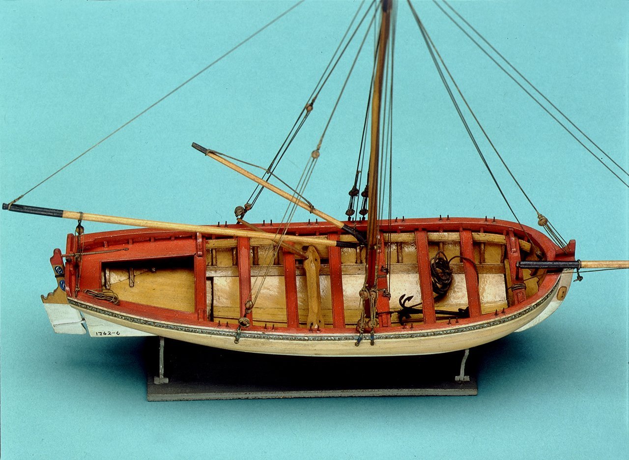
Very nice workmanship Roger! Do the plans call for the aft most thwart? Contemporary plans and models that I could find and photos of your kit box do not appear to have it so wondered if this sometimes was actually done. It would seem that a thwart there would interfere with the davit when it was in use. Below model is from RMG, SLR 0330 https://www.rmg.co.uk/collections/objects/rmgc-object-66291 I believe the side benches sat on the aft most thwart or in a mortise as shown at the circled area "A" on ZAZ5814 plan below. Again, really well done model!! Allan
- 18 replies
-
- 2
-
-
- 18th century longboat
- Model Shipways
- (and 1 more)
-
Masthead shape on early 17th century ships
allanyed replied to rcweir's topic in Masting, rigging and sails
The below is from James Lees' The Masting and Rigging English Ships of War, page 3, ISBN 0-87021-948-0, so it MAY not apply to non-combatant ships like the Mayflower. Allan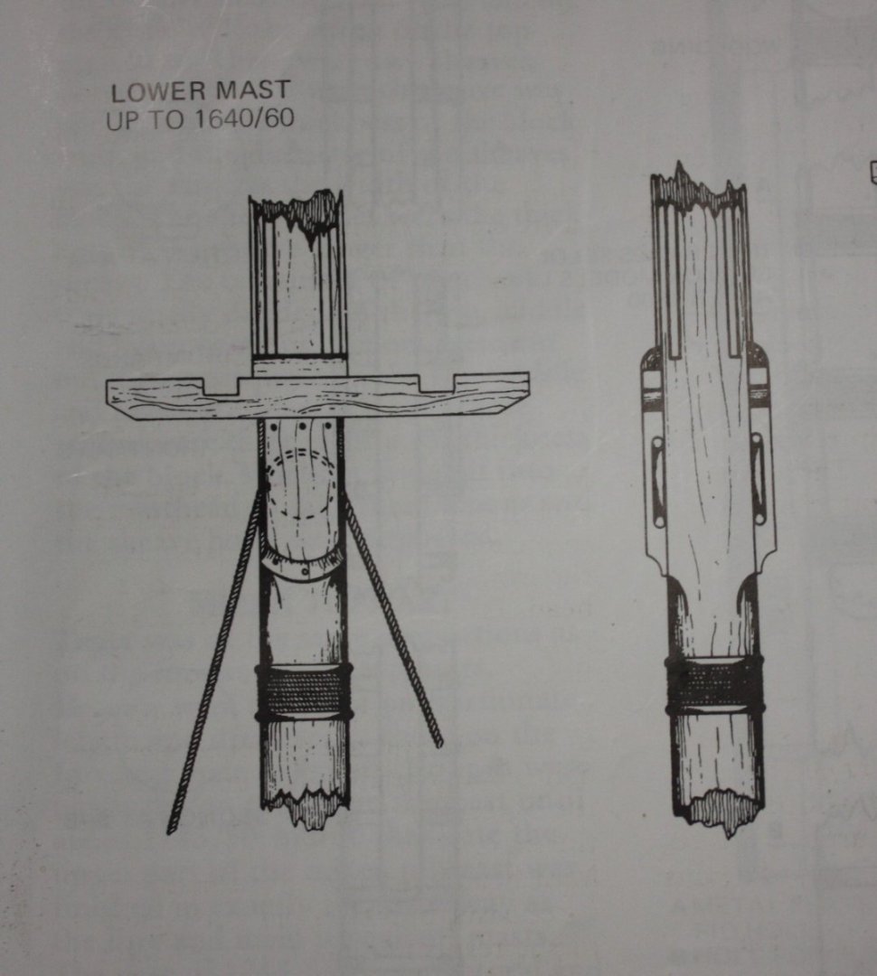
-
Thanks to you Druxey. Even if you really were an old decayed piece of timber as your name implies you have been a heck of a savior many times over for a lot of us. Cheers Allan