


allanyed
-
Posts
8,149 -
Joined
-
Last visited
Content Type
Profiles
Forums
Gallery
Events
Everything posted by allanyed
-
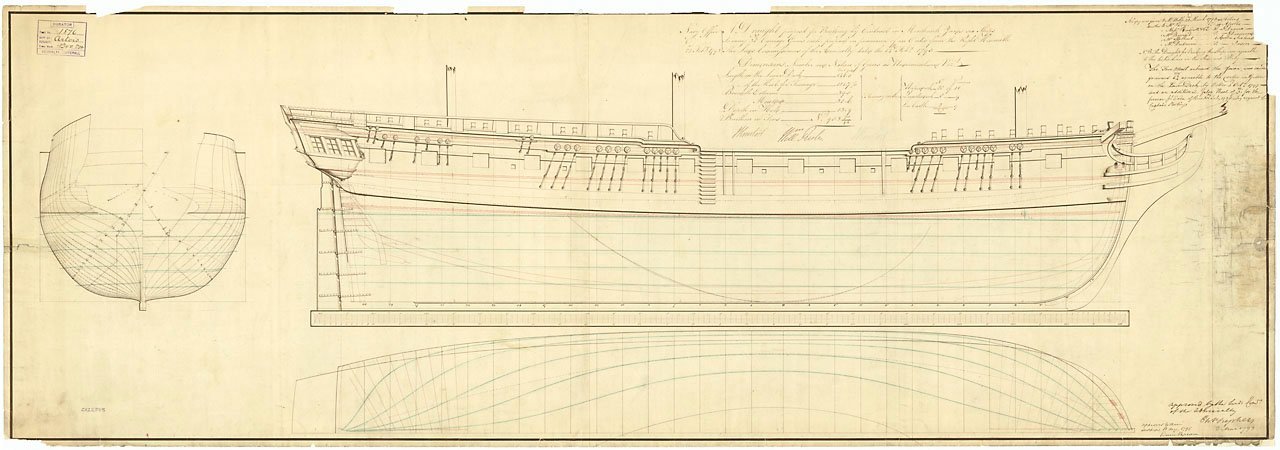
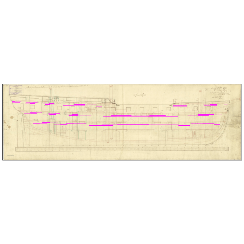
 Hi David, I think it is terminology, but not sure what you mean by clamps top and bottom. You probably know this, but in case we are talking about two different things, the clamps are thick strakes of inboard planking on which deck beams rest. As your upper deck is in place, only the QD and FC clamps would be going in. Is this what you are referencing? Pics below of Diana model at RMG, profile and inboard profile. The inboard profile shows the clamps in magenta. Note that there are too many beams on the plan as it shows original design and modified or perhaps as-built locations. Also note that the model does not show the sweep ports. The profile plan does show them. The high res versions on the WikiCommons site are easier to see regarding details but too large to attach here. Allan
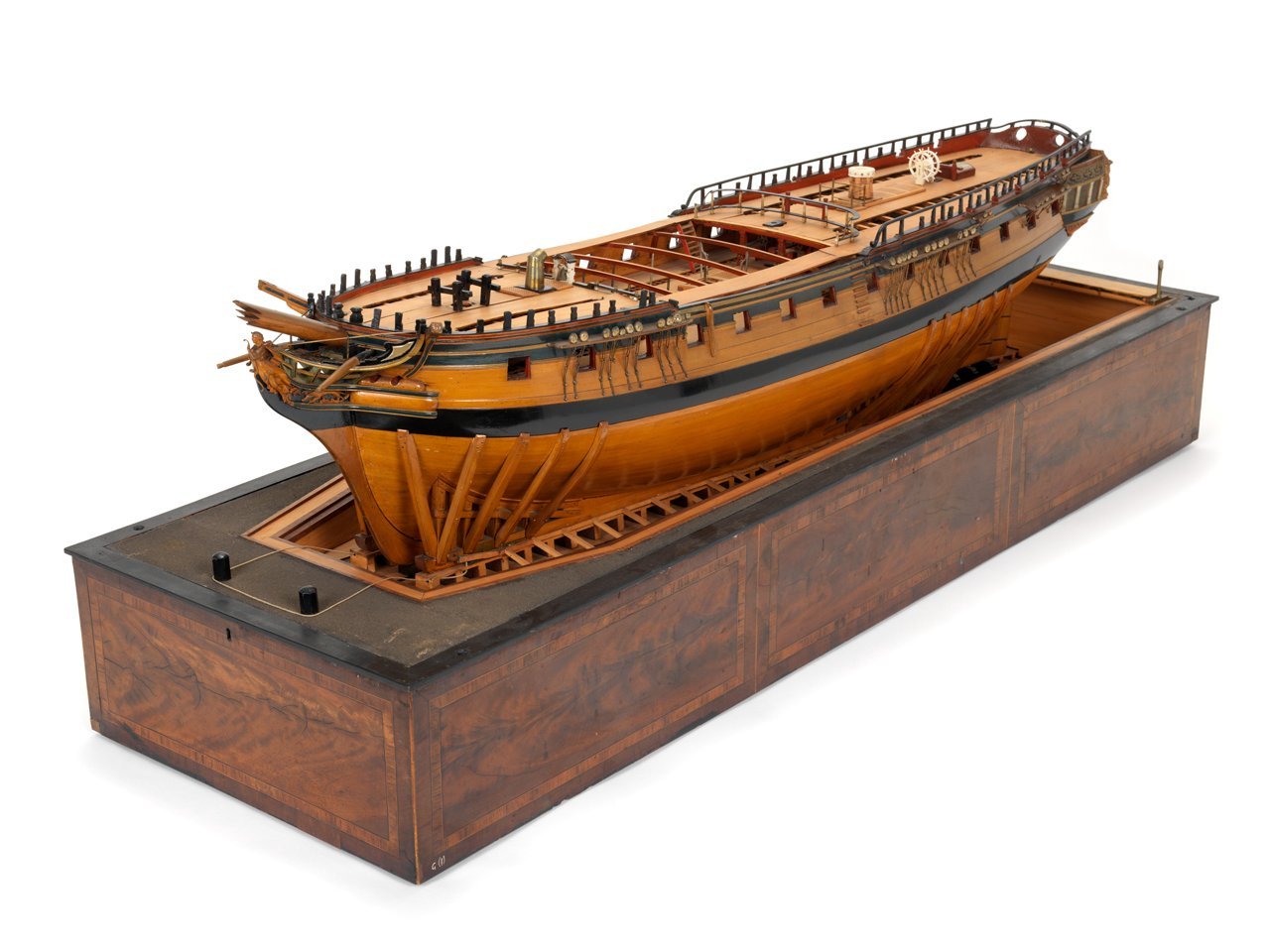
-
Strake Widths
allanyed replied to bwross11's topic in Building, Framing, Planking and plating a ships hull and deck
Do you have a nationality, era, rate or any other specifics for a ship in which you are interested? There are contemporary scantlings, contracts, models and plans from which you can get actual data if you can be more specific about what ship(s) you are considering. Allan -
Your solution sounds good to me😀 Maybe some others have ideas on this as well. The fact that you are taking care to do these things is admirable. Allan
-
HMS Victory Renovation - Outer Planking Removed
allanyed replied to Steve20's topic in Nautical/Naval History
Hi Gregory, That seems to be the consensus, but that was 150 years ago. Today may be a different story, it depends on the article one reads. One sounds dire https://www.theguardian.com/environment/2018/jun/27/are-englands-trees-disappearing and another sounds upbeat stating that there are over 120 million oak trees in the UK which "sounds" good. https://www.actionoak.org/projects/oak-trees-did-you-know#:~:text=The UK has the largest,oak woodlands covering 70%2C000 hectares. I have no idea if the size of these millions of trees mentioned in the second article are useful for ships, but given time...😀 Allan -
I realize most observers would never notice the difference or even realize something like this was of any consequence but as it matters to you, is there any local veneer supplier nearby? There is Nantwich veneers in NW England, so a bit far for you, but maybe worth contacting. 0.5mm veneer seems to a pretty common size and would be closer to the desired 0.6 than 1.0mm. Rather than wood, maybe measure some cardboard backing from a tablet or something similar to see if it is closer to the 1mm wood. I just measured a couple pieces of card from two different notepads and both were a tick over 0.5mm. Add the red paint and you are really close. As the side linings are somewhat trapezoidal when finished it is easiest to make them oversize and then trim. That being the case, I think wood will be easier to trim and sand flush with the inboard planking compared to card stock, but it might be a good alternative to try. Cheers Allan
-
Looking good! I typically do the same thing, drilling a series of holes then cleaning up with knife, files, and sandpaper stick. Just remember the stops/linings are only about 1.5" thick (0.6mm at your scale). Allan
-
That is correct. Ideally it will land on a bulkhead so if it is a little forward or aft of 35mm it should still look about right.
-
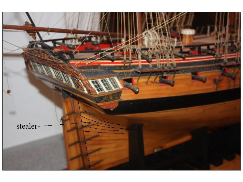
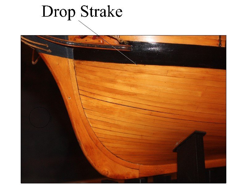
This is not correct. In the drawing and model in post #13 above, they are about 7 scale feet from the bow. On the 1:48 scale contemporary model above it is about 1.75" (44mm) from the rabbet. I have no idea what your scale is, but if it is 1:64 for example, a drop strake would be about 35mm from the rabbet. I am pretty sure there is no way to tell where you will need a stealer aft or drop strake forward until you are doing the planking. Looking at the models and drawings, they appear to always be one or more strakes below the lower wale. Regarding the Endeavour photo that Hornet posted above, the drop strakes are mirrored together and are different than anything I had seen before. It obviously works but is this style a modern convenience or was this done in times contemporary to the original Endeavour or other sailing ships of the 17th-19th centuries. Below is a stealer at the stern on another contemporary model at Preble Hall. I highlighted it as the photo I took was not very clear. It is the Leda or Phoenix 1783. Allan
-
Strake Widths
allanyed replied to bwross11's topic in Building, Framing, Planking and plating a ships hull and deck
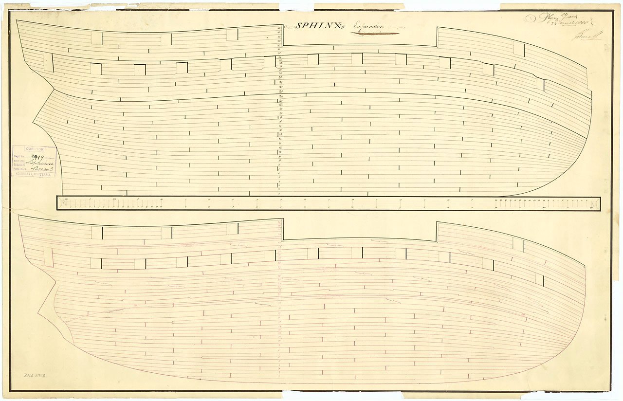
Druxey's post is spot on. There are a few planking expansion drawings of later 18th century ships such as Sphinx 1775 and Squirrel 1785 that show every plank inboard and outboard. Sphinx plan is below but it does not necessarily apply to other size ships or different eras. There are also contemporary cross section drawings that show the breadth of planking at midships for various size ships and eras. The cross sections do not account for the broadening of the planking aft or the narrowing moving forward. Allan
-
Hi Mark and Luigi, I cannot find any contemporary models or plans with that configuration so far. What I have found are like the following. One model example from Preble Hall is below showing a drop strake nearer to the bow. It is about 7 feet from the rabbet on a 36 gun ship with a length of 137 feet. The contemporary planking expansion drawing below of Sphinx 1775 shows a drop strake about 8 feet from the rabbet. Upper plan of the two shown is outboard planking.
-
Considering the material that was provided, you have done a credible job on the planking. I believe the above comment is correct though. It may just be the photos, but it looks like the wood you are using is not appropriate for a ship model. It might be too late for this project, but if you want to achieve planking as shown in the videos you mentioned, consider using a wood that has better qualities for ship modeling. Allan
-
Ciao Luigi I cannot access these links. Is anyone else able to see them? Please post photos Luigi. THANK YOU Allan
-
Next NRG Conference
allanyed replied to YankeeClipper's topic in NAUTICAL RESEARCH GUILD - News & Information
Huge applause to those that organize the conference as I cannot imagine the work that goes into organizing such an event and hoping there are enough attendees to make it worth all that effort. But, is covid the reason to cancel?? Regardless, 'tis a shame. -
That is absolutely great advice. In my modest library I only found two sources that addressed the coppering, but as with so many things in our hobby, there is very often another source that contradicts the others. It seems that there are very few absolutes in our hobby. 😀 Now it's time to go find a copy of British Warships in the Age of Sail 1714-1792 to add to the library. Thank you for that lead Chris, it is very much appreciated! Allan
-
Looks that way. As you write in your signature, you'll just have to make them yourself, and we won't mind the complaining😀 Allan
-
HMS Victory Renovation - Outer Planking Removed
allanyed replied to Steve20's topic in Nautical/Naval History
Steve, These picture are wonderful. The smallest details like the inset of horseshoe and dovetail plate can be seen and are extremely useful pieces of information for any modeler. Allan -
Lovely construction Eck! Your model brings up a question for me. Would the Pegasus have had copper sheathing? She was launched in 1776 and lost in 1777. According to Goodwin in The Construction and Fitting of the English Man of War page 226 copper sheathing was tried on a couple ships in the 1760s with disastrous results so then shelved until the late 1770s and was not a general practice until 1782. From The Fully Framed Model, Swan Class Sloops, Volume II, page 31, sheathing became a requirement for frigates in 1779, (two years after Pegasus sunk) and on all new ships starting in 1782. Was Pegasus perhaps an exception?? Allan
-
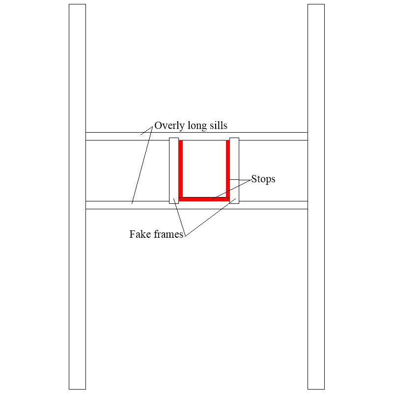
Maybe you can make a box for each port that would be the equivalent of the sills and what would be frames. The sills can be overly long to fit between the bulkheads or your filler pieces. The following is just a quick sketch of one imaginary solution but others may have found better solutions. Allan
-
Hi David Adding to Jason's fine photos, note that when you do get to making the ports remember the port stops (linings) were normally on the sides and bottom, not the top of the port. They are set back to be even with the outboard edge of the frames/bulkheads so the lid can close properly and be aligned with the planking. There are photos of a number of models here at MSW where the linings are sticking out beyond the sills and frames and very thick, even though this was never done in real practice. There is an excellent description and set of drawings in The Fully Framed Model by David Antscherl in volume II, pp.69-70 regarding the port stops which he also mentions these were about 1.5" thick (0.6mm at your scale). Couple more pictures below are also of a contemporary model at Preble Hall and describes better than words. Allan
-
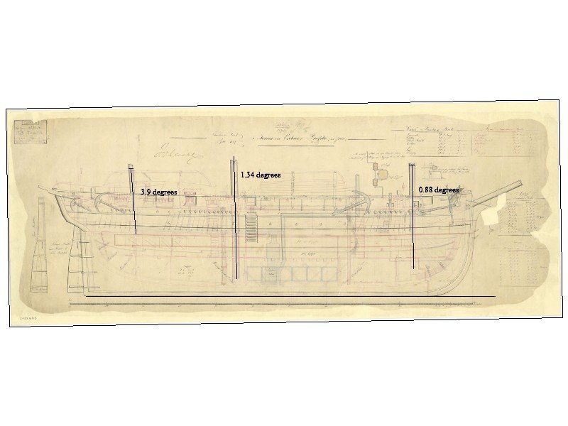
Each mast is raked at different angles and there is a bit of adjustment possible on the real ship with the mast partners and wedge ring. You can see the angles on contemporary plans and models. There are 10 contemporary low resolution plans of Terror 1813 in the RMG Collections site. https://www.rmg.co.uk/collections/objects/rmgc-object-85464 and many of them in high resolution on the Wiki Commons site on page 17 Go to https://commons.wikimedia.org/wiki/Category:Ship_plans_of_the_Royal_Museums_Greenwich and then go to page 17. If accuracy is of interest, study all of the drawings as they are a wealth of information. See below for mast angles. Allan
-
This model looks quite nice and your workmanship is super. As a point of interest, not at all a critique, according to James Lees in The Masting and Rigging of English Ships of War, page 2, iron woolding bands did not supersede the use of wooden bands, until 1800. As Sphinx 1775 served in the RN until 1811, (except for when she was French for two months in 1779), iron bands may very well have been in place in the latter years. Allan
- 426 replies
-
- 1
-

-
- Vanguard Models
- Sphinx
- (and 1 more)
-
David, Guns are part of the ship design equation when it comes to room to get them on and off the ship, operate them and consider the effects of their weight in their given locations. Those are the few that come to mind. Others may have more 😀 Allan
-
Most contemporary models do not include cannon of any kind as they were not usually built for decoration. We are a different story, so most of us like to include guns in spite of the agita created by rigging them. For display purposes, it is probably more important that they are consistent, that is depressed, elevated or centered. Looking at a number of photos I took of models at Preble Hall, most of the models that did include cannon had them all centered. I do not know if these guns were on the original models or added in modern times. Allan
-
Hi Dan, I assume you searched the Mystic sets of plans, and I wondered how many were useful to you, if any, https://store.mysticseaport.org/ships-plans/catalogsearch/result/index/?cat=129&p=1&q=whale+boat&x=0&y=0 There are 161 sets of plans, perhaps one of them will be what you are looking for. I for one am curious to see if any of their sets of plans include the proper boat for the Essex (Pequod). The New Bedford Whaling museum may also be of some help. https://www.whalingmuseum.org/ Allan