allanyed
-
Posts
8,149 -
Joined
-
Last visited
Content Type
Profiles
Forums
Gallery
Events
Everything posted by allanyed
-
 Thanks Pat. It SEEMS that the second eye and the furthest eye on the bulwark would be available for training the gun fore and aft in place of or in addition to the use of spikes, especially for the heavier guns as noted by Gary above. Allan
 -
I would be surprised if basic rigging of guns varied that much in a given era. As to going back to confirm, the George Orwell unit went forward and backward so may be a good choice as well as the Wavelength Acceleration Bidirectional Asynchronous Controller (Wabac machine.) Allan

-
Decorative trim/rail
allanyed replied to DaveBaxt's topic in Building, Framing, Planking and plating a ships hull and deck
Phew!!!! Thank goodness
-
Incredible! I knew you were not far from Carrara and Pietrasanta where Michelangelo got his marble but I did not realize such artistry was in the air there as you surely got those skills in your blood. Allan
-
Great point Greg. But, if the figurehead is filled in between the legs a little, it will help it from looking like it is riding a horse.😀
-
If speed is your requirement, ship modeling may not be the right hobby choice. 😀 As to more accuracy I do not agree. I just did some experimenting using a one inch long gage with clean rope and also measured rope with glue once my eyes stopped watering from the fumes. Clean rope designated .035" had 27 raps -0.037. Preglued rope measured 0.038" I also measured rope designated 0.08" and it had 13 wraps (0.077") for clean rope and a piece that had been soaked in glue which measured. 0.085" Allan
-
Decorative trim/rail
allanyed replied to DaveBaxt's topic in Building, Framing, Planking and plating a ships hull and deck
Please don't ruin a chisel. There are several different rails on most ships, often 6 our more. A stiff back razor or a piece of an old hacksaw blade works beautifully. Chuck a thin abrasive wheel in your Dremmel and then grind grooves in the blade to whatever shape is appropriate for any given rail. When making the rail itself, multiple shallow drags/cuts along the length of the wood to be used is easy to do MOST of the time if you use an appropriate wood. Tight grained species rather than the open grained woods often seen on builds is the way to go. Open grained woods will make the adventure more difficult and often times does not look as good in the end. Allan -
All of what you wrote makes a lot of sense Eberhard, but including the information at least gives the builder a choice of adding some realism or not. Will they succeed? Who knows, but nothing ventured, nothing gained. 😀 If nothing else it can add some new knowledge even for those that feel such details are unachievable or not worth the effort. Allan
-
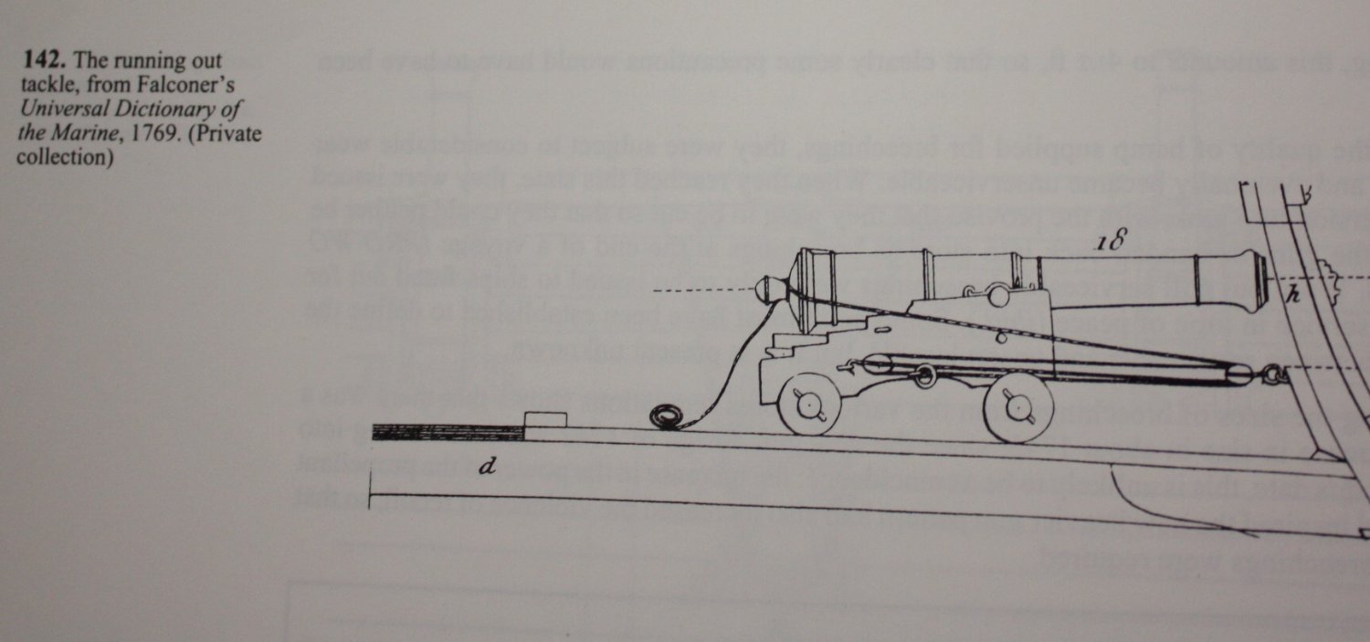
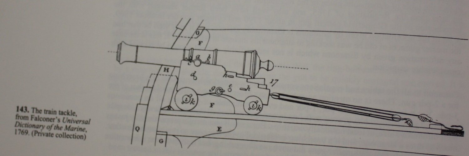
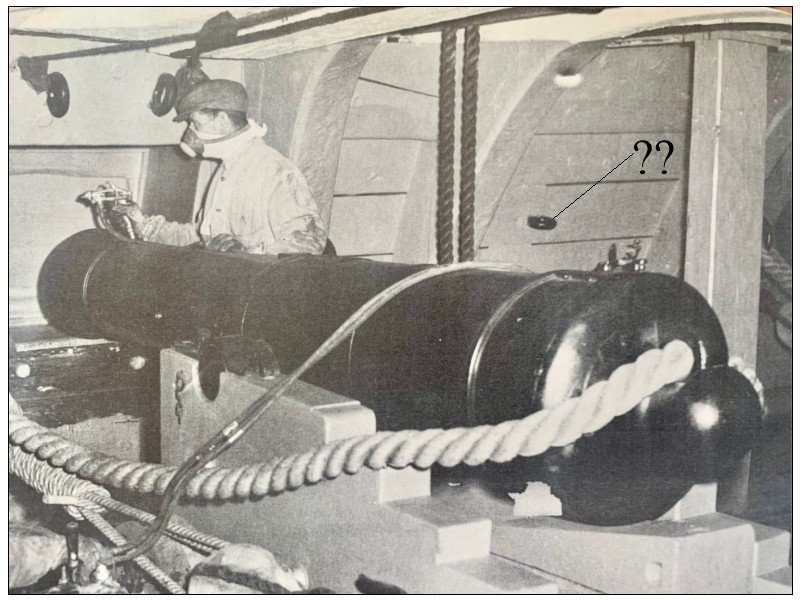
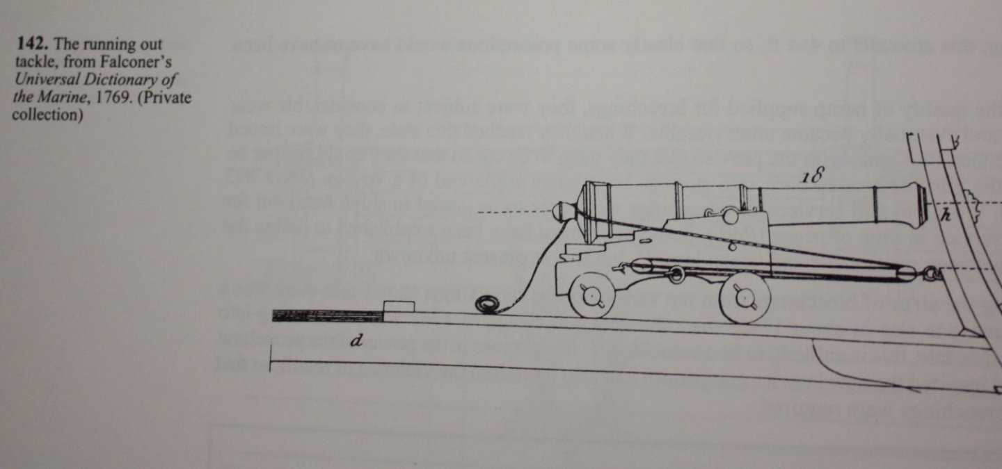
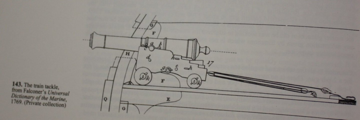
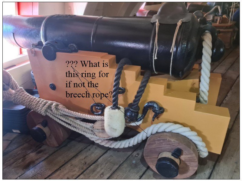
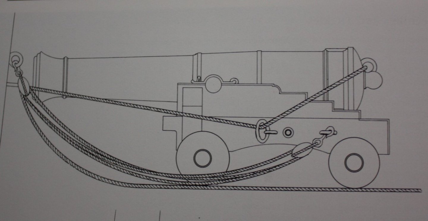
Morgan, Are you referring to the ring identified below with a question mark? Looking at various drawings the training tackle(also called relieving tackle) ran from the breech end of the carriage inboard, not to the hull. It is my understanding that training (aiming) the guns was done be elevating or depressing using the wedge and using leveraging poles and such under the carriages to shift them sideways when needed. There is some question in my mind about the identification of the rings in the first drawing in post #43. The port tackle was used to raise and lower the gun port lids (line# 4) Then it shows rings in the hull (#7) called port tackle eyebolt which make no sense, at least to me. Lavery gives a verbal description for rigging the ports and the variations over the years on page 139 of The Arming and Fitting of English Ships of War and it does not jive at all with the above drawing. Line #4 in the above drawing should run to a block in the beam above, not down towards the deck. The drawings below are from Falconer's Universal Dictionary of the Marine, 1769 and are show on page 386 in Caruana's English Sea Ordnance. volume 2. It seems there are different terms for the same item being used by whoever did the first drawing shown in post #43, and others such as Falconer. I have no idea if one or the other or all of them were in common use back in the day. Allan
-
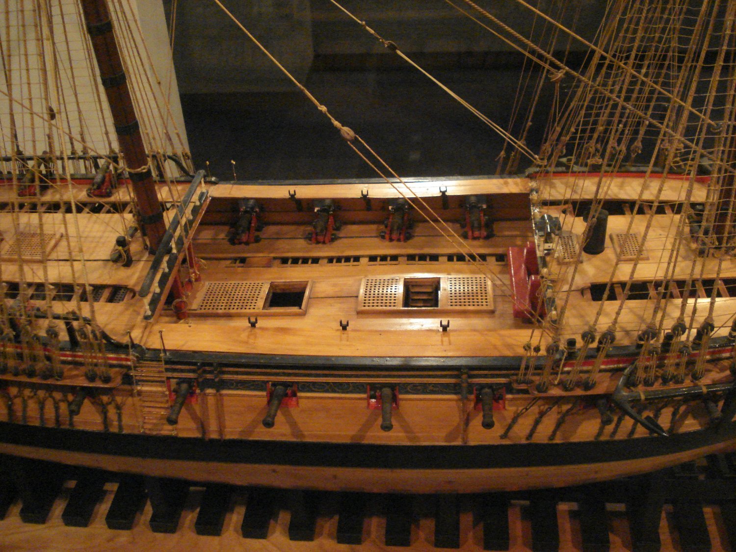
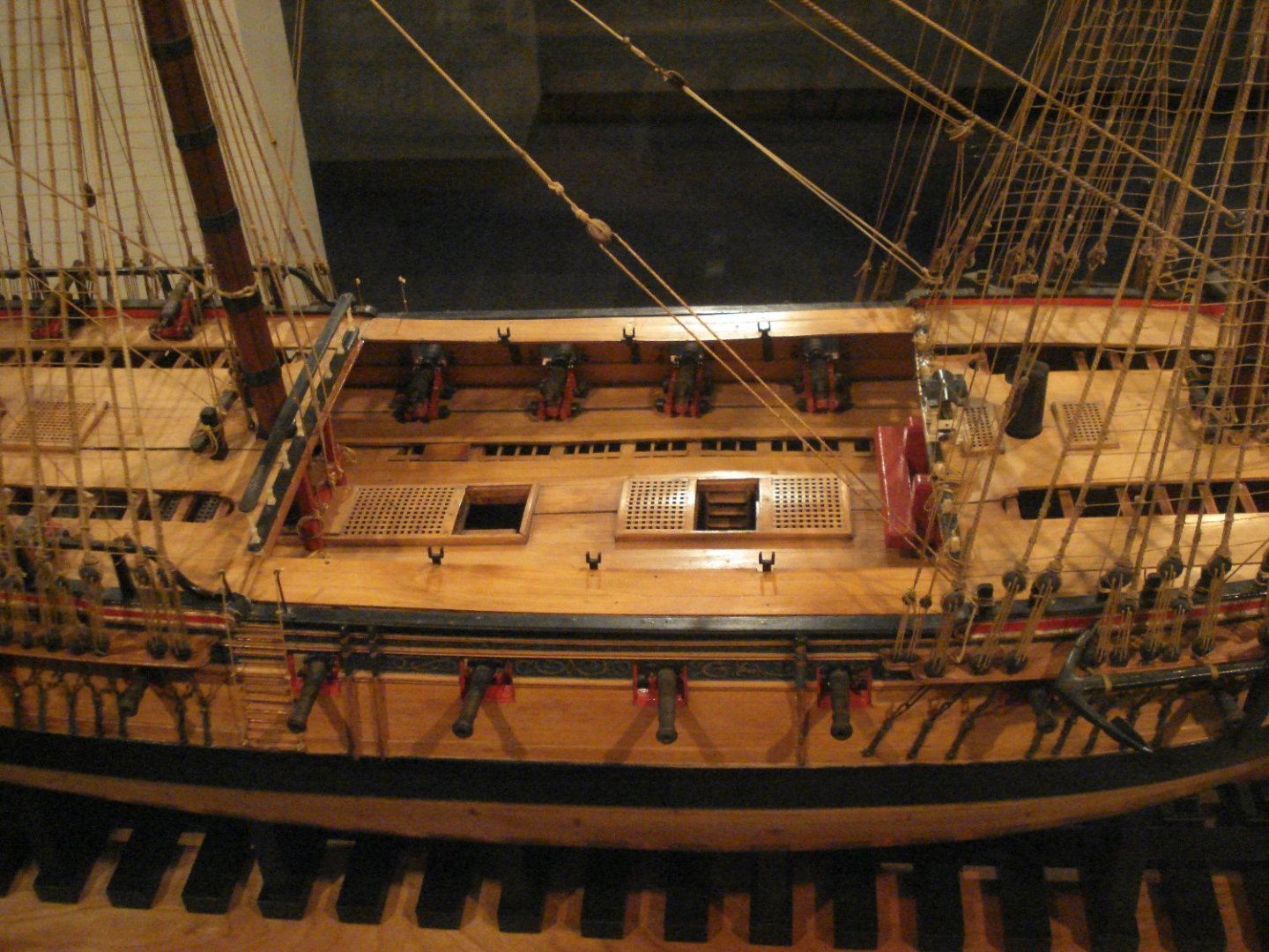
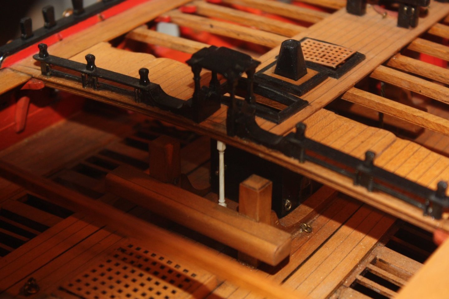
While the train tackle is not shown in these photos it is Interesting that the last photos show only one ring for the train tackle while the first photos show three. Maybe there are too many inconsistencies on all these replicas to trust them without a good bit of research into contemporary based sources. Allan
-
WELCOME DIEGO! Take the advice of the person from post #5. This a great way to learn good habits and appreciate well designed kits. Allan
-
Thanks again Steve, much appreciated.👍 This last carriage shows 3 rings at the breech end of the carriage. One would be for the train tackle. What are the others for? I cannot find any contemporary information showing three rings at the breech end of on any carriage, again making use of these reproductions as answers to any kind of research of questionable value. Perhaps some member can post contemporary based information regarding the need for three breech end rings on the carriages. Allan
-
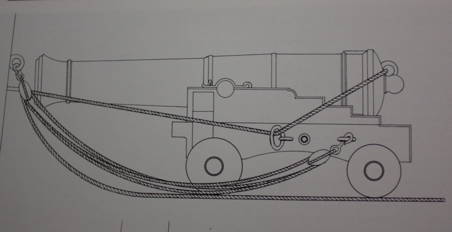
Hi Steve, thanks for posting these pictures. There are doubts that these are faithfully reproduced. For example, the breech rope does not pass through the loose ring as is seen in various contemporary based sources for rigging guns. If it does not to pass through the ring, what is the ring for? Drawing is showing 1795 carriage pattern (From Congreve) Allan
-
Eagle Emblem
allanyed replied to _SalD_'s topic in Discussion for a Ship's Deck Furniture, Guns, boats and other Fittings
Just PM'd you the entire page in DXF so you can edit as you wish. If the X and Y axes are not exactly right for you, you can compress and/or stretch as you wish or trace over the image and then compress and/or stretch the new drawing to what ever works for you. Allan -
Denis, You have made the point very well. Most modelers, including many MSW members, are not aware of these kinds of things and assume every kit is accurate and as most of us have learned over the years "assuming" anything in life is fraught with danger. There are many Establishments, contemporary plans, models, contracts, as well as books based on contemporary sources to learn about many of these kinds of details. With the information in hand the model builder can decide if she/he wants to go the extra steps or not. Allan
-
Eagle Emblem
allanyed replied to _SalD_'s topic in Discussion for a Ship's Deck Furniture, Guns, boats and other Fittings
Regarding the head facing to the eagles right, found this bit of information as to why The Presidential seal is an example of heraldry, the ancient art of symbols of nobility. Everything on a Herald has a meaning, even the colors. In heraldry, “right” (as a direction) is more noble, or honorable, than “left,” which is less noble, dishonorable, or inferior. The Latin word for Left is “sinister,” which in English means devious or untrustworthy. Allan -
Hi James I would go further and bet that most builders are not aware of this design feature that existed on most ships, so whether they would care or not really cannot be determined with any degree of confidence unless polled. Maybe my poor wording in the first post so my apologies, but my question is why these basic design features are ignored, not how many people would or would not find it important. Hi Chris, Kudos for showing this on Indy!!! Great to see another little extra on what are already exceptional kits. Cheers, Allan
-
Eagle Emblem
allanyed replied to _SalD_'s topic in Discussion for a Ship's Deck Furniture, Guns, boats and other Fittings
Any of these help? I can PM these to you in DXF if you have a CAD program. Allan Eagles.PDF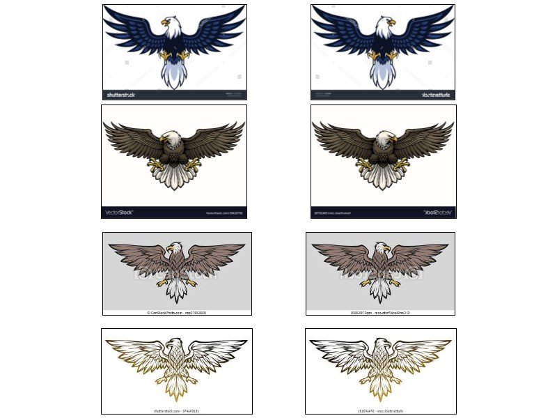
-
Ron, Your model continues to go beautifully. The gun and carriage look good. Lots of little blocks and such! Will you be darkening the breech rope so it is more of a tan color and/or using miniature rope? It is probably just me but the white color of the breech rope seems to be a bit stark. Cheers Allan
-
Other than the kits designed by Chuck Passaro, do any other kits address the large amount of tapering of the subject parts? This seems to be very basic design criteria as the dimensions are detailed on the various scantlings sources including the Establishments, Steel, et al. and are significant. For example the stem tapers about 30% from top to bottom at the keel and the knee of head tapers more than a very noticeable 50% fore and aft from where it meets the stem to the place for the figurehead. Why is this shaping not done on the parts in other kits, or, at least described in the instructions so the builder can do it themselves if it is a cost factor? Allan
-
Decorative trim/rail
allanyed replied to DaveBaxt's topic in Building, Framing, Planking and plating a ships hull and deck
Kudos!!!!!!!! Allan -
Mr. Papa I built a model of her for a client two years ago and did a complete set of drawings based on drawings from RMG, discussions which Richard Endsor, drawings from Mr. Endsor's books and various other books from Goodwin & Lavery, as well as a contemporary contract of a similar ship from 1676. There is short build log here at MSW if you are interested. https://modelshipworld.com/topic/28125-17th-century-british-galley-friggot-by-allanyed-164/ If you are in need of any or all of my files, please let me know. Allan

- 4 replies
-
- 12
-

-
I see what you mean. I had not seen any of the clamps as a decorative strip/molding before as it is really just a thick plank but why not have a little showiness😀? FWIW the forecastle deck clamp on a 38 according to the Elements and Practice of Naval Architecture and The Ship Builder's Repository is 4" thick compared to the planking above and below at about 2" thick. Rather than being decorative, in the former, it is bearded down to 3" at the lower edge. For the QD, the clamp is 4" thick and bearded to 3" in the Elements and Practice of Naval Architecture and 3.5" in the S.R. In all cases the breadth is to be such that it works down to the upper deck gun ports as shown in the photo in post #85 by Dave Baxt. Regarding skid beams this is a new configuration for me as well. I had always seen them as in the photos below on contemporary models. Goodwin shows them as well on page 210. DaveEN can you share the source of the design in the photo above? Hope all of this is a little help. Allan
-
Very nicely done Gregory!!
-
Strake Widths
allanyed replied to bwross11's topic in Building, Framing, Planking and plating a ships hull and deck
Maybe look at the scratch build logs for some ideas. The techniques used in scratch builds are sometimes applicable to kit builds. Allan