


allanyed
-
Posts
8,149 -
Joined
-
Last visited
Content Type
Profiles
Forums
Gallery
Events
Everything posted by allanyed
-
Inexpensive and effective! I do hope you bring this to the October conference to see how you set it up. Thanks Allan
-

Does This Wood Model Ship Have Any Monetary Value?
allanyed replied to jtridexter's topic in New member Introductions
HI Dexter If it is a family heirloom the value to you is what you put on it. If you are thinking about a monetary value you might try a garage sale or post on Ebay or similar site and hope there is someone that likes the look of this vessel and does not remember the quote often attributed to P. T. Barnum. Allan -
Books to learn Fusion 360
allanyed replied to allanyed's topic in CAD and 3D Modelling/Drafting Plans with Software
Thanks everyone! Allan -
Stem/Apron depth
allanyed replied to Matrim's topic in Building, Framing, Planking and plating a ships hull and deck
Hope the following is helpful, The following is from Steel for a 32 STEM To be moulded 1' 3" to be athwartships or sided at the head 1' 7" And to diminish from the head to the lower side of the lower cheek to upper cheek To be sided at the keel 1'1" (same as the keel at the fore end) APRON- The false stem, or apron, to be 8.5" thick (SR gives 9.5") broad as the stem if rabbet is in the middle, otherwise 1' 7" To give proper shift to the scarphs of the stem, and the scarphs to be 1' 2" in length (SR - 10.5") Allan All the scantlings from the 1719 Establishment through Steel's Elements and Practice can be found in Scantlings of Royal Navy Ships at Seawatch Books. Allan -
Books to learn Fusion 360
allanyed replied to allanyed's topic in CAD and 3D Modelling/Drafting Plans with Software
Thanks Kevin. I was hoping for a book, but will give this a try. Cheers Allan -
Can anyone recommend a book to learn Fusion 360? There are on-line vids and there are a number of books but I would like your recommendations based on which book worked for you. Many thanks Allan
-
Hi Michael, The Establishments (1719-1750) only give the thickness and do not include a 16. The closest is for a 20 gun and gives the main wale at 2' 10" deep and 5" and the strake above the wale at 4" thick but gives no width. The strake under the wale is also 4" thick. The Shipbuilder's Repository 1788 shows one strake of thick stuff above the main wale for an 18 gun, 98' 5", 300 ton sloop of war. The thickness is 3.5" and is 12" broad. The Elements and Practice of Naval Architecture 1805 gives the strake above the main wale at 3.5" thick by 10" broad. For a 16 gun 273 ton 78' cutter the The Shipbuilder's Repository shows 4"X11" and The Elements and Practice of Naval Architecture shows 3"X10" Hope this is at least a little help for you. Allan
-
Hopefully we will have well over 100 different barrels in 3D later this year. Working with the mods on a way to do this so all will be posted in the Articles data base. The drawings are in full scale but I made a spread sheet with LOA dimensions for each barrel in 7 different scales. It is no problem to do them in any scale, but the spread sheet makes it a little easier not having to do the math. Allan
-
I think it is me not being clear, my apologies. I think it is mostly a matter of terminology. The pic below should help a little even though it is not the same ship. Allan
-
Stem/Apron depth
allanyed replied to Matrim's topic in Building, Framing, Planking and plating a ships hull and deck
The same tapering can be found in the scantlings in Steel's Elements and Practice of Naval Architecture 1805 and The Shipbuilder's repository 1788. The following are the dimensions for a 32 gun. Allan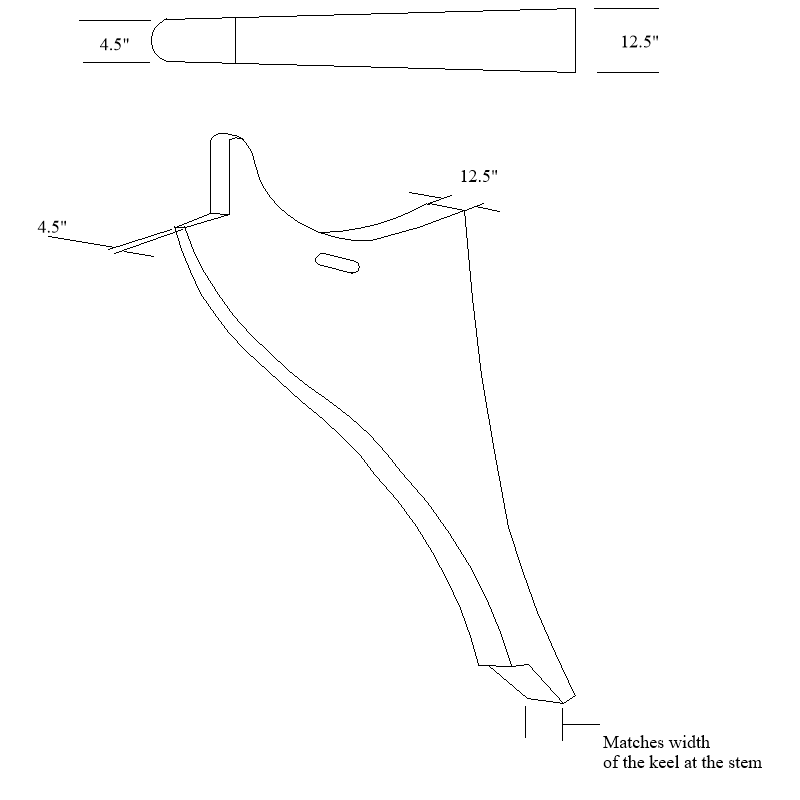
-
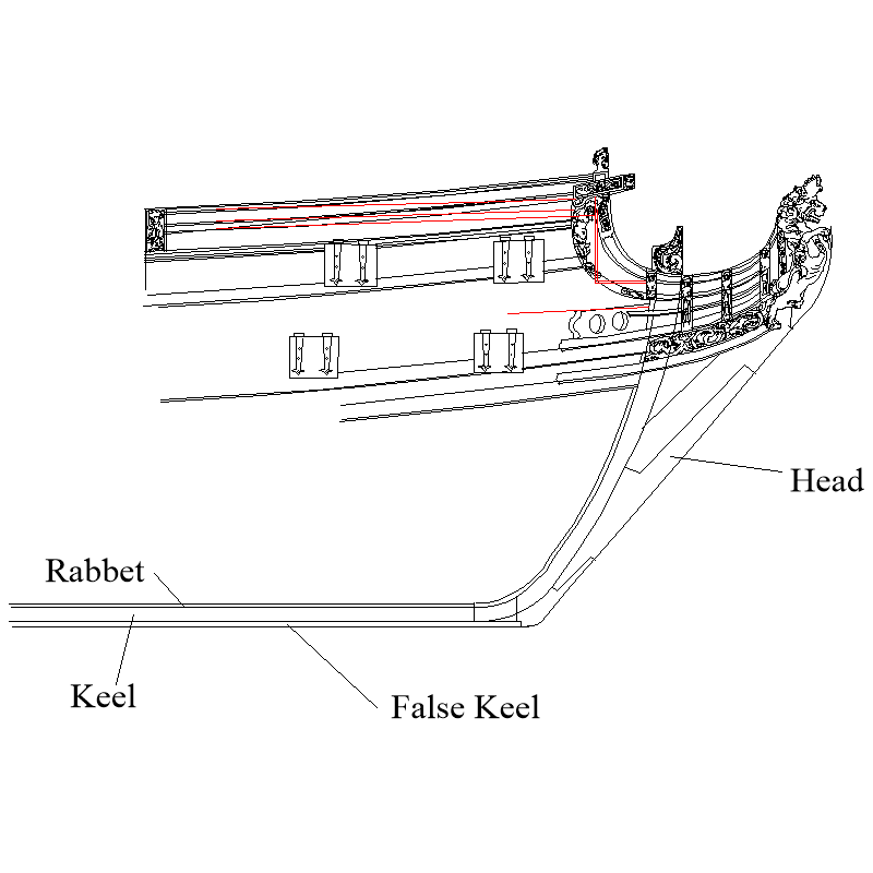
Are you speaking of the false keel which is the thin (6" for a 36 gun) strip attached to the underside of the keel or the keel itself? If the keel itself, based on the Shipbuilder's Repository 1788 for a 36 gun British ship it was 1'3" square at midships and tapered to be sided at the stem and stern post 1' 0" This tapering may expose layers of the plywood. The tapering of the stern post and head are even more pronounced so there will surely be one, maybe two layers of plywood exposed which is not a great look. Other than for the bulkheads, you may want to consider using solid material rather than plywood for these various pieces if you are going to shape them for a more realistic look. The tapering of the head is shown in the following build log. It is a different ship, but same idea applies. https://modelshipworld.com/topic/33157-rattlesnake-by-ed-ku20-model-shipways-164/page/3/#comment-978894 Allan
-
What you say makes a lot of sense. As a scratcher, I love my power tools, but there was no electricity when those gorgeous models of the 17th and 18th centuries were built so we know it can be done without the power. Allan
-
1/48 3 ball with capping rail stanchions
allanyed replied to Richard Dunn's topic in Metal Work, Soldering and Metal Fittings
There was a post on the same thing with several good replies a couple weeks ago. You should be able find the string with the search tool or someone might remember where it was and add a link for you. Allan -
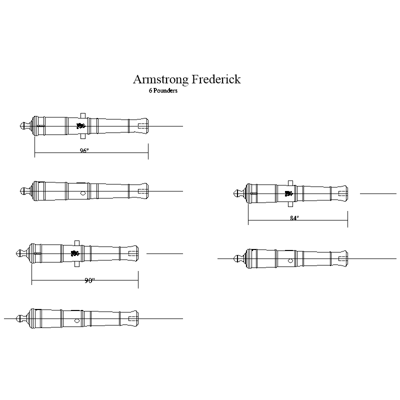
For the future...... We are working on drawings of cannon from the 17th century through the age of the Blomefields, including STL drawings that can be emailed to a 3D printer firm to have them made of black resin (or brass colored for the older brass barrels) I have had them made for as little as 60 cents each. Fly would have most likely had 6 pounder Armstrong Frederick guns, The 2D can be seen below. The 3D are also below. To open the 3D is not needed, just send them to the printer with the length that you want. If anyone wants to open the 3D, download, for free, either Fusion 360 or Blender or similar program. These drawings have the cascabel ring, the correct number of reinforce rings and the George II cipher for that era based on drawings from The History of English Sea Ordnance by Adrian Caruana. I have also attached PDFs which are more clear than the pngs below. Keep in mind the lengths given for cannon are from the muzzle to the breeching ring, not the end of the cascabel. The overall length is to the end of the cascabel. The following chart is for the 6 pounder AFs. 7 foot - Overall length at 1:64 1.5" (38.1mm) 7 foot 6 inches- Overall length at 1:64 1.6" (40.78mm) 8 foot - Overall length at 1:64 1.69" (42.8mm) Just as an FYI, as I do not have a 3D printer I used an outside commerical printer. I have not paid more than $0.60 each, including freight within the US for similar size barrels and the quality was excellent. I am sure it would be similar in most countries. Allan 6-84.stl 6-90.stl 6-96.stl 6 pounders.PDF
-
Scroll saw versus band saw
allanyed replied to Juddson's topic in Modeling tools and Workshop Equipment
I cannot speak for others, but this has never been a problem for me. I have cut two sets of castello frames (about 1000 pieces for the floors, futtocks and top timbers) for a 1:48 and a 1:64 hull with my DW788 saw without any issues whatsoever. I did break two blades in the process but that is a two minute fix for a couple dollars. For slitting billets, I found that a band saw is the best way to go as it works well and makes for less sawdust than a table saw. When I find the need I just borrow the one I sold to the guy down the street. 😀 Allan -
Scroll saw versus band saw
allanyed replied to Juddson's topic in Modeling tools and Workshop Equipment
Based on scales smaller than 1/12 I totally agree. The ideal situation is to have both I suppose if you have the needs. I have had both and finally sold the band saw to a neighbor that does carpentry work when I realized I rarely used it. I then replaced my old scroll saw which had the shakes with a new Dewalt and could not be happier. Some stores in the US s offer 10% discounts to military vets so don't forget to ask. Allan -
He Jeff Your are not alone. Not only did I do the same thing, I did it scratch as I could only afford the plans, not the kit. In the end it came out well enough that I actually sold it for a reasonable price. Stick with it and it will come out fine. If you do not have it, get a copy of The Anatomy of Nelson's Ships by Longridge as it has a WEALTH of information on building a model of the Victory and will help you immensely. Allan
-
Your building is going great, but most of the photos are upside down and it is nauseating to keep standing on our heads to see what you have been doing. PLEASE do an edit, delete them and re-paste right side up. I think more people will stay tuned. Thanks Allan
-
Take this comment from Bob seriously. It should be in a case in a room with a northern exposure or even better. a windowless room with no chance of direct sunlight. Allan
-
In a word, yes it does get wider as you move downward. Picture and a thousand words, &c. It is based on a drawing in Volume I of TFFM by David Antscherl. The dimensions shown are from Steel's Elements and Practice of Naval Architecture for a British 24. Allan

-
Plastic or Wood models? Your Favorite?
allanyed replied to Bill97's topic in Modeling tools and Workshop Equipment
I second, third, fourth this suggestion strongly. Allan -
Your work looks super B.E.👍 You might consider temporarily adding the garboard strake and then recheck the marks for the ends/widths of the planks. The main thing about the garboard is to be sure it does not run past the boxing joint of the keel and stem which looks to be between the second and third forward most bulkheads. Allan
- 648 replies
-
- 3
-

-
- Indefatigable
- Vanguard Models
- (and 1 more)
-
There are a LOT that would help, but get them as you need them. I would add a scalpel with packages of a few different blades. As with most things you get what you pay for even for this kind of little thing. You can't go wrong with Swann Morton handles and blades. Xacto brand blades and holders are an OK substitute for the scalpel, but they use round holders which will roll. Remember that if it rolls off the work surface it will always fall blade down when heading towards your leg or foot. (I think that is an international law 😀. ) You will need a decent measuring instrument so you might want to get at least a good quality steel rule or better, a digital caliper. Good luck and welcome to the dark hole of scratch building. Allan
-
The joinery and overall precision in your builds yields a true work of art. Allan
-
Hi Bruce The 4 pounder long barrel looks like an Armstrong-Frederick pattern with the telltale ring around the button of the cascabel. Nice find! Allan
- 1 reply
-
- 2
-
