DONATION DRIVE - SUPPORT MSW - DO YOUR PART TO KEEP THIS GREAT FORUM GOING!
×


allanyed
-
Posts
8,149 -
Joined
-
Last visited
Content Type
Profiles
Forums
Gallery
Events
Everything posted by allanyed
-
Hi Grant, Sorry, but I doubt the information from Lees will be worthwhile. Hope you find some contemporary based data. There are rope sizes but not chain sizes. Looking at equivalents on line, it SEEMS chain with links made of material 1/2 the diameter of the rope diameter would be appropriate. This does not necessarily give the link width or length though. I hope someone has the data as it will be interesting to see how rope and chain compare in this case. Does the topic or the book on Ed Tosti's Young America build go into this? Allan
-
If I had room I would take a drive over there as the price is certainly very attractive, but hard to tell from the photo what kind of shape it is in, They do not provide provenance, authenticity or quality. Allan
-
 I am not kidding, I am looking for an answer on this one. It is part of the caulking description in a 1776 contract for a British sixth rate The entire phrase (the spelling is as in the contract) is The white ocham to be from flying & not from ground toes or decaid White ropes. A part of the original is below. TIA Allan
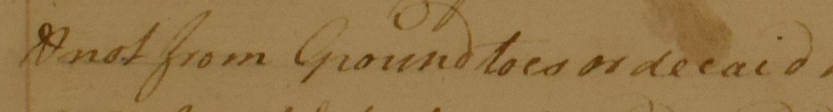
-
Hi Grant What nation/ship/era? James Lees goes into describing chain slings and truss pendants and falls on the lower yards for British war ships after about 1850 but these may not be appropriate for your ship. Allan
-
From the website it does not appear that he makes internally stropped blocks which is what Bill would require for his late 19th century fishing schooner. Do you know if Radek also has internally stropped blocks? Thanks Allan
-
Looking forward to seeing your work on a build log one day soon Pam. Again, warm welcome to MSW Allan
-
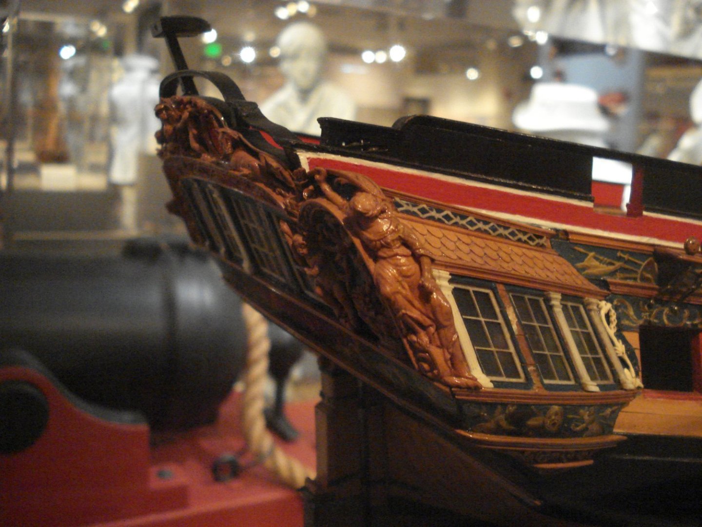
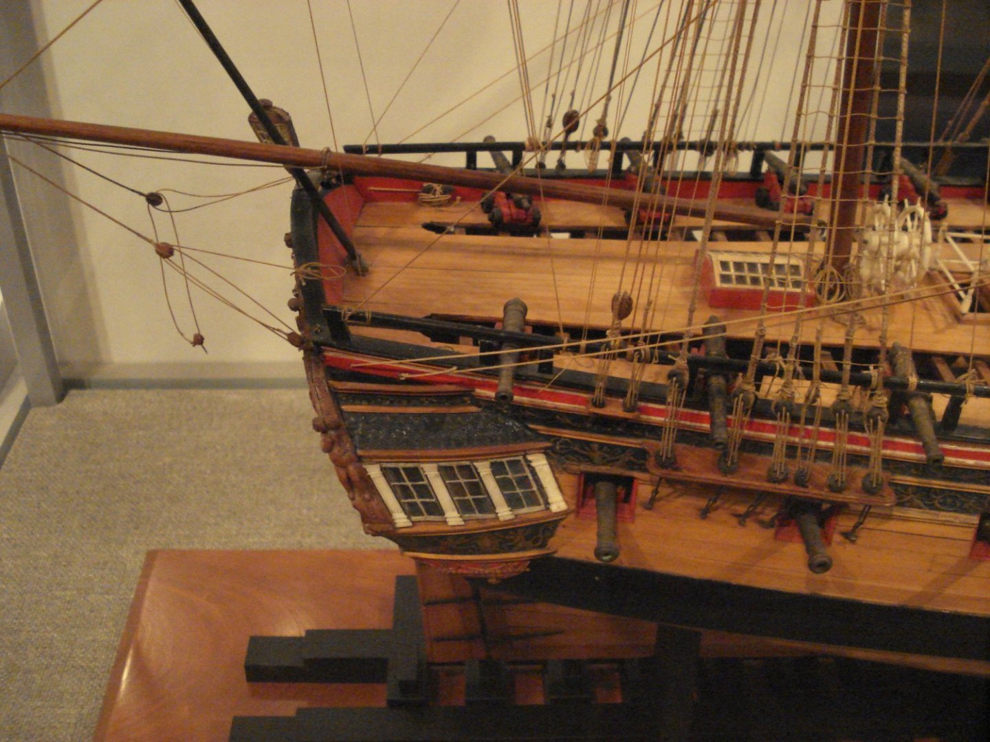
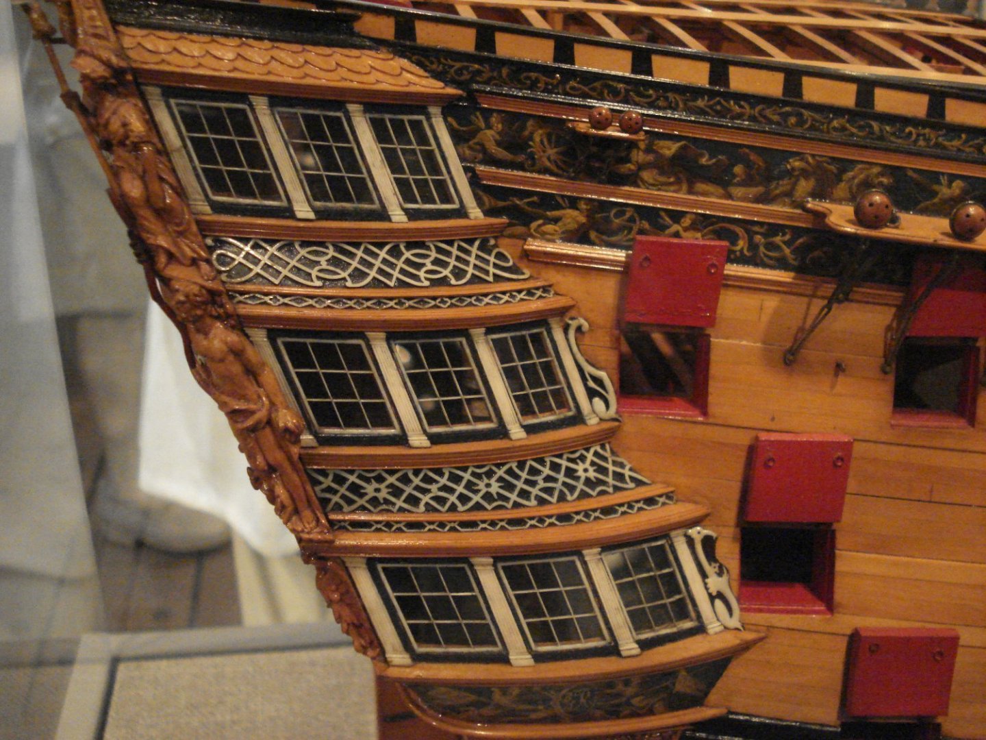
Depends on the nation, era, size, yard &c. There are hundreds of photos of contemporary models on the RMG Collections web site that you can see and get some ideas. The first photo below is a contemporary model of a 5th rate at Preble Hall & shows a bit of detail. Couple others from Preble follow as well. If you do a search at RMG you can see the Lowestoft, 20, (1723) It appears to have some sort of simple deco. Other contemporary models have no decoration in that location. Allan
-
Assuming your vessel is from before the use of copper sheathing and it would have a bottom coated with white stuff this has been discussed here at MSW and may be a little help for you. One such thread is at https://modelshipworld.com/topic/2798-hull-white-stuff-on-17th-century-ship/ I doubt that there is one exact "right white" color but unbleached titanium dioxide mixed with a little yellow ochre and/or burnt umber should work. Other members may have more details for you. In the end, the paints were not made in a factory like PPG or Sherwin Williams with color standards to be met for every batch for every ship so the color could have varied a little from ship to ship. Hopefully someone has more details for you. Allan
-
Not knowing your current name, I'll go with your former, so... Hi Pat 😀 Warm welcome to MSW. I wish I had such a group (and the internet) when I was in torment during the early stages of learning ship modeling. Consider yourself a very lucky guy/gal. Allan
-
Sort of like a long lost friend that returns home after being gone for too long and everyone, including me, is very happy you are back. Allan
-
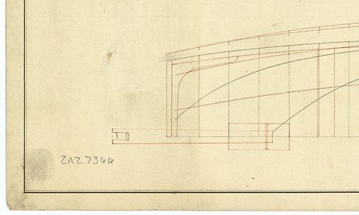
The below may help although it does not show the side supports. I have seen contemporary drawings that show them and others that do not. Why the kit would have something so thin is odd as the other items in the kit seems to be done so well. Perhaps there were two pieces that were supposed to be sandwiched together with the sheave between??? IF you are mounting the launch on the ship, the davit would not be in place so removing it may be an alternative way to go. Allan
-
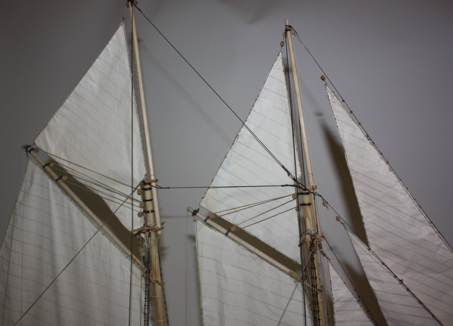
Internally stropped blocks are likely the most appropriate. There are drawings and detailed list of block sizes for several fishing schooners including Grampus 1885, and Columbia in Chapelle's American Fishing Schooners Pages 341-347, not to mention a LOT of other details on construction, rigging, et al. One example on a model follows, it being Ernestina 1894 Allan

-
Bill Did you read the new post from Syren re: blocks that was posted by Chuck Passaro the other day? https://modelshipworld.com/topic/33948-syren-ship-model-company-news-updates-and-infopart-2/page/4/#comments post number 95 on page 4. Look at those blocks and compare to those that you have from MS. Night and day if a realistic looking block is important to you. Allan
-
Lovely build! One question/comment, hope that is OK, The davit for working the ship's anchors looks thin. Looking at contemporary launch drawings they were typically 7.5 to 8 inches wide (3mm at your scale), had a roller at the outboard end, and were supported on the sides by the runners so would be nearly touching them. From the photos the one in the model looks closer to 1mm. I hope this is not coming across as picky but it sort of jumped out for me from a functionality point. Allan
-
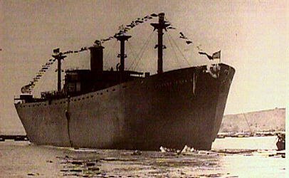
Every time I see a Liberty Ship project it reminds of Edwin O'Hara, one of 142 cadets from the US Merchant Marine Academy killed while sailing as cadets during WWII. They are the only cadets from any US Federal academy that were killed while sailing as cadets during the war. The story of O'Hara is worth reading. https://thewildgeese.irish/profiles/blogs/wwii-hero-edwin-o-hara-the-honor-but-not-the-medal I vividly remember the painting in the article hanging in O'Hara Hall at the USMMA. Photo of O'Hara's ship, the SS Stephen Hopkins is below. Acta Non Verba Allan
- 54 replies
-
- 4
-

-
- Liberty Ship
- Finished
- (and 2 more)
-
Tiziano, I am very impressed that you only made one extra spoke on each set. I tend to make several knowing I will lose at least one under the work bench and/or break one along the way.😀😀 Are you using a mill or some other unit to mill the grooves? I don't remember if you and I discussed this when we met last year but for those without a mill, a mini table drill press to route out the grooves when making these parts can be used. It is not really a recommended use of a press due to the types of bearings, but it worked out very well. Allan Allan
-
Let me be the first to offer you a very warm welcome to MSW Herby. (Hope it is OK to call you Herby) Allan
-
Funny😀😀 Actually I wish I could enjoy the idea of wabi sabi as much as enjoy fresh wasabi. Hint,,,, if you ever get too much of a hit of wasabi and your brain is going to explode, a quick spoonful of miso soup will kill the hot sting. Learned the hard way from a Japanese master sushi chef in Manhattan many years ago!!! Allan
-
French 1/1 mainmast stay rope 1680-1700, La Belle 1680
allanyed replied to Kuba91nt's topic in Masting, rigging and sails
Going off topic here and you may be right but the symbol looks like a Rasta lion and I THINK Kuba is not an uncommon Rastafarian name. Allan -
Bill You do not mention what ship and era. Do you need internally stropped or externally stropped? There are more options with externally stropped but in either case if you really want beautiful blocks, get them from Syren. They make other after market blocks look totally amateurish not to mention unrealistic which they are. Allan
-
VERY nice start. I am on for the entire trip. Mark, please be ready to share the popcorn. Allan
-
By far one of the finest looking ship's boats here at MSW Beautiful work Craig. Allan
-
HMS Granado by ir3 - CAF - 1:48 - POF
allanyed replied to ir3's topic in - Kit build logs for subjects built from 1501 - 1750
Framing is very well done IR3 How deep are the scores in the clamps? When they were scored (and this was not always done according to Goodwin in The Construction and Fitting of the English Man of War) it was only an inch, so at your scale 0.02" I have found it difficult to do this before installing them and get them to perfectly align port and starboard so if I score them it has been easier for me to do this after they are fixed in place. Using pre-scored clamps, I hope yours are easier to align than I have experienced. Allan -
Unfortunately I have propagated the problem Druxey as I used the same exact figures in the Scantlings of the Royal Navy when compiling the various sources of scantlings for the book and at this point I am not sure how to provide the corrections. Allan .
-
Tiller tackle
allanyed replied to Dr PR's topic in Discussion for a Ship's Deck Furniture, Guns, boats and other Fittings
Totally agreed. There is a TON of information from contemporary plans, contracts, and text from the 17th century on and it gets better into the 18th an 19th centuries, but in the words of Gilda Radner, It's Always Something and these little things take longer than many of the bigger things to figure out. I just found discrepancies this morning in the Simm Comfort edition of The Elements and Practices of Naval Architecture scantlings by David Steel that would make for very obvious possible mistakes on deck for some larger vessels regarding the heights of the coamings and head ledges. Allan