allanyed
-
Posts
8,149 -
Joined
-
Last visited
Content Type
Profiles
Forums
Gallery
Events
Everything posted by allanyed
-
 Your model is extremely well done and it does bring up a question. There are scantlings for the size of the floors and futtocks of many types of boats, but I have yet to find the space between frames provided anywhere except for about 1705. From W.E. Mays book page 54, for a 21 foot to 24 foot yawl, the distance between frames was typically 11" (1.1" at 1:10 scale) The range for various boats that he gives in this time period is 10.5 inches to 12 inches, so I have used these for later periods, not having having better information. I would love to find these dimensions based on contemporary information for later period boats. Allan
 -
Like hull planking, it is easy to shape the planks using the method Chuck Passaro describes in his four part video that has been posted here at MSW and can be Googled. That, or spile the planks as has been done on both ships and models. Hope you give it a try in the future and like the results. Allan
-
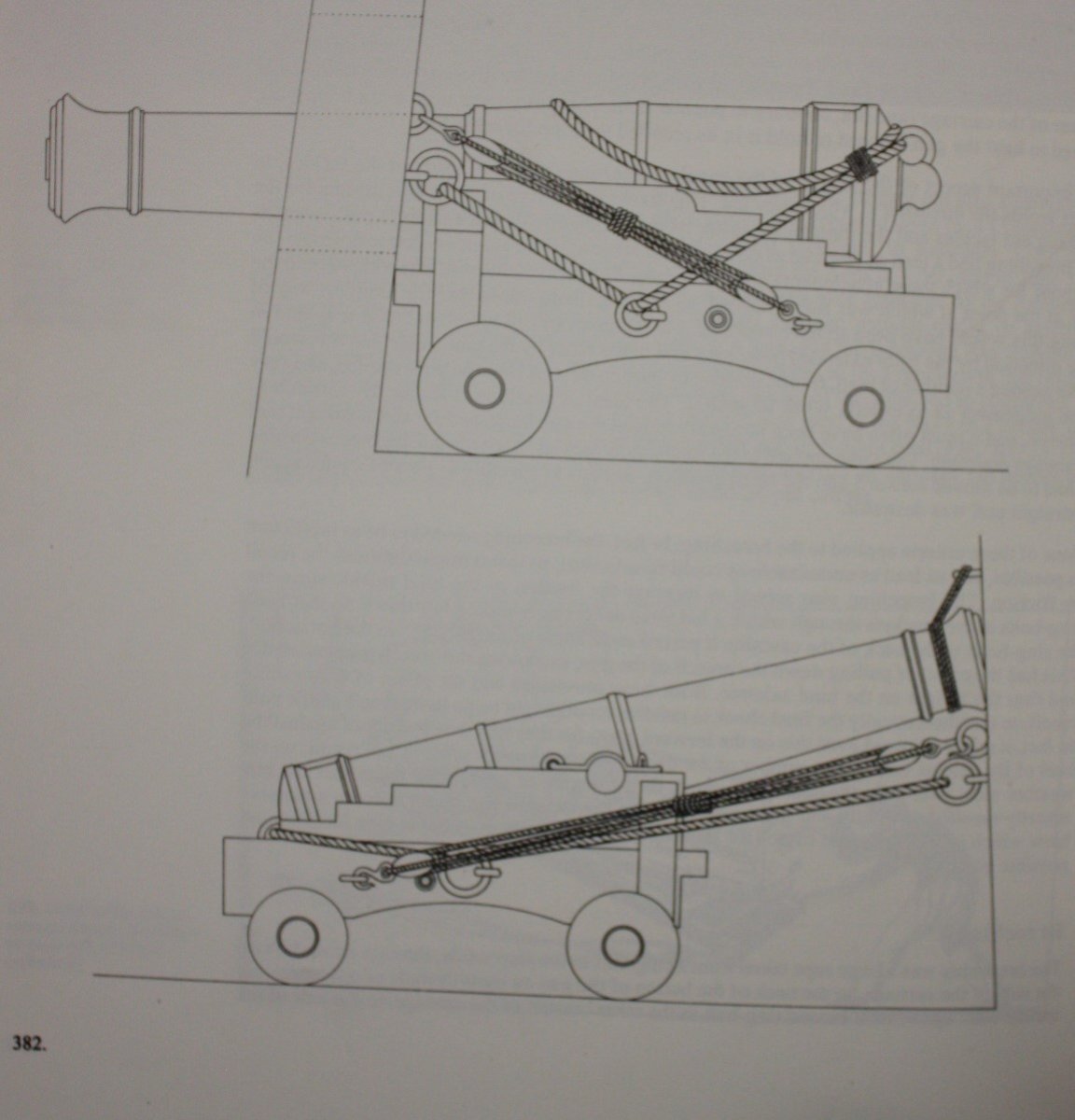
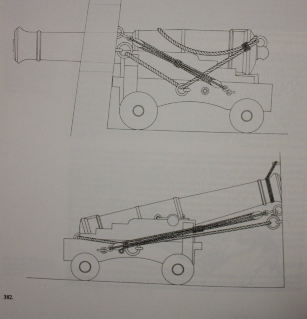
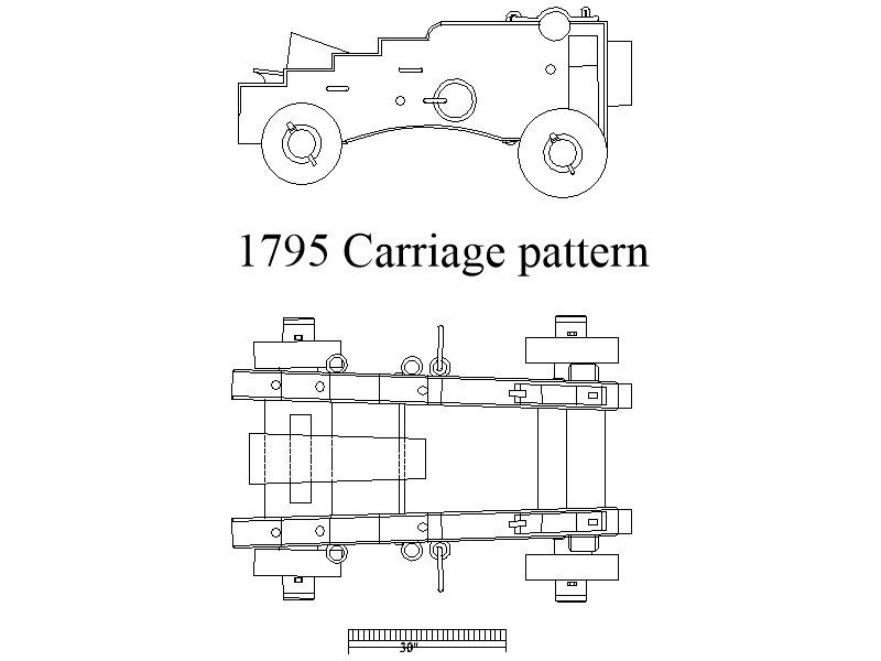
Hi Gregory, I think you are right about this. Caruana shows single rings on older carriage cheeks and doubles on later cheeks, but that is not to say he was infallible and may have made a mistake. In this case, he shows the cleats on the sides and front indicating a later carriage which leads me to believe there should be two rings on each side. Still would love to know what the second one was use for. Never saw this on any drawing based on contemporary sources. I have never seen the train tackle set up like the painting shows. Artist's license??? 😁 There are rings for this on the cheeks, but not used. Caruana only mentions the use of a double and a single for 32 pounders and two singles for all others. He makes no mention of 42 pounders so MAYBE the triple was appropriate. Who knows on any individual ship without a trip on the proverbial Waback machine?? Allan
-
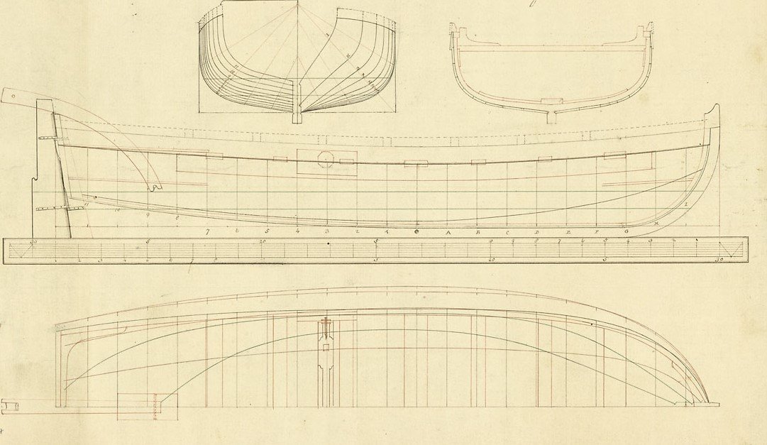
I thought that might be the situation. See below plan for plank breadth and thickness for a launch of 1779. The breadth on this and several other contemporary drawings that I looked at were what would be between 2.8 and 3.5mm wide at 1:64 scale. Scantlings in W.E. Mays book on boats for a 24 foot launch is 7/8" but I would go thicker like you did so there is material to work with for scraping or sanding. The wider stakes might make the planking a bit easier for the next project. Still, kudos on your planking at this scale which looks very well done. Allan
-
Hi Nipper I initially thought this might be the case, but now think this is not the reason for the ring based on the below from Caruana, Volume 2 Allan
-
Super planking on such a small scale! Do you know the width and thickness of the planking that was provided? Thanks Allan
-
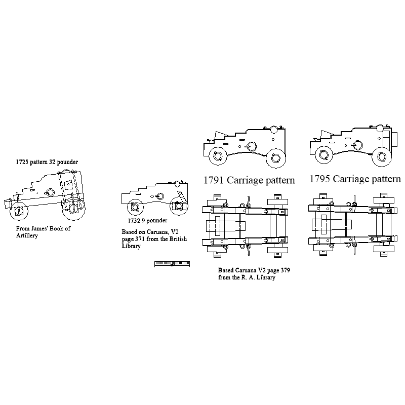
Some patterns of gun carriages show two eye bolts without rings on each cheek, others only one. What is the purpose of the additional ring? I cannot find any rigged guns where the second ring is used. Note that Caruana shows some cheeks with two fixed rings on some larger 1732 patterns. See below Allan
-
Hi David, Did you look at the contemporary model of Diana at RMG https://www.rmg.co.uk/collections/objects/rmgc-object-66303 or the high resolution RMG plans on the Wiki Commons site (https://commons.wikimedia.org/wiki/Category:Ship_plans_of_the_Royal_Museums_Greenwich page 4) that includes Artois 1794, Diana 1794 and others of the Artois class? Comparing these to your kit may give you some help. Allan
-
Welcome aboard. I have fond memories of some fantastic striped bass fishing in the narrows near the VN bridge. Allan
-
I am, PMing them to you along with a 3D printer service that I have used in the past should you need one. Allan
-
ABSOUTELY a classic photo. Looks like a Springer or liver colored Brittany giving you the eye. LOVE those breeds. Allan
- 443 replies
-
- 6
-

-
- Indefatigable
- Vanguard Models
- (and 1 more)
-
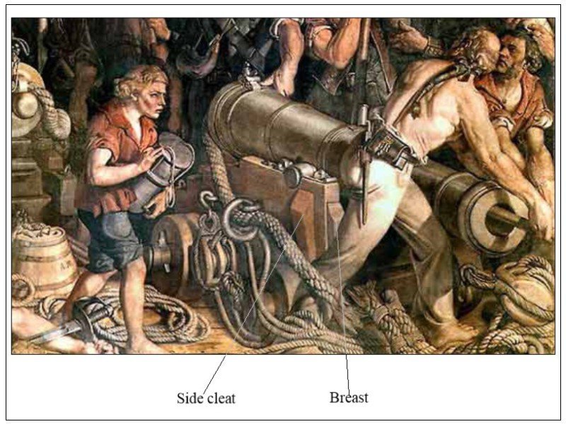
Hi Ron Will you be adding the cleats to the carriage cheeks? I am not sure if they were on all size gun carriages but they do show up in contemporary paintings of Victory as well as on the drawings in Caruana. I doubt many people would notice, so maybe better to leave them as they are. Just a thought. Just in case, you can see these on the painting as well as the drawing from Congreve and also redrawn in Caruana.
-
Chris You are fortunate to have a better equipped shop than 99% of the members here, including some of those that are master builders. But to paraphrase some of the words of Tim "the tool man" Taylor, you can never have too much power or too many tools. Allan
-
Hi Chris Including both ship modeling as well as the "other non ship building purposes" what specifically do you plan to use the saw for? Allan
-
I will be interested to see if anyone posts sources for accurate boats. I have looked for well made ships' boats for many years without luck but perhaps they now exist. Scratch building them are fun little projects that will hone your skills and can be done with simple hand tools. Appropriate boats would be from the first quarter of the 19th century assuming the Pequod was based on the real whaler Essex. Hopefully the following will be of some help to you if you are relegated to scratch building them. https://www.rmg.co.uk/collections/objects/rmgc-object-460842 https://www.rmg.co.uk/stories/blog/nineteenth-century-whaleboats-commercial-technology-naval-craft Allan
-
WV, Welcome to MSW!! If you follow the recommendations in posts #2, #3, and #4 above you will be happy. The designer of these three models is a professional model builder and author on ship modeling with a lifetime of experience helping beginners and masters alike and he is a member here. He can lend advice if you post a build log of your work and run into issues or have questions during your build. Allan
-
Druxey I think it is a drawing of Unite 1796, a French capture prior to being converted to a 32 at Plymouth. Allan
-
Hi George, Tail draggers do seem to be very common in the 15th and 16th centuries and there definitely is a lot of good information on the Mary Rose, based on objects from the wreck site, but unfortunately they seem to have few, if any similarities, to the Browne pattern cannon (circa 1625-1649) and their carriages. Allan
-
Nicely done Glenn For the future, there are a lot of contemporary planking expansion plans on the RMG Collections site, both inboard and outboard that you may find helpful as well. One example is https://www.rmg.co.uk/collections/objects/rmgc-object-83495 Allan
- 587 replies
-
- 3
-

-
-
- Indefatigable
- Vanguard Models
- (and 1 more)
-
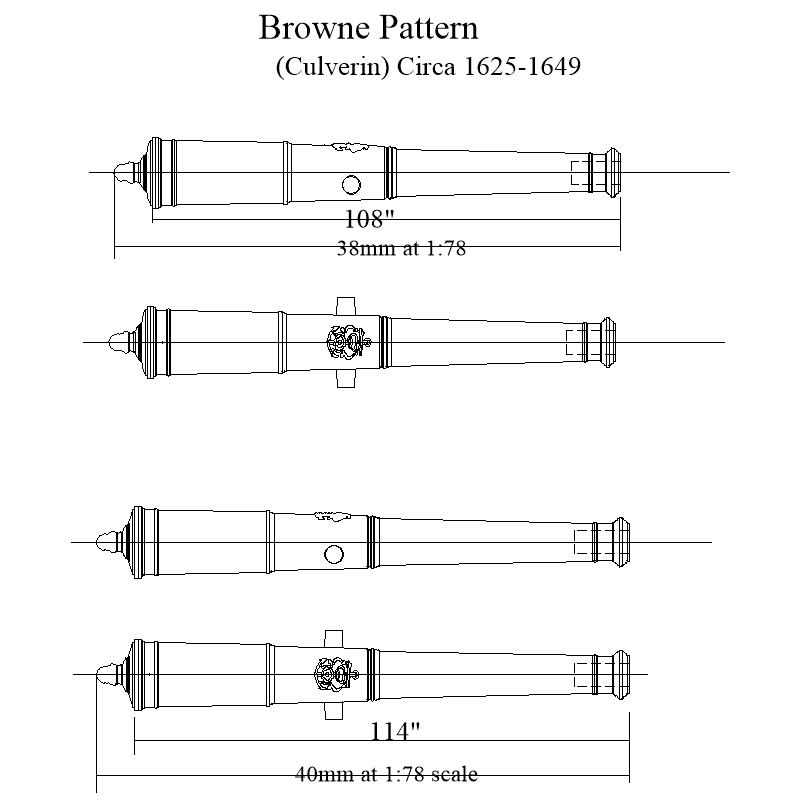
In addition to the carriages, the gun patterns do not look right. She would have carried Browne pattern barrels (circa 1625-1649) when launched. Compare the Browne pattern below, which has the badge/cypher for that time period, with the kit guns. Might be too late but I have STL drawings of the Browne Pattern in several sizes if you want them that can be sent to a 3D printer and be made in black or bronze colored resin at a really low cost. 2D drawing of one of the sizes is below as PNG and PDF Allan Culverin at 1 to 78 scale.PDF
-
Hi Ron I found out from another member that had an issue finding proper pattern barrels for his particular build that at least one supplier sells Blomefield pattern barrels that have the crest/cypher as well as the pan at the touch hole and they are relatively inexpensive. If this is of interest, please let me know. Allan
-
Maybe go to European boxwood, (buxus sempervirens)? Color is off, but I have found that is so tight grained that it is the strongest wood for small dimensioned stuff. Janka hardess of 2.840 lbf for boxwood versus 1660 for Swiss pear and 1880 for castello (calycophyllum multiforum) Allan
-
Hard to hit a well thrown curve ball Pat. 😀 Post #2 above regarding the information from Peter Goodwin only applies to 1650 to 1850 (The Construction and Fitting of the English Man of War) so your post is great information. Thanks Allan
-
Thank you Patrick. . I would like to read more. What is the publication you copied in your post? Thanks again!
- 50 replies
-
- 2
-
-
- mary rose
- caldercraft
- (and 1 more)