HOLIDAY DONATION DRIVE - SUPPORT MSW - DO YOUR PART TO KEEP THIS GREAT FORUM GOING! (Only 20 donations so far - C'mon guys!)
×


allanyed
-
Posts
8,149 -
Joined
-
Last visited
Content Type
Profiles
Forums
Gallery
Events
Everything posted by allanyed
-
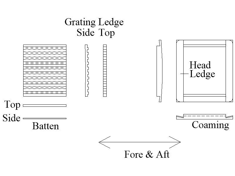
 Hi Masa Great progress!! Remember that the coamings and head ledges had specific construction as shown in post #3 above as well. They were interlocked as seen and the portion of the corners above the deck were rounded, not square. The sketch below is dimensioned for a specific ship, but the construction style is generic. Allan
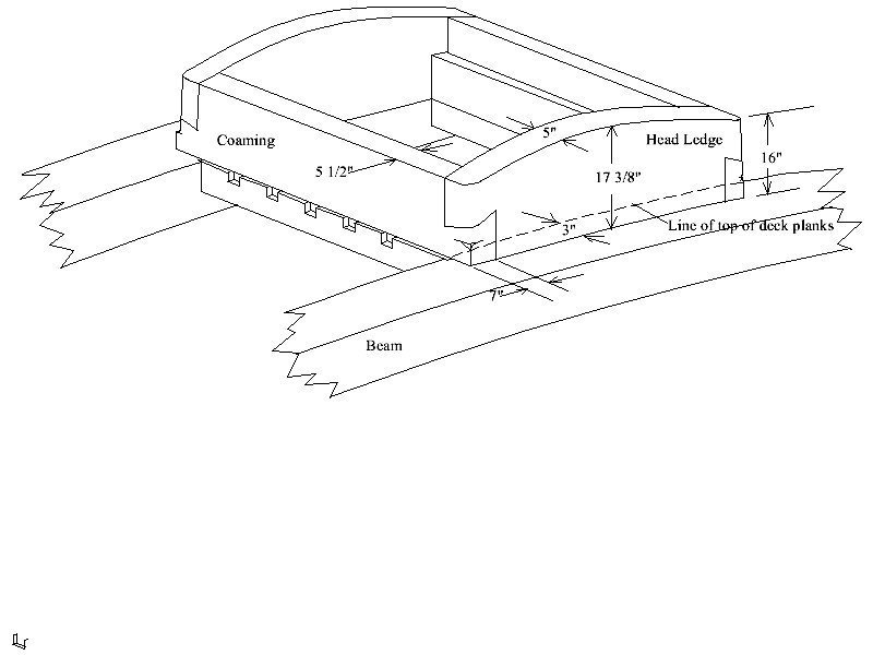
-
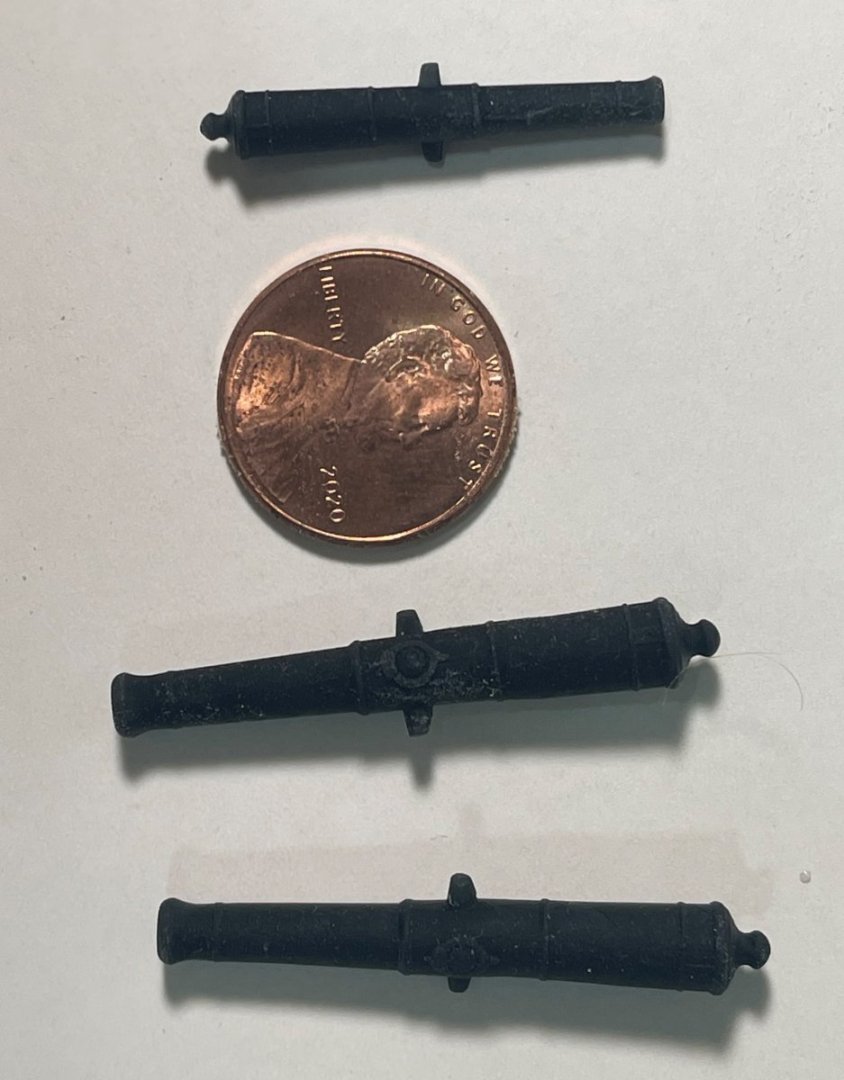
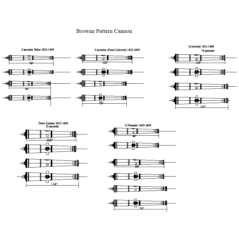
Phil, Considering all the work you did to make wooden cannons, did you consider 3D printed guns? They are cheap and extremely accurate. The earliest that several of us have drawn up are Pitt and Browne patterns from the 17th century but the Browne and even the Commonwealth pattern (below) looks similar to those that you made. 3D drawings can be sent to a 3D printer and made for about $0.60 each in any scale you want. If you wish, please feel free to PM me I and can send you STL drawings that you can send to a 3D printer. 2D drawings of Browne are below. The png pic is not so clear but open the PDF and you can compare the patterns to the ones you are using. Cannon perrier was a new one for me. As they were Portuguese, do you know how they came about to be on the Revenge? This is really interesting and I would like to hear more about these if you can share the information you have on these. Allan Browne Pattern 1625 to 1649.PDF
-
HI David, Can you post a photo or tell us the specific lines? I know of lines such as lifts and halyards that pass through a mast, going over a sheave, rather than going through a block, but am having trouble thinking of any line that goes through a hole in a mast to be belayed on the opposite side. Allan
-
Which ship? We have a number of STL drawings completed of cannon that you can send to a 3D printer and have them made in black resin. I paid about $0.60 each for perfect cannon, including freight, about a year ago. We have about 30 cannon drawings done with over a 100 to go but there might be a fit with the ones that are complete depending on which ship your building, Allan
-
David, I would bet that there are no members that don't mess up a part on a weekly or even daily basis. You are not alone. Our own responses on how we fix our own mistakes seems to be what varies. Do we make a replacement or do we try to fix it as best we can? Allan
- 218 replies
-
- 2
-

-
- Victory
- Caldercraft
- (and 1 more)
-
Nice intro Peter, warm welcome to MSW! Allan
-
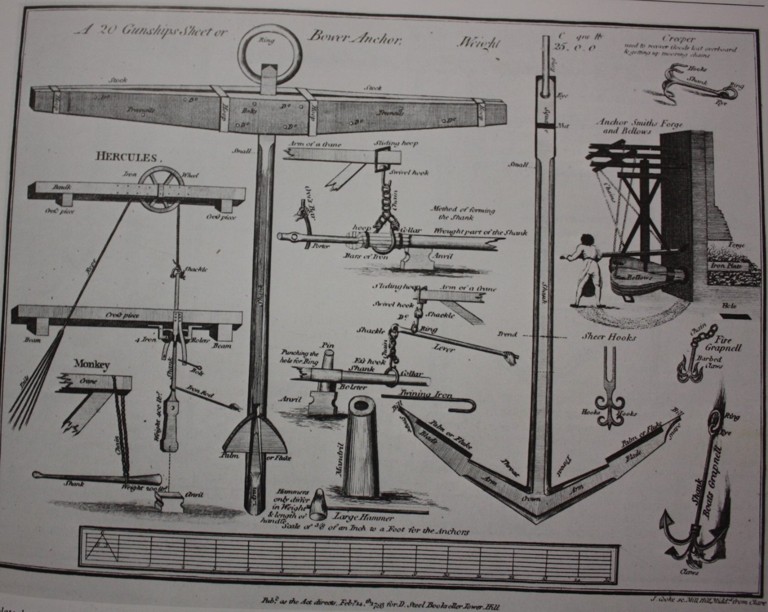
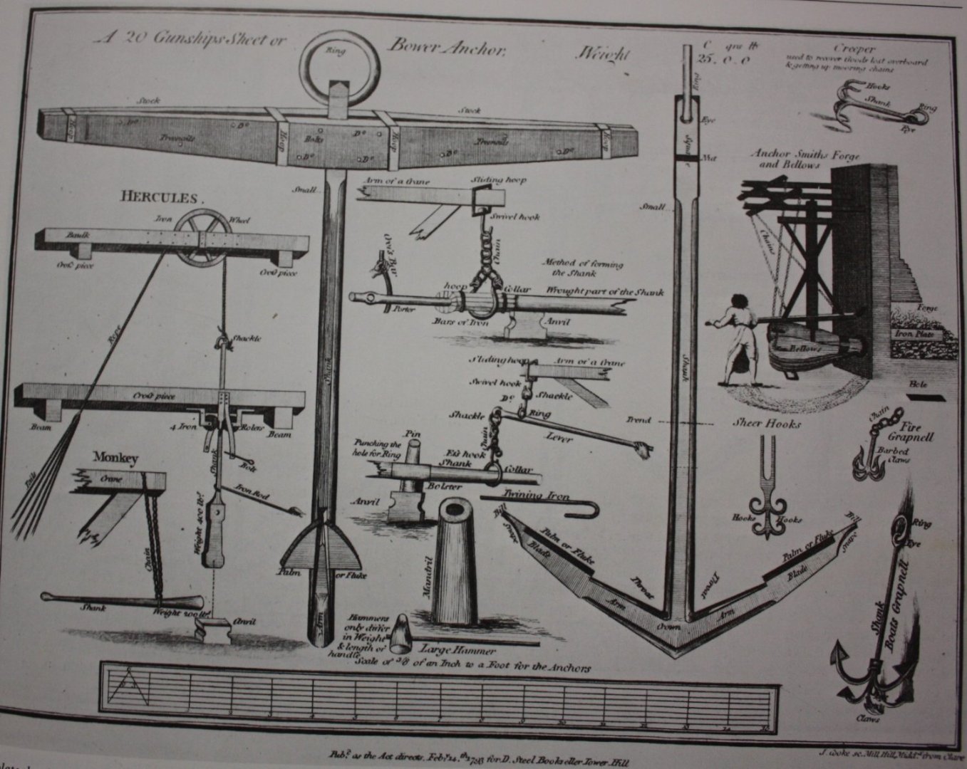
The anchors really look good. Below is a contemporary drawing from 1797 held at the Science Museum . While it is a sheet or bower anchor for a 20 gun ship, it may still be of some help in comparing to the drawings in the AOS book. Allan
- 310 replies
-
- 5
-
-
- Diana
- Caldercraft
- (and 1 more)
-
Hi B.E. You are 100% correct about the taper of the stem, apron and knee of the head moving vertically as well as horizontally and it can be tricky. Even the sided dimension of the keel tapers 3 inches on a 64 from midships to the sternpost and from midships to the stem so this would have to be accounted for as well. Same goes for the sternpost which tapers from 19.5" at the top to 14" at the keel. As you say, sometimes it may be better to forget meddling. Allan
- 648 replies
-
- 2
-
-
- Indefatigable
- Vanguard Models
- (and 1 more)
-
They would be the same as pins from what I have seen. Both sides for each thwart for a double banked boat, alternating for single banked. Allan
-
Alan, If I had a dollar for every typo or rushed response with a mistake I would be living on the beach in Wailea. Allan
-
Maybe I am missing something, but I thought lateen sails were fore and aft rigged. Regardless, if a mast passes through partners where it pierces a deck, wedges would work. Mizzen masts on contemporary models that carried a lateen have wedges. Small craft may be a different story where something like the half hoop steadies a mast against a thwart. Allan
-
Hi James I am only adding what I can find based on contemporary information rather than modern sources. I have the Pandora book and again I may be wrong but I am pretty sure the set up of the tholes in the book is wrong. Looking at the files in the Boats of Men of War book by W. E. Mays, the narrowest boat that is double banked that he shows that I could find is 7' 8". There have been good discussions on this and other items on boats from the ears to the oar lengths here at MSW that may help. I am sure there are some members that are far more learned on contemporary details for ships' boats that can add more information for you. There are contracts for boats that may also be of some help. One small part of a contemporary contract from September 9, 1790 gives the following for a yawl. I see no way there can be two rowers on a thwart that is only 5' 7 " and not be in each others' way. Yawle of Long Broad Deep 23 ft 5 7 ins 2 5 ins
-
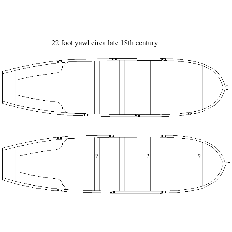
Love that you used silk span for the sails and your wood joinery is great. For the future, and I may be completely wrong, but from what I have researched in contemporary based information, a 22 foot yawl would be about 5' 9" in breadth so would have to be single banked with a thole alternating port and starboard on every other thwart rather than both a port and starboard on a single thwart then missing a thole on the alternate thwart. Leaving a thwart without a thole for an oar does not seem to make any sense, but that may just be me. Below is a sketch with what I am referring to showing single banked versus partial double banked. Allan
-
I have tried turning these in the past and the flexing is far too much to control. On the other hand I have found that an octagon or hexadecagon shaped rod can be spun on a lathe and sanded by wrapping a piece of sand paper around the piece and moving it along the length as flexing is not a concern. The masts taper from the partners downward and upward so continual checks are needed to get to the proper diameters along its length. Allan
-
Do you mean the technique that you designed? With your apparent drawing skills, why not modify your drawings to match those of actual gratings rather than something that was never used in actual practice? If that does not suit your needs do whatever makes you happy. The most obvious thing is to have the battens running fore and aft, not athwartships as Druxey has explained. Allan
-
Further to Druxey
-
If that is the case, the plans appear to be scaled at 1" = 100" A 1" long gun would be just short of a 8' 6" barrel. I am PM'g you 3D drawings of 9 and 18 pounder guns in that length that you can use to get these 3D printed in black resin. Let me know if you need contact information on a printer or you can give them to a printer close to your home to discuss. These will be FULL size drawings so you need to tell your printer you want them scaled down to 1:100. Allan
-
Hi Benjamin, At fifteen years old you may very well be our youngest ship modeler at MSW. Congratulations! I realize all this might becoming a jigsaw puzzle of sorts for you. Just take a step or two at a time and it will all come together. Let us know what size you decide to go with and I will send you the appropriate 3D drawings if I have them for the sizes you need. It may be easy to confirm the scale if you can let us know what the size of the paper plan is? If it is 1:70 scale I am guessing they are about 36" X 24" Allan
-
Benjamin, I PM'd you 32 pounder carronade drawings and as you now know, they are totally inappropriate except for the times mentioned above. If you are going to go with long guns, I can email you 3D drawings of long guns at your scale that are more appropriate in pattern. They will be Armstrong Frederick pattern, but at your scale will certainly be closer in looks than having all Carronades like those built at Carron. It matters a lot if YOU want the model to look like the ship did. If you don't care, so be it, it is your model after all. If you PM me what calibers (shot weight such as 9 pounders, 12pounders, etc.) I will send the 3D drawings for various lengths of each which you can email to a printer. If you need a printer in the US I can also email you a contact that has done cannon for me in the past. I have not had any made in over a year, but I am pretty sure he is still doing this. Allan
-
Arnold Ratlines were spaced 13 to 15 inches apart - David Lees The Masting and Rigging of British Ships of War, page 44. So for your scale it would be 0.1625" to 0.1875" (4.12mm to 4.76mm) This does not mean they can vary on a given set of shrouds within that range though. Whatever space you choose, it should be the same for every ratline on every set of shrouds on every mast of your particular model.
- 1 reply
-
- 4
-
-
We have a number of drawings in 3D, but for the carronades I only have the 2D at this point. I am PMing you the 2D drawings as DXF, PNG, and PDF and perhaps some member has already done them in 3D so you can get them printed. I am assuming yours is a kit from Model Shipways at 1:76 scale. If that is the scale, the overall barrel length should be 20mm, not 25mm for a 32 pounder. I scaled the original drawing and sending to you on the PM. For the actual 3Dprinting I have had samples done in various materials, but resin works far better than anything else that was tried. Allan

-
What ship, year, nationality? I have not paid more than $0.75 each, including freight, for perfect cannon, everyone exactly the same, done by a 3D printer that takes on small jobs like yours. I just emailed the appropriate drawings and I had them in a week or so. Allan
-
Thanks HH, I thought that might be the case. I realize it is a common problem with some kits, not your doing certainly, as they are about three times too fat if they were to scale. With a diameter at full scale of over 6.6 inches (170mm) , I cannot imagine how a sailor would ever get his hand around a pin handle that size. Allan
-
HH and/or Ross - Quick question, hope you gentlemen don't mind. Regarding the belaying pins what is the maximum diameter of the handle and the diameter of the pin portion? Thank you very much. Allan
-
I THINK the blackening has more to do with the ratio of the copper/zinc content of the brass you are using, not the hardness. Hopefully someone, somewhere, will find the formula used in the old standby Blacken It so we can make it ourselves if need be. Allan