
chris watton
-
Posts
2,335 -
Joined
-
Last visited
Content Type
Profiles
Forums
Gallery
Events
Everything posted by chris watton
-
 Thanks for the comments, Chris, always appreciated. I do know that if I am to design such kits, they will need a 'USP', as I have no intention of treading (very) old ground, and any new 100 foot-ish brig would need to be special. Still not made my mind up about what to do after Duchess...
 -
My experience with model carronades isn't good. They are either simple turned brass parts, always in the wrong size, or very shoddy mismatched white metal, bordering on scrap
-
I know what you mean. I have designed three sizes of carronade barrel, which hopefully will make them painless to make. The problem is that it seems that most brigs and brig-sloops/ship rigged-sloops had carronade main armament from the mid 1790's onwards. There is no getting around this. Plus they would all have been coppered below the waterline.
-
Thank you Ernie, and sorry to read about your father in law. There will be quite a lull after the Duchess of Kingston, as I will need to work out what to do next. There are still a couple of larger (95-108 foot) brigs I would like to do, but am wary about developing too much of the same type. There are two I have in mind that have main armaments of 16x32 and 16x24 pounder carronades and 2x6 pounder chase guns respectively, and another that has a main battery of 18 x 9 pounder carriage guns (and hull lines to die for) . What do you guys think? I would like to develop a frigate next - although this will take a lot longer to develop and new machinery may be required: I am considering getting another laser machine next year, a more powerful laser for the thicker ply and MDF keel and bulkhead sheets that the much larger kits will have. This would be a big investment, but feel I need a second, more powerful laser machine, especially for the size of future kits I intend to do.
-
Thank you! I will email WorldPay and ask them why you had a problem, they are usually very good. Nothing much to update right now. I have commissioned three sizes of carronade to me done for me, for future kits and separate fittings. I am currently working on PE sets for each size of cannon and carronade, as I have the cannon barrels being cast for me not and will be delivered next month. So I will be able to offer the carriage, PE detail (eyebolts etc.) and cast black resin barrels from 4-32-pounder sizes (64th only) The royal yacht is still on target for an October/early November release. There will be no hold ups for any materials as I already have everything for the kit with me (apart from print work, which cannot be done until manual and prototype model is complete). I start cutting the production parts for this next week. I think I will do a few more sizes of ships boats after the yacht, plus ships stoves, as I shall need them for future designs anyway.
-
The cannon are so small that it won't matter too much if the deck is a little higher than it should be, they should still protrude thorough the gun ports just fine.
-
Thanks, Rob. The chimney was a late addition. I realised that for future kits that have the binnacle, I needed to include the chimney, so I gave a CNC company my drawings and had them turned. I will see what we can do to make it more clear where the instructions are on the website. Diana will always have a special place for me, it was the very first period ship kit I designed, almost half a lifetime ago...
-
Hi Rob, fantastic work on the Ethalion, love it! There are instructions for the binnacle, there is a PDF file on the binnacle product page. I think!
-
You honestly do not need any of those clamps at the deck edges, as once they're in place, they can't move because they are slotted in place beyond the bulkhead tab edges. I designed it this way precisely because you wouldn't need any pins or clamps at the deck edges. All you need is a couple of pins perhaps holding the centreline of the deck flush with the top edges of the deck beams.
- 164 replies
-
- 7
-

-
- vanguard models
- flirt
- (and 1 more)
-
Sorry to read this. If you had contacted me, I am sure I could have helped with any parts you wanted to replace, including different materials. As you didn't, I couldn't...
- 1,144 replies
-
- 2
-
-
- snake
- caldercraft
- (and 1 more)
-
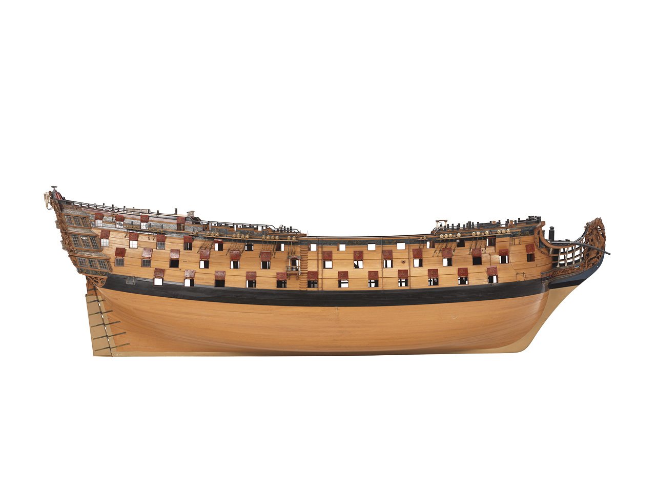
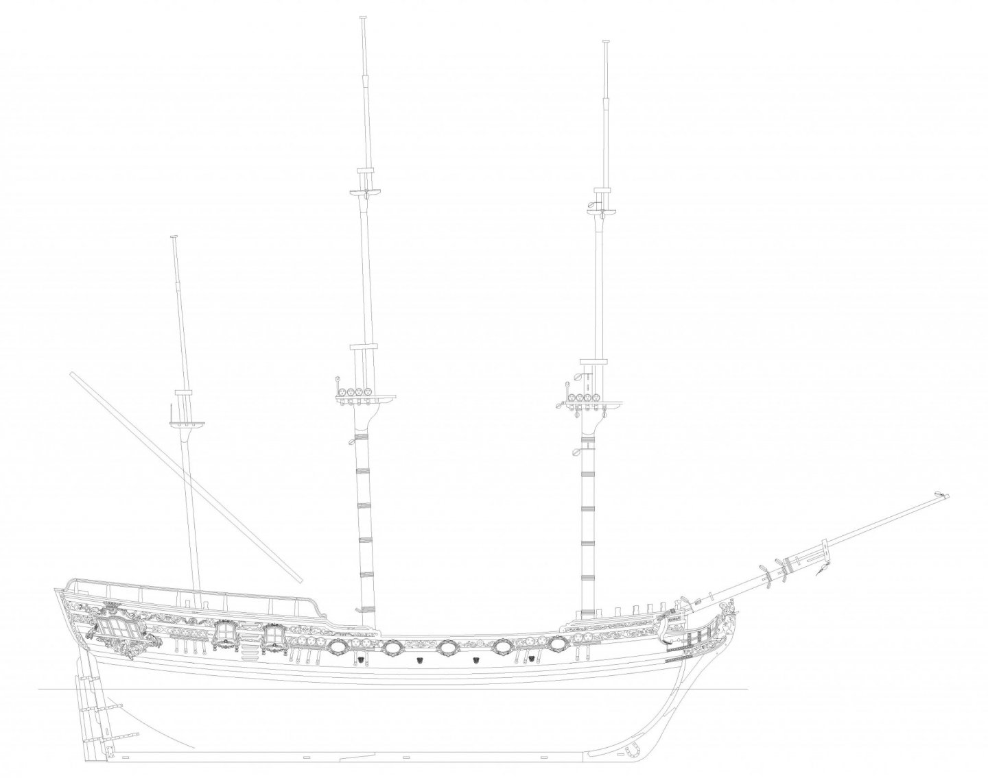
Ship rig, three masts. Have attached a VERY early mock up drawing, so you can see mast disposition
- 117 replies
-
- 21
-
-
- vanguard models
- yacht
- (and 2 more)
-
Hope so..... Otherwise all the drawings I'm currently doing will be for nothing...
- 117 replies
-
- 8
-
-
- vanguard models
- yacht
- (and 2 more)
-
I already have all production photo etched parts with me, and resin castings for stern decoration, figurehead, winch and other castings are on their way to me. All materials are with me, but will wait until I am sure all fits as it should before starting production laser cut parts. A November release is anticipated. I can tell you that designing the photo etched decoration took an absolute age...
- 117 replies
-
- 15
-
-
- vanguard models
- yacht
- (and 2 more)
-
I am forced to agree.....
-
Very pleased to read that UPS make good on their delivery times! Am sure I have mentioned this before, but I do include all blocks needed to rig the cannon for Flirt. The 'Standard' (pearwood) has 2mm single blocks and the Master Shipwright has the pearwood 2.5mm 2 hole blocks. I am aiming for a November release for the royal yacht, all going well, and if my mental acuity holds up. After this, I aim to consolidate my fittings range. For example, offer full cannon kits with barrels and PE as well as the laser cut parts. All sizes of barrel are being cast for me right now. I will also offer more PE fittings like deadeye strops, rigging hooks, and maybe offer the hand pumps as separate fittings. I will need to design a new ships Stove for my next (much larger) kit, so this should be available as a separate fitting too. But right now, I am slowly doing the drawings for plan sheets for the royal yacht - always forget just how long these take, they are a real time sink....
-
Thank you, I hope you like it. It is a world away from my Jalouse designs - but that was over two decades ago.. Tomorrow I will be receiving a huge order of pearwood blocks and deadeyes, to finally replenish stock, and once again have pearwood block and deadeye options for Alert, Speedy and standard Flirt.
-
Sometimes, I actually start the rigging lines at the belaying points and work backwards to where the rigging line starts.
-
All UPS shipping for pre-order Flirts done. According to UPS, all US customers should receive by end of day Thursday, and for the UK, tomorrow.
-
It is Vallejo Liquid Gold. I do like the Vallejo paints, as they dry very quickly. I spray the PE and resin decoration in white primer first, and then brush painted the Vallejo gold onto the parts.
-
Cheers for the links OK, All Flirt stuff is now with me, plans, manuals, box labels and shipping sleeves, so all Flirts will be shipped over the next couple of days, It is no longer pre-order, as they are now in stock. I have another large pear block and deadeye order arriving from Master-Korabel very soon, so pear block sets will be an option for standard Flirts soon (also Speedy and Alert)
-
kit review 1:32 Fifie – The Scottish Motor Fishing Vessel by Amati
chris watton replied to James H's topic in REVIEWS: Model kits
Hello Roger, I designed this particular Fifie, and I honestly do not know what else to tell you other than I used a set of plans drawn and researched by people more expert than me for this type of vessel. I remember during my own research (this was well over a decade ago now), wheelhouses were very 'ad-hock', with no two vessels being the same. These were usually old sailing vessels that were converted to screw propulsion, the Fifie type being popular for conversion due to its lack of rake at the stern and generous beam. Even the rudders were original, with just a big chunk taken out where the prop was to be. The conversions were carried out as cheap as the owners could get away with. I am sorry, but this is really all I can tell you. The plans used were all to the same scale and, at least for all critical dimensions for hull, superstructure, wheelhouse, hatches etc., these absolutely remain the same. I would have had no reason to deviate from these. Cheers. -
Thanks for all the great comments! I do know that a healthy number of kits in a new range is around 12, and if and when I reach this number, I will be very happy. At the moment, I have another 11 definite kits in my 'Future Kit Developments' folder, all complete with bought and paid for plan sets for each (including Royal George). I am thinking for the larger kits, two versions may be the best way to go, due to material costs. Standard versions would have Tanganyika planking (I must stress I have very high quality tang, not the crap we usually get) and basswood or walnut wood laser cut parts, and 'Premium' versions will have the pear planking and laser cut parts - and perhaps boxwood 'Master Shipwright' versions made strictly to order. But this is a while away. Right now, Flirt release is imminent (I am very happy with this kit), all printed materials, manual, plans and box labels, arrive tomorrow (was promised last Thursday, but due to a lot of people still furloughed, they took longer than their quoted time), and I am promised the new size shipping sleeves next week, too. I am currently having a full suite of 64th scale cannon barrels 3-d printed and then cast in black resin (100 of each initially) of 9, 12 (2 sizes), 18, 24 and 32 pounders. These should cover all future kits (except for carronades). Right now, I am working on the royal yacht, line drawings for profiles and mast and rigging plans - these do take a while to do, but need to do them before making the masts, yards and adding the rigging to the prototype. And that's where I am up to.. Oh, one more thing. I can get flags produced, but this is an area I know little about. If someone could give me sizes and correct colours for the era (1750-1815), I could also offer these...
-
I do know that some professional model makers, who specialise in more modern vessels sometimes use fine wet and dry paper to simulate the the anti-slip surface, looks pretty realistic when in place.
-
Cheers! At the moment, a big three decker is way off. When I start this, I would need to be in a position to be doing this full time plus have a lot of extra cash to cover development costs. But working up to Royal George is my aim and it is the flagship of the range I have settled on. I did think about Caledonia at one point (even San Josef), but that would be too much of a monster, and flatter lines than the mid 18th Century First Rates. Although I did laugh to myself envisioning my wife's face when seeing the hull grow on the dining room table..
-
Yes. Carving masters will cost a small fortune to get made, so it's a while off yet...