JacquesCousteau
-
Posts
1,391 -
Joined
-
Last visited
Content Type
Profiles
Forums
Gallery
Events
Everything posted by JacquesCousteau
-
 I've had a very long break from this project, when I was focused on work, the Lancha Chilota build, and planning and organization for our long-delayed wedding celebration (which went wonderfully). But I've finally gotten back into this build. I was able to cut a long threaded rod into shorter lengths to use as bolts. With the jig finally able to be positioned (although I need a few more nuts, which seem to have gone missing along the line, to fully lock it in place), I've been able to start placing frames, and I've made progress on cutting and gluing more frames. As can be seen, the paper glued to the top part of the jig is lifting due to the slight curve of the sheer, but the notches have already been cut so it's fine if the paper comes off at this point. None of the frames have been glued in place yet. I am going to do a further round of sanding to pre-fair them before gluing. The interior, especially, seems like it will be tricky to fair, so I want to at least knock down obvious bumps before attaching things. Once I figure out the bulk of the frames, I'll turn my attention to the cant frames, which need a lot of attention to get right.
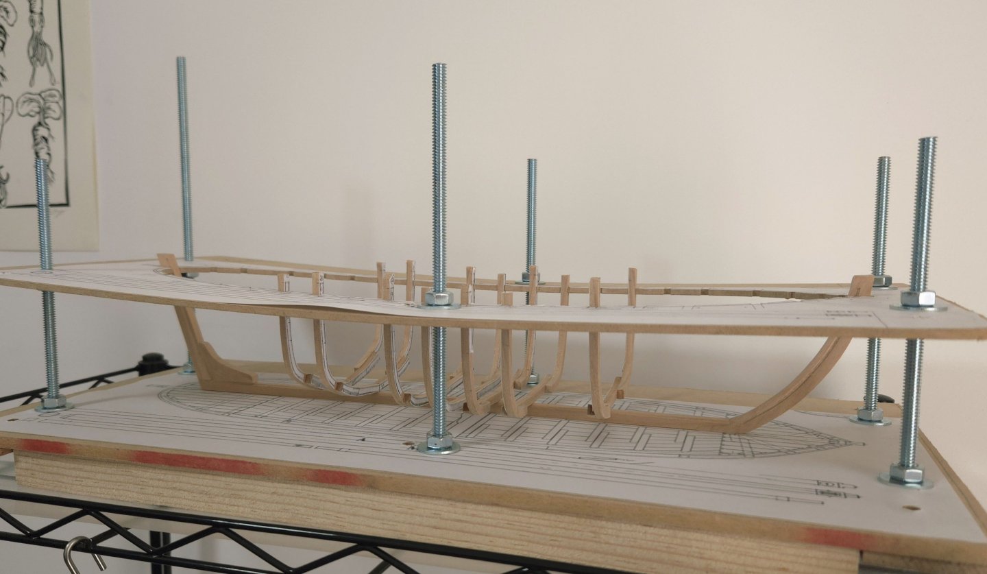
- 141 replies
-
- 8
-

-
- ancre
- Bateau de Lanveoc
- (and 2 more)
-
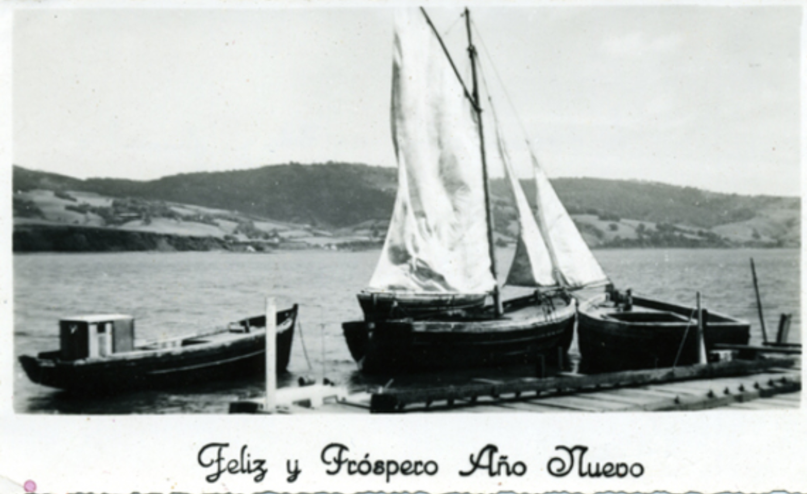
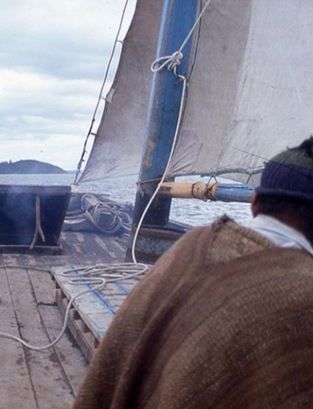
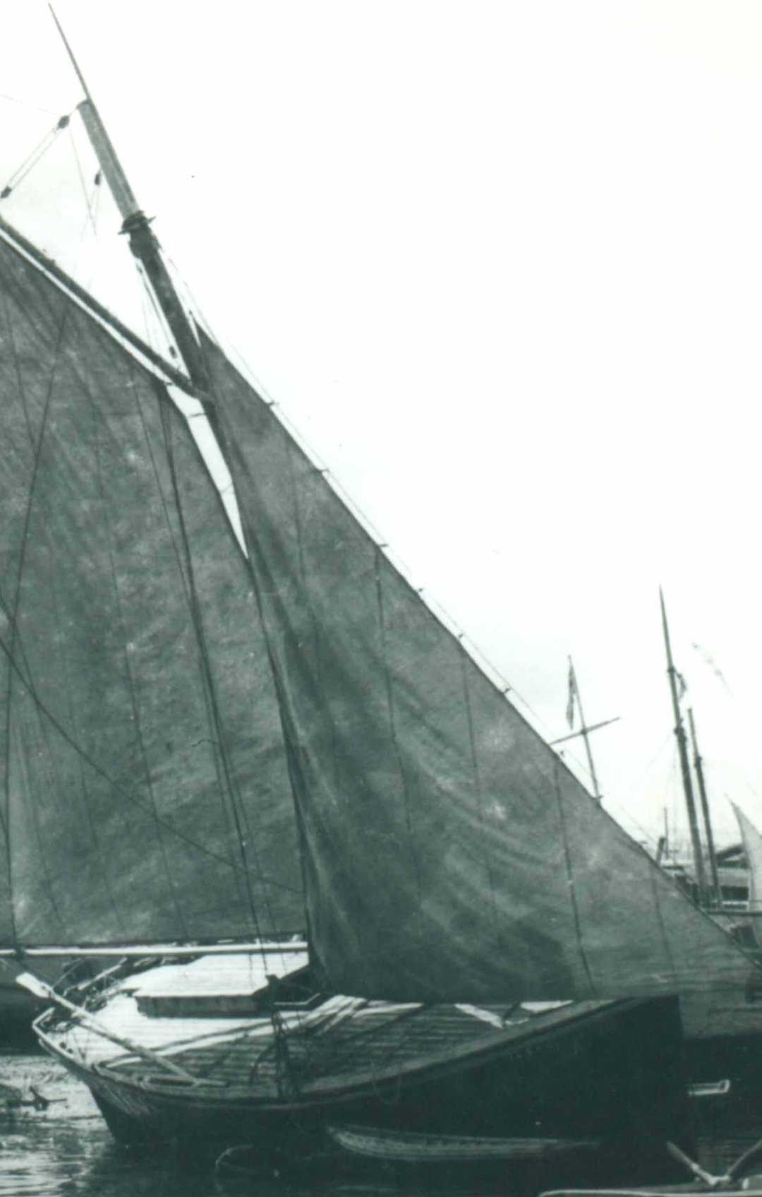
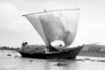
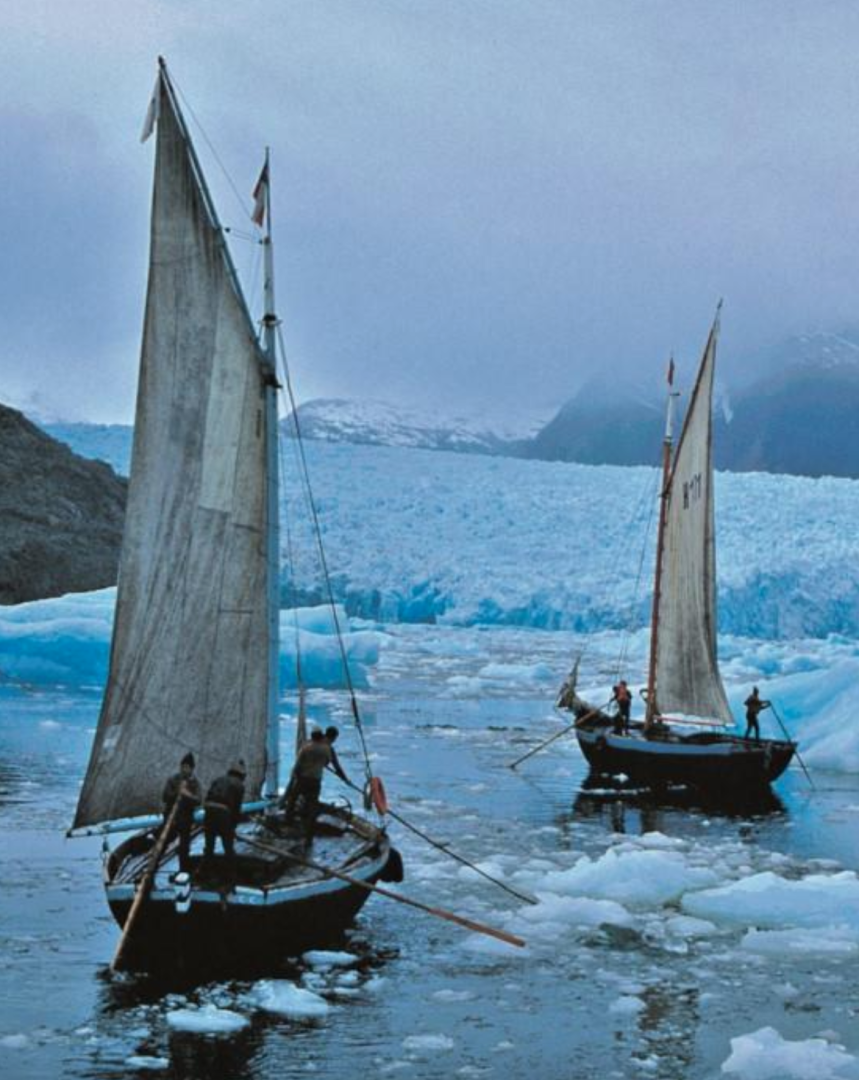
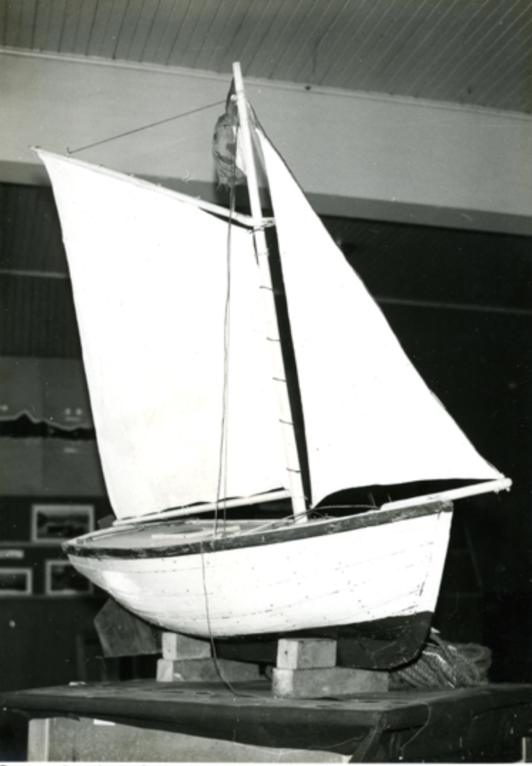
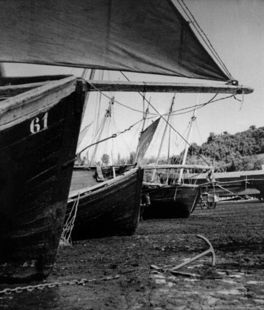
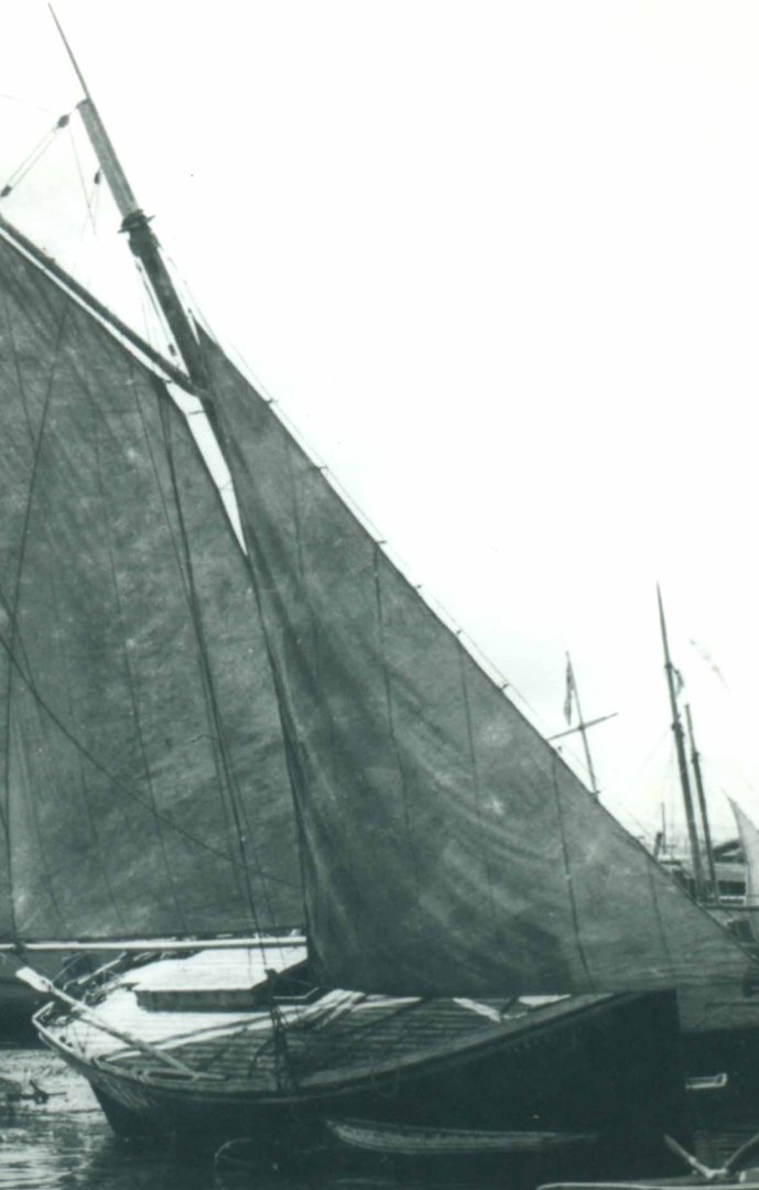
It's been a while since I did a post on the history of the Lancha Chilota, but with the build wrapping up soon, there was a bit more I wanted to discuss: the vessel's transition from quotidian workboat to a symbol of regional identity. One of the more interesting sources online I found was a brief Chilean documentary from 1983 titled "Regata a un ventisquero" ("Regatta to a Glacier"), directed by Domingo Garrido, available on YouTube at: < https://www.youtube.com/watch?v=CDeTRT64kd8 >. The film includes some great color footage of Lanchas under way for a 1983 regatta created specifically to promote the vessel type and Chilote culture. If anyone is interested, the regatta starts around 1:40 in the video. There's some great footage of Lanchas under sail (at times moving a bit faster than I expected, given their tubby proportions) around 2:56, 5:20, and 7:30-8:30, and a shot of some under tow bobbing around like corks in heavy seas around 4:50. The documentary includes a bit of a Lancha interior at 7:45, and has some impressive footage of the Lanchas reaching the San Rafael Glacier--the farthest point reached in the regatta--far to the south of Chiloé and sailing through the ice floes at 8:40-9:30. The 1983 regatta was one of a number that was organized in these years--the detail from a larger photo by Claudio Pino Ocampo, below, comes from a 1986 regatta that went to the same glacier. There's also an interesting, longer documentary about the series of regattas, also available on YouTube and also featuring plenty of great footage, at < https://www.youtube.com/watch?v=dkb-4hmegzs >, as well as a shorter image slideshow that includes some useful context in the description at < https://www.youtube.com/watch?v=ah6feXQemF8 >. As the documentaries make clear, the regattas were extensive productions, lasting 21 days and including stops in a series of ports throughout the region, with performances of traditional dances and displays of traditional handicrafts attending the Lancha flotilla's arrival. Image Source: https://www.museodeancud.gob.cl/cartelera/estreno-documental-exposicion-fotografica-y-lanzamiento-de-libro-sobre-veleras-de-chiloe Given the stunning footage and images that came out of it, these Lancha regattas are clearly interesting in their own right. But they're also interesting because they point to the ways that the role of the Lancha in regional and national culture was changing by the 1980s. As discussed especially in the second youtube documentary I linked to above, the regatta series was officially named the Regata del Once de Septiembre ("The September 11th Regatta"). Long before the World Trade Center attack, in Chile it marked the date of the 1973 coup in which the military overthrew elected president Salvador Allende and installed an authoritarian junta presided by General Augusto Pinochet. The military regime, which lasted until 1990, killed about 3,000 people, tortured and imprisoned tens of thousands more, and pushed about 200,000 Chileans into exile abroad. (Including, incidentally, José A. Garnham, who went to the US and whose book Lanchas chilotas I was unable to obtain but whose website has been a valuable source of information.) During the dictatorship, September 11 was officially celebrated as a national holiday, the "Day of National Liberation," and by the 1980s, the Lancha regattas became a regionally important part of the dictatorship's celebrations. The regattas appear (according to one of the documentaries linked to above) to have been organized chiefly by Empremar, the national state-owned maritime corporation. The regional military commandant--an important figure in the military government--attended the regatta's inauguration festivities, and the Chilean Navy provided crucial support for the lanchas on their voyage. Although I haven't been able to find much on the topic from my rather cursory searches, the regattas seem to have been part of a broader effort by the dictatorship to bolster its own legitimacy by (selectively) associating itself with local, regional, and national traditions. Through the September 11 regattas, the Lancha Chilota--fast disappearing as a workboat--was used as a tool for these efforts, promoting a certain idea of Chilote traditions as contributing to the grandeur of Chile as a whole. This selective process is clear when we pay attention to what was and was not promoted by the state. Important Chilote traditions like the minga, a form of community mutual aid with indigenous origins, don't seem to have been promoted much if at all (possibly because they cut against the government's emphasis on promoting market relations). Meanwhile, the Lancha Chilota could readily serve as a symbol of Chilotes as sturdy, stoic, and hard-working people, ready to contribute their maritime skills, their labor, and their rich cultural heritage to the nation. At the same time, the dictatorship could show itself to be working to preserve distinctly Chilean traditions. Efforts to promote and preserve the Lancha through the regatta carried with them a set of ideas about what Chilote identity and history meant, in ways that were at least amenable to the political project of the dictatorship that organized the regattas. This is particularly notable given the dictatorship's economic interests in the Chilean south, as well as Chiloé's longstanding isolation from the rest of Chile. As I've noted much earlier in this thread, Chiloé was marginal to the Chilean economy and culturally isolated for centuries, with Chilotes often barely considering themselves Chilean. Things began to change in the late nineteenth century and early twentieth century with the expansion of the lumber industry--the same wave of development that led to the development of the Lancha Chilota--but, as Anton Daughters argues in Memories of Earth and Sea (2019), the region remained a world apart, marginal and relatively impoverished, well into the 20th century. (Incidentally, these conditions are why the Lancha Chilota remained in use for so long.) The dictatorship saw the Chilean south as an untapped source of potential development and invested heavily in the region. It constructed a major highway through it, the first in the region, and, as Daughters highlights, aggressively promoted the development of a massive fish farming industry centered in Chiloé. These changes led to the effective demise of the Lancha Chilota. As Neil Hollander and Harald Mertes found, visiting Chiloé for research for The Last Sailors: The Final Days of Working Sail (1984), the region changed dramatically in just a few years, with the Lanchas falling into disuse as trucking took over lumber transport (and, undoubtedly, with the small farm economy declining with the rise of fish farming, as Daughters shows). Many Chilotes themselves were also quite happy to see Lanchas go, with one miserable captain explaining to Hollander and Mertes that sailing a Lancha was laborious, cold, and wet work--between the region's frequent rain and the ocean's spray, everything was constantly damp, you froze if you were at the helm, and you choked on smoke if you went down into the hold for warmth. One informant boasted that he would be selling his for firewood. The state's promotion of the Lancha regattas, just as the Lancha was disappearing due, ironically enough, to the state's own development policies, shows another side of the dictatorship's interest in the region, one that focused more on promoting elements of regional culture and tradition and connecting them to the state and nation. (Similarly, although my sources are limited, the dictatorship also seems to have promoted the construction of a replica of the schooner Ancud, an 1840s Chiloé-built warship that claimed Chilean sovereignty in the Straits of Magellan. The dictatorship was undoubtedly interested in the replica due to the broader context of the Beagle Crisis, a border dispute with Argentina over the Straits that nearly boiled over into open war in the late 1970s. For the state, the replica Ancud was a way of affirming the deep roots of Chile's claims to the far south, while emphasizing Chiloé's place in national history.) Placing the Lancha regattas into this context, then, it seems clear that the Lancha regattas of the 1980s were meant to symbolize a broader project of bringing Chiloé into Chile's national history, in part by promoting a rather romanticized image of the Lancha--hence the stunning photos with the glaciers. The regattas were an important part in the Lancha's change from quotidian workboat to an object of heritage or nostalgia. Yet, at the same time, it would be a mistake to think that the dictatorship was solely responsible for this change, which in part reflected a longer history of positioning the Lancha as a distinctive part of Chilote identity. Looking over the photographs of Lanchas digitized in the Chilean National Digital Library, I was struck by how many of them, dating from well before the dictatorship, were in fact postcards. Photographers in and around Chiloé, especially in Puerto Montt, had clearly been struck by the distinctiveness of the Lancha and began to commercialize images of them. Postcards like the one below were used to send holiday greetings (in this case for a happy and prosperous new year). (See also the letters, visible by clicking "Visualizar," here and here). It would be very interesting to know if these were mostly used by Chilotes themselves who traveled to the mainland for work, but in any case, the image of the Lancha undoubtedly circulated beyond Chiloé itself and began to become more widely recognized as something distinctly Chilote. Source: https://www.memoriasdelsigloxx.cl/601/w3-article-2898.html Meanwhile, local history associations and the like had already started promoting the idea of the Lancha, likely as a way of affirming the distinctiveness of Chiloé's own traditions. The Provincial Institute of Chiloé History, for instance, seems to have organized a number of nautical expositions in the 1960s. Alongside models of ocean liners and battleships, the expositions also appear to have included models of Dalcas (the sewn-plank canoes of indigenous origin that predated the Lancha) and of Lanchas, such as the model below from the 1966 exposition. Source: https://www.memoriasdelsigloxx.cl/601/w3-article-3073.html To some extent, the regattas of the 1980s seem to have represented an intensification of these existing efforts at preservation and commemoration, possibly (although this is really a guess based on extremely limited sources) with an added dose of nationalism. Yet if it's clear that the Lancha shifted from a workboat to an object of nostalgia as it faded from use, it's less clear that the regattas really contributed directly to the Lancha's preservation. While the regattas used the Lancha as a symbol, I haven't seen anything to suggest that they sponsored Lancha construction or the like. It seems to have only been in the 2000s that local stakeholders and state organizations began to promote the preservation of Lancha and wooden boat building techniques in Chiloé, by which time there were very few builders or vessels left. Local museums have done work to connect with and publicize traditional builders. A number of new lanchas have been constructed--at times with the support of public heritage programs--as private tour boats, like the Voladora (see: here and here) or as municipally-owned heritage vessels (as discussed here). Indeed, one report from just yesterday discusses how a mini-lancha was sent to represent Chile in an international maritime event in Galicia, Spain (Link). Of course, not being working boats, these vessels are often different in a number of aspects from more traditional lanchas, but they have helped keep the basic design going, and continue to highlight the Lancha as an iconic element of Chilote identity. These efforts to promote the Lancha undoubtedly reflect not just the interest of Chilotes in preserving something that was already recognized as a distinctive part of their culture, but also the growing tourism industry in Chiloé. So, why does this matter? Well, first because I think it's important to reflect on how and why "traditional" working vessels become recognized as heritage (and, when possible, why they don't--the Chalupón, for instance, was also an important vessel in Chiloé and the same period, but seems to have received far less attention than the Lancha, for reasons that aren't entirely clear to me. Perhaps the type was used in different ways or was employed more often further south, away from Puerto Montt where most photography studios were, and it thus didn't become as important a symbol early on through postcards, although I'm just spitballing here). Rather than something that naturally just happens when something is old enough, the creation of heritage is the product of choices by different actors with their own goals. As a modeler, this also helps me to understand what I'm doing when I'm modeling. I don't think that making a model of a Lancha means buying into the sort of romanticized, nationalist image of them that the dictatorship promoted, for instance, nor do I think a bit of a romanticized view of workboats is necessarily a bad thing--they're certainly very aesthetically appealing! But knowing how the Lancha has been used for those purposes shapes what I want to do with this model. This is part of the reason I've tried, in this build log, to discuss the Lancha's history and to contextualize its development and origins--to try to use the model and its building process to show something about how people experienced, shaped, and understood the processes of historical change that they found themselves living through.

- 312 replies
-
- 8
-
-
- Chile
- Latin America
- (and 6 more)
-
Very nice job!
-
Very nice job!
-
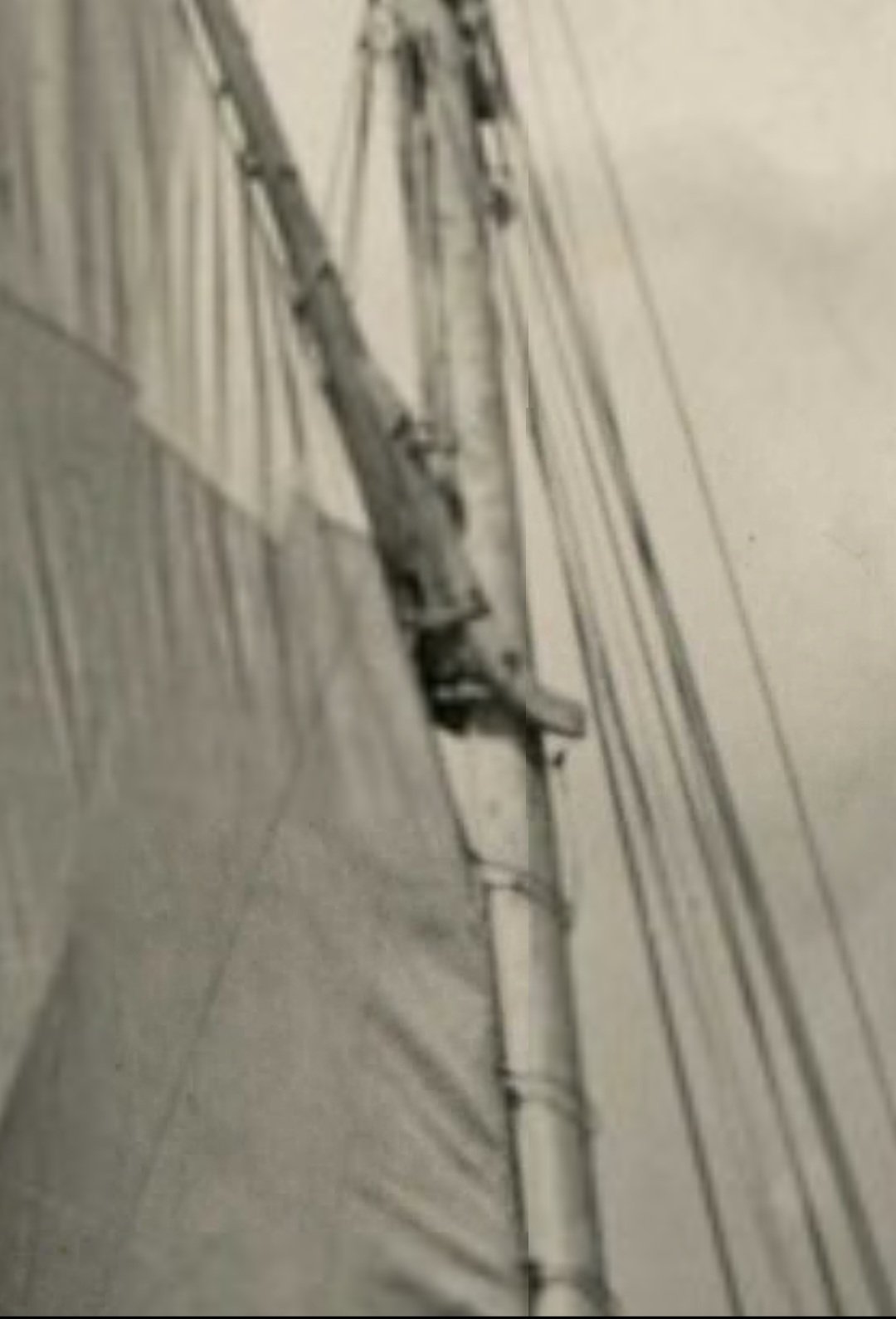
Digging around a little more, I found the photo detail below: Source: https://www.bibliotecanacionaldigital.gob.cl/bnd/629/w3-article-613541.html It's a bit blurry and hard to see, but it almost looks like there are protruding bolts through the gaff jaws that would keep the throat lashing from sliding back. I've definitely seen such bolts on some lanchas, though not all (which is why I didn't add any on mine).
- 312 replies
-
- 6
-
-
- Chile
- Latin America
- (and 6 more)
-
Thanks, @MAGIC's Craig! That's a very good point, and something I was a bit concerned about when I was adding the sails, given the taper aft of the gaff jaws. My own sailing experience is extremely limited, so it's very interesting to hear how this issue would be resolved on an actual vessel (by the way, thanks for sharing the photo, the colorful sails look great). So far, I haven't found a definitive answer. I had interpreted the photo you link to as showing just the line around the gaff jaws at the throat, and as having a mast hoop laced to the sail a short distance below the throat, but I may be mistaken. I also don't think I see any additional lines at the throat in the photo linked below (which can be enlarged by clicking the "visualizar" link). https://www.bibliotecanacionaldigital.gob.cl/bnd/629/w3-article-164310.html When I was building it, I had the thought that passing the line through an eyebolt on the underside of the jaws might work, but I didn't see any clear evidence of that. I'll keep looking for something, though, as it definitely is something that they would have had to deal with on an actual lancha.
- 312 replies
-
- 3
-
-
- Chile
- Latin America
- (and 6 more)
-
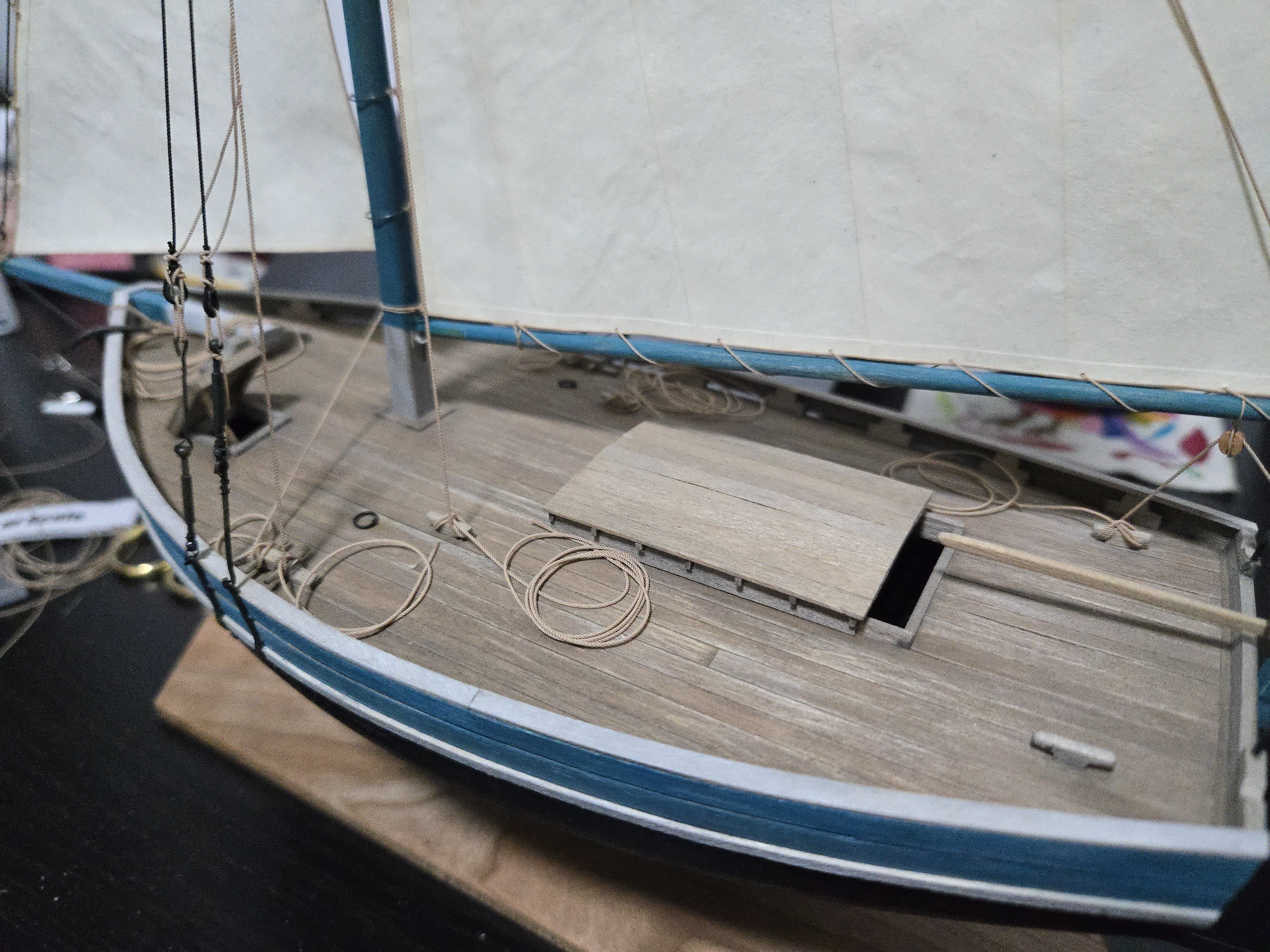
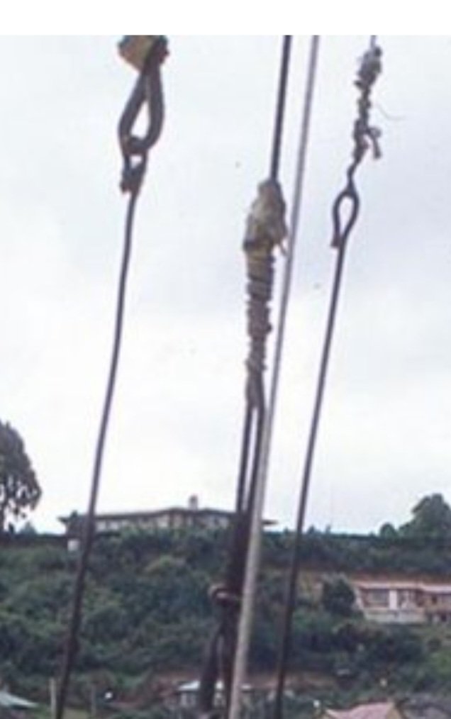
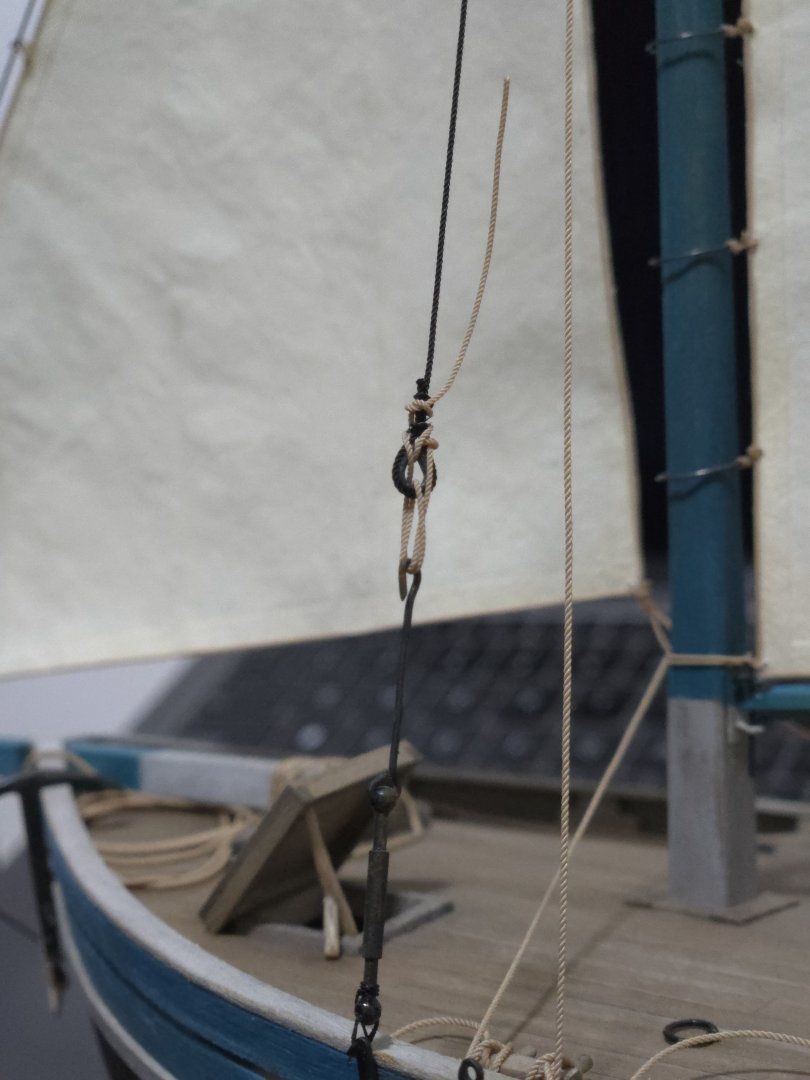
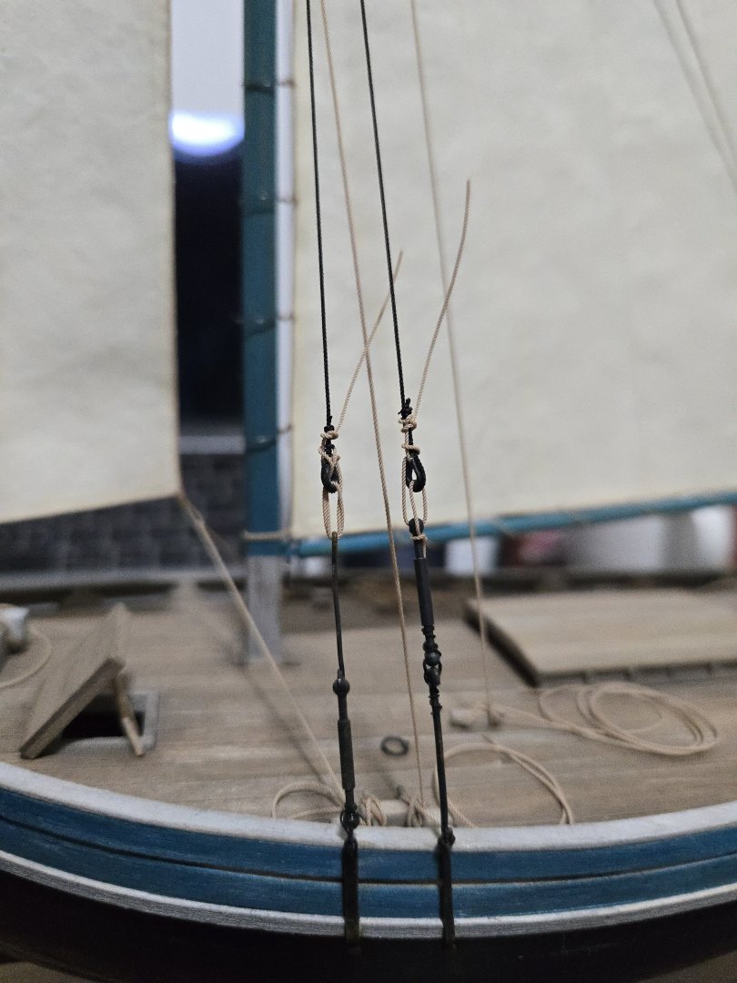
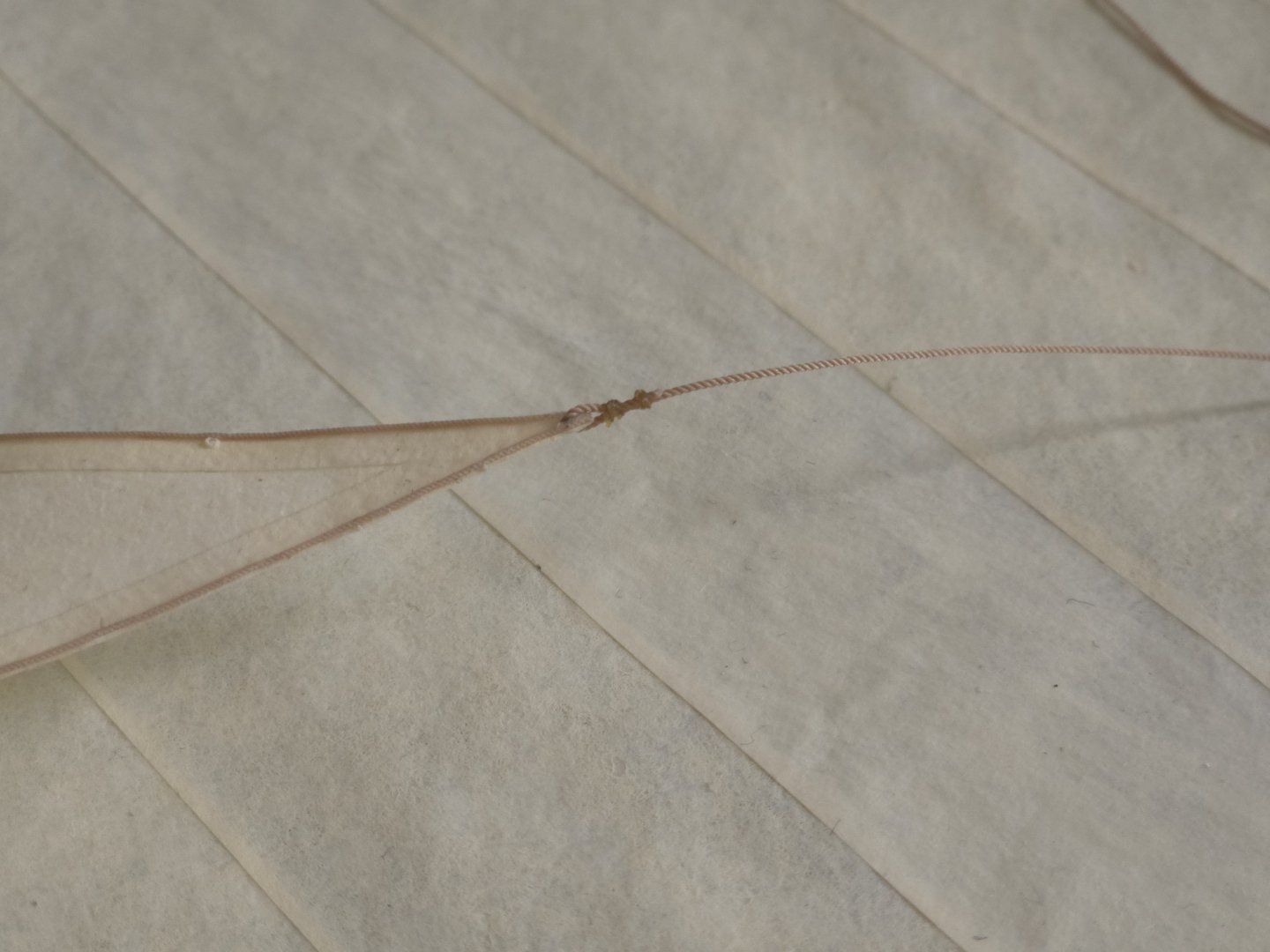
I was able to find the time to redo the lanyards, adding an extra loop to each and doing a better job of tying everything off. Looking at photos of lanchas, I was struck by the way that lanyards and the like seem to have been tied off in rather haphazard ways rather than with more typically "maritime" knots, like in the detail below: Source: https://www.carlosvairo.com/galeria-puerto-montt-lanchas-chilotas While I wasn't able to get knots quite as tight, the added knots will look more accurate than before. Rather than secure these with superglue and run into trouble later if I have to redo them due to the line stretching, I have secured them with diluted white glue, and they should be more malleable if moistened in the future for retying. They've still been left a bit long awaiting a final trimming, although the "tails" at least point downward with gravity now. Everything has been temporarily placed on the deck for now, although I still need to glue it down. The excess line also still needs to be properly coiled/piled up. But, with family about to visit, I won't be doing any of these finishing touches for a couple weeks.


- 312 replies
-
- 11
-
-
- Chile
- Latin America
- (and 6 more)
-
Thanks, Paul! Thanks, @wefalck! I agree about the lanyards, I think I can only do two wraps through the aft shroud thimbles/hooks because the hold in the end of the turnbuckle is a bit too small to fit more. In hindsight I should have drilled it out at an earlier point in the build.
- 312 replies
-
- 3
-
-
- Chile
- Latin America
- (and 6 more)
-
Thanks, Keith! It's nice to see it all coming together. I figured that I may as well go ahead and add the shroud lanyards. So far they're not glued in place and I've left some excess, so I can adjust if necessary. Figuring out how to properly do the lanyards was a little tricky, given that these aren't deadeyes, just thimbles and hooks. I've also loosely coiled the rope ends, also without glue, mainly to tidy up the deck a bit. The miniature rope doesn't naturally lay in a pile the same way the real rope does, so I'll need to figure out a better way to pile it up and glue it in place. I also did decide to replace the sheet with .5mm rope, down from the original .6mm. I think it looks more natural running through the 4mm block, and the knot is a lot less bulky.

- 312 replies
-
- 6
-
-
- Chile
- Latin America
- (and 6 more)
-
Very nice work! The "bite" torn off the roof is an especially excellent detail.
- 457 replies
-
- 5
-
-

-
- sternwheeler
- Hard Coal Navy
- (and 1 more)
-
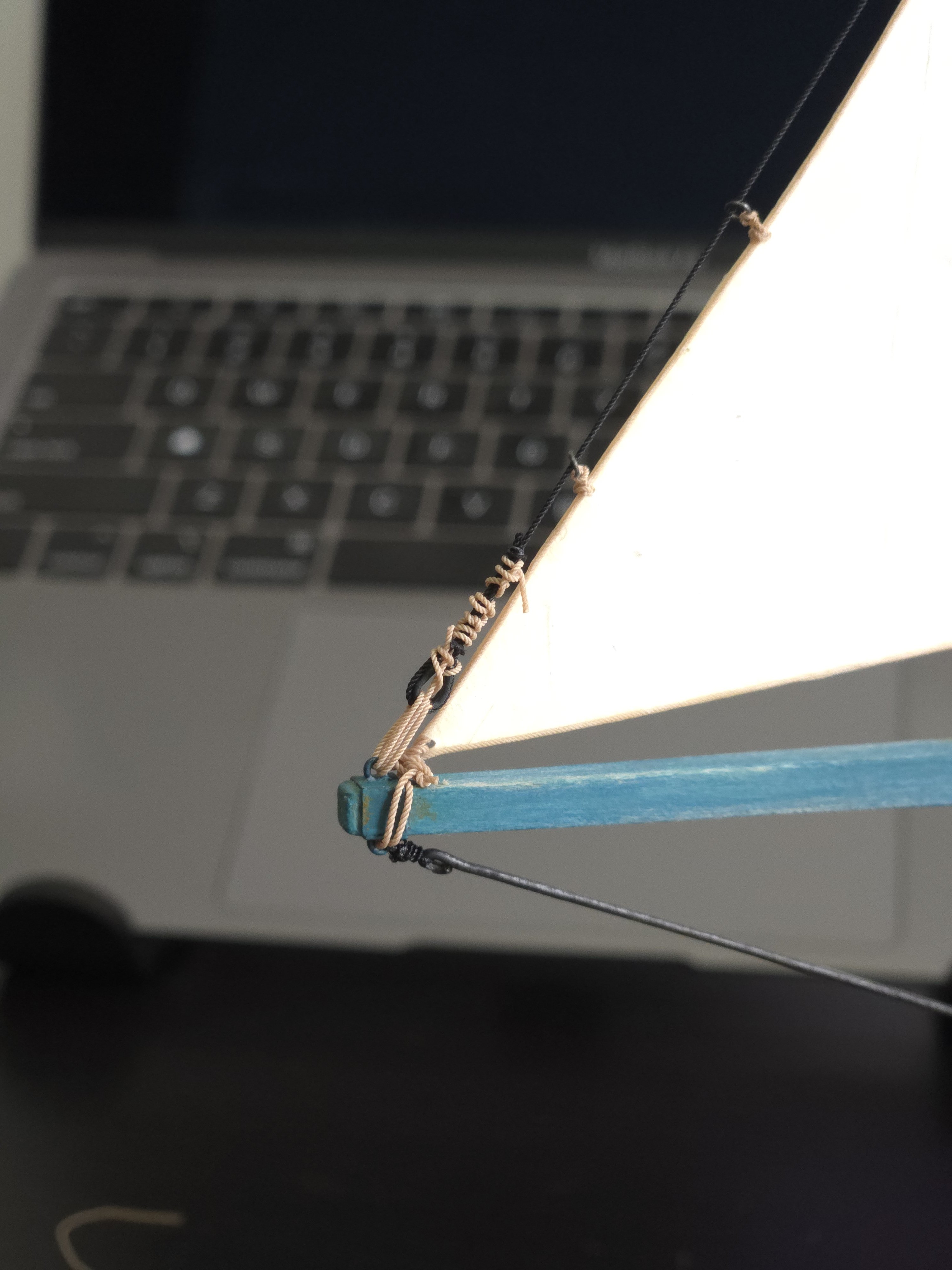
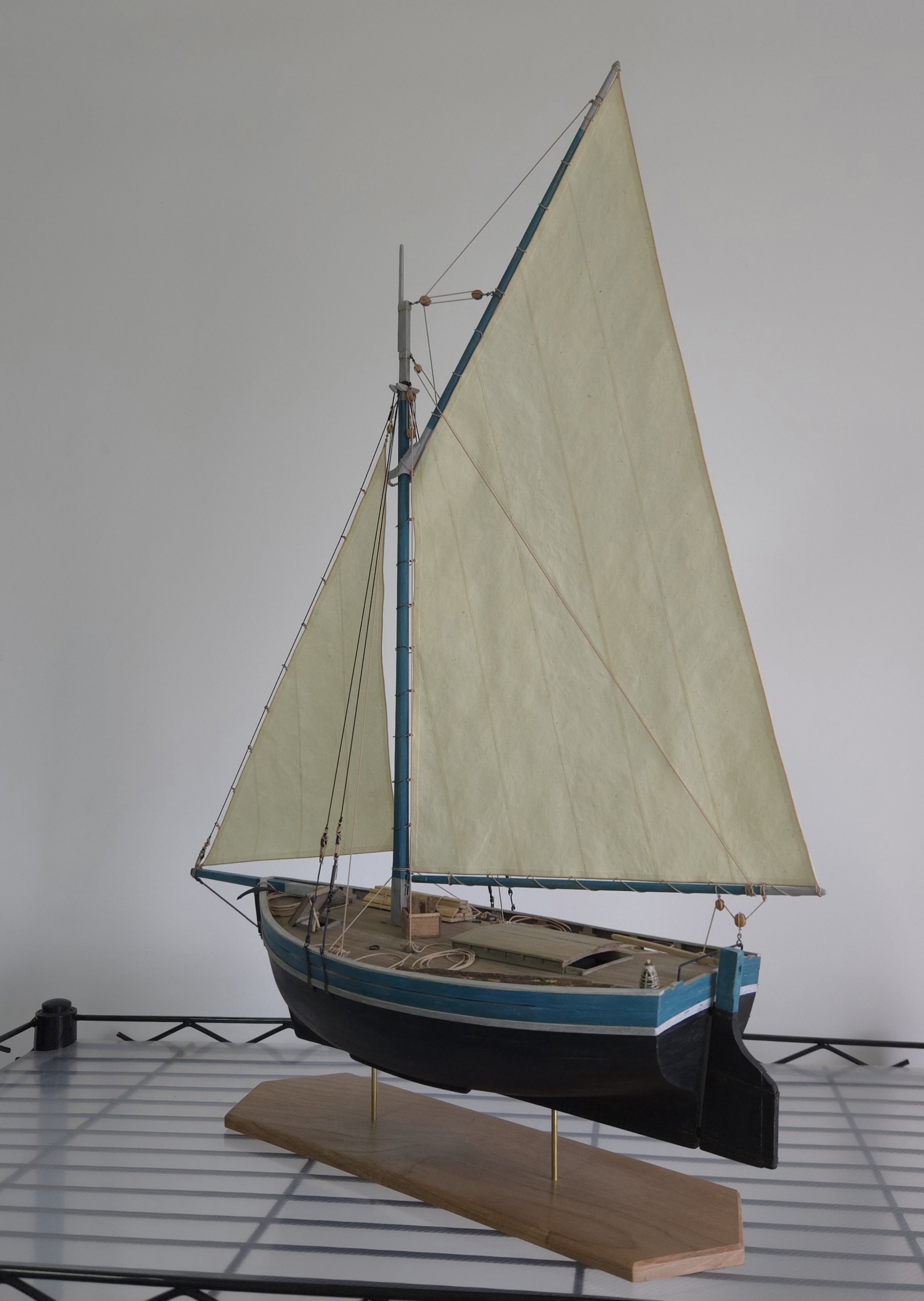
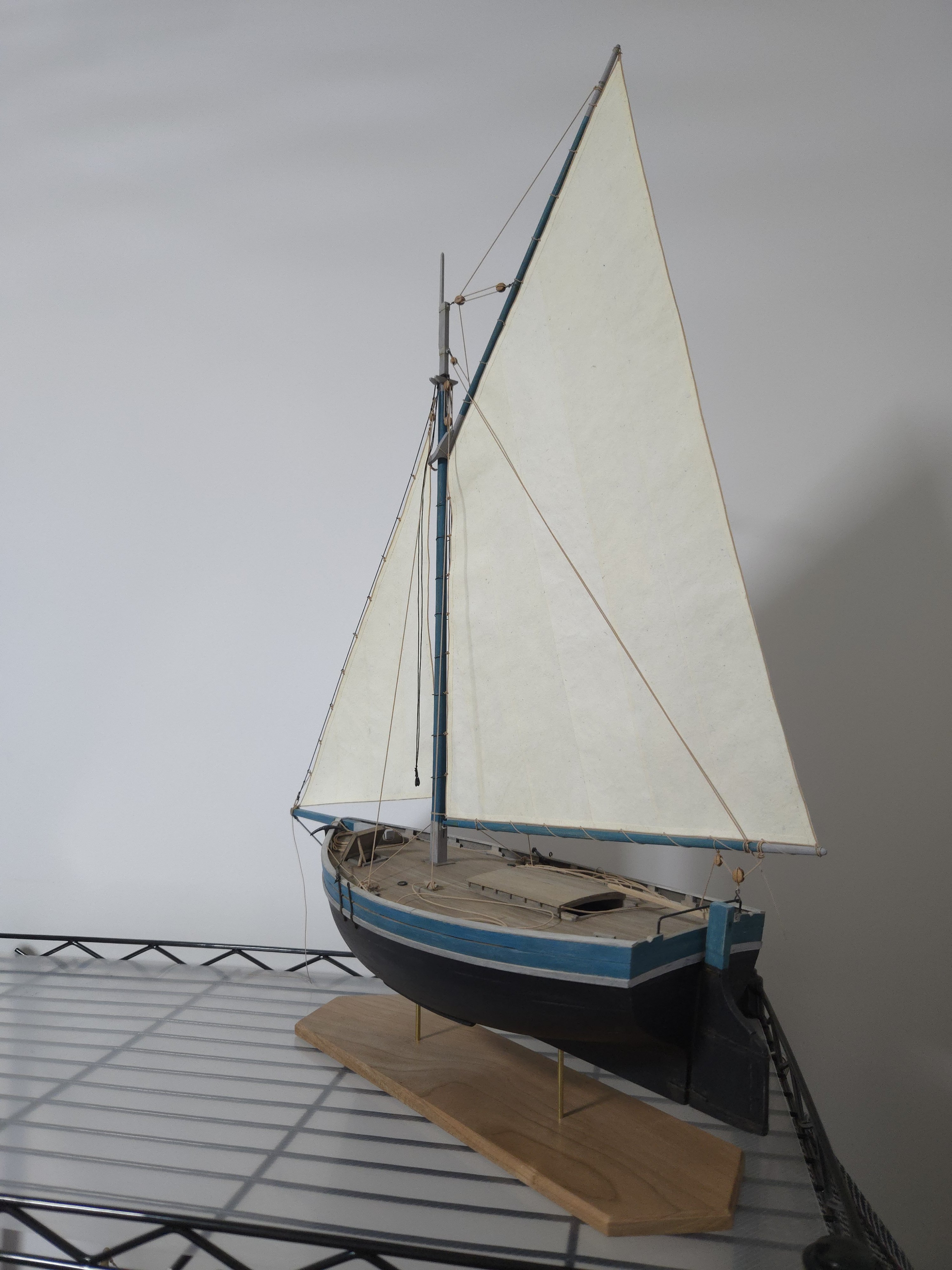
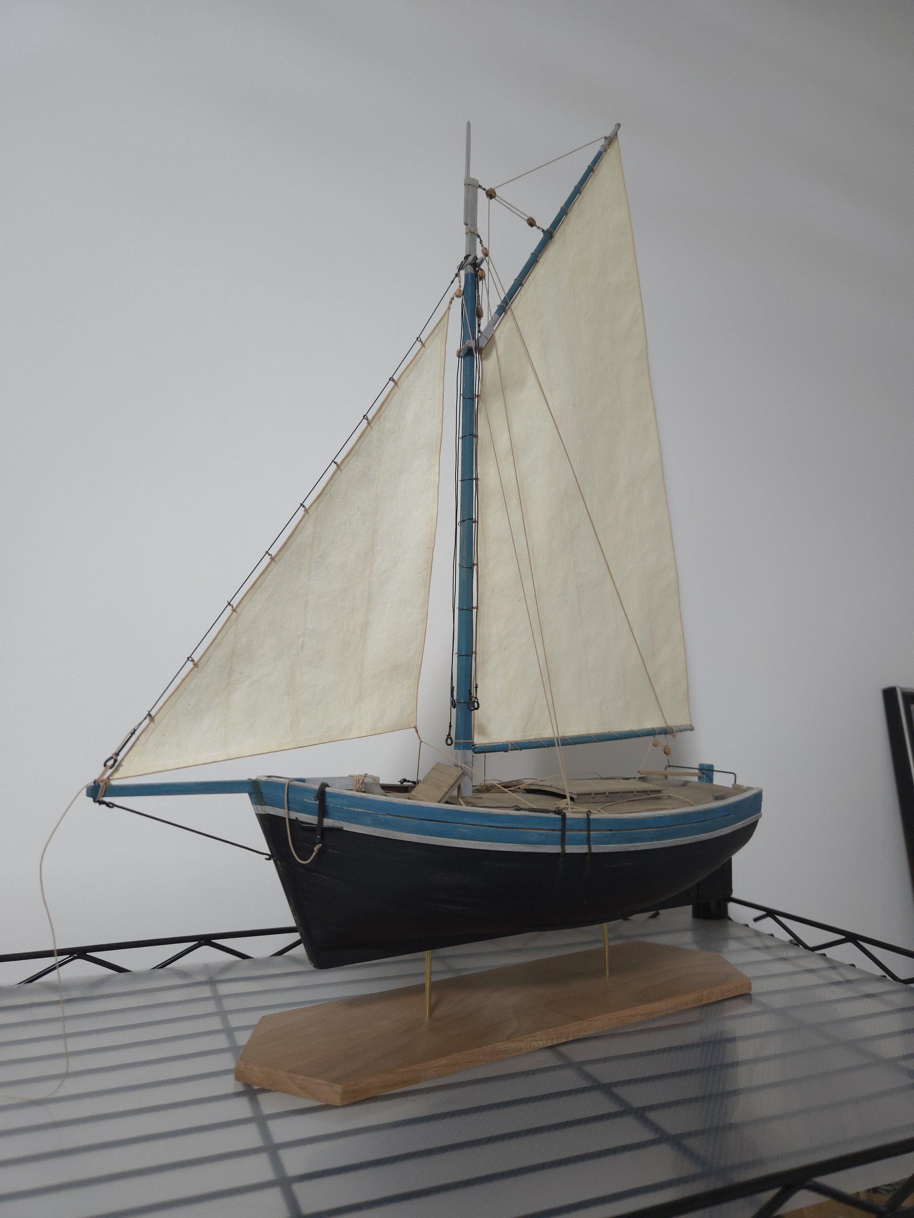
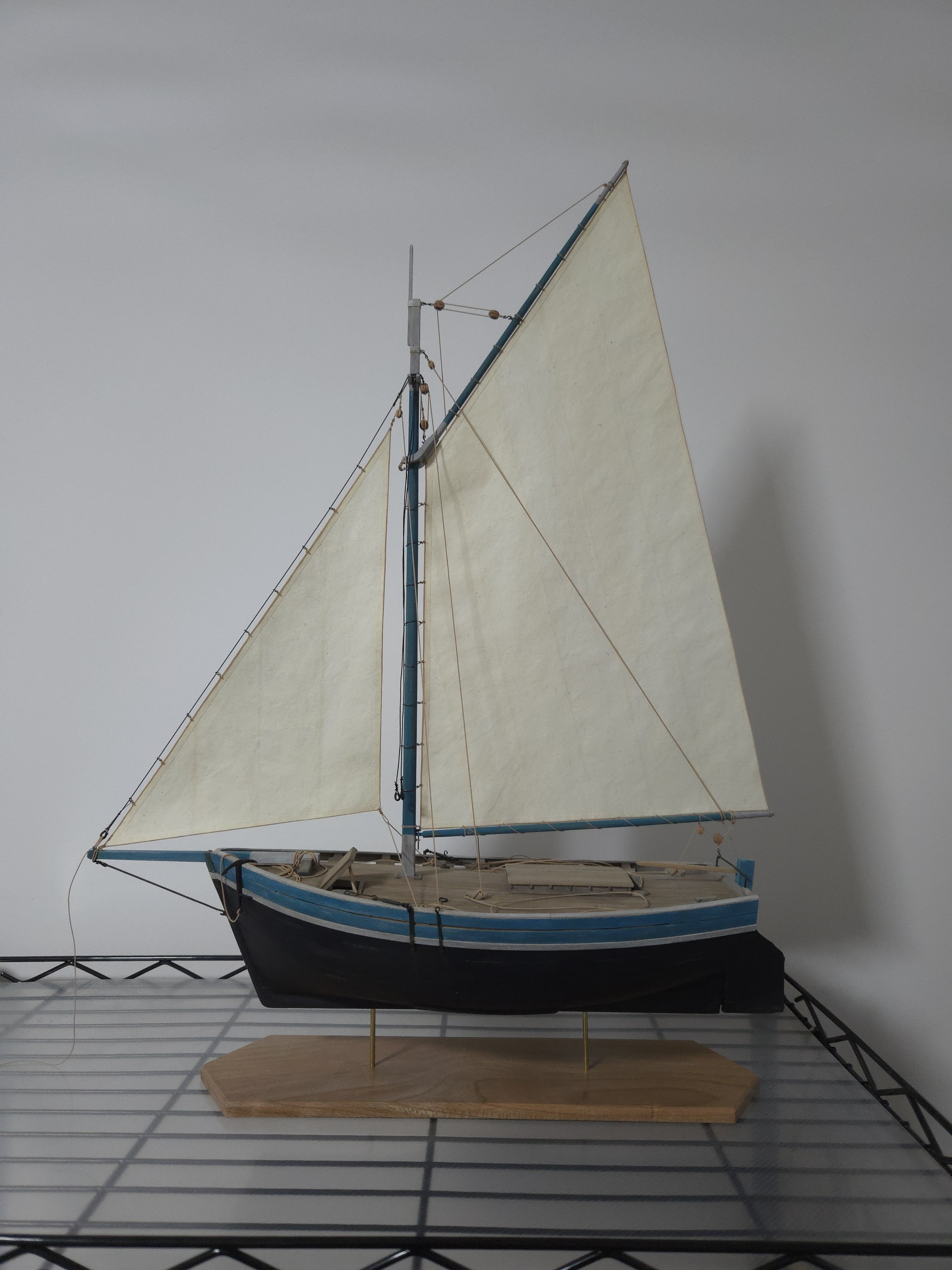
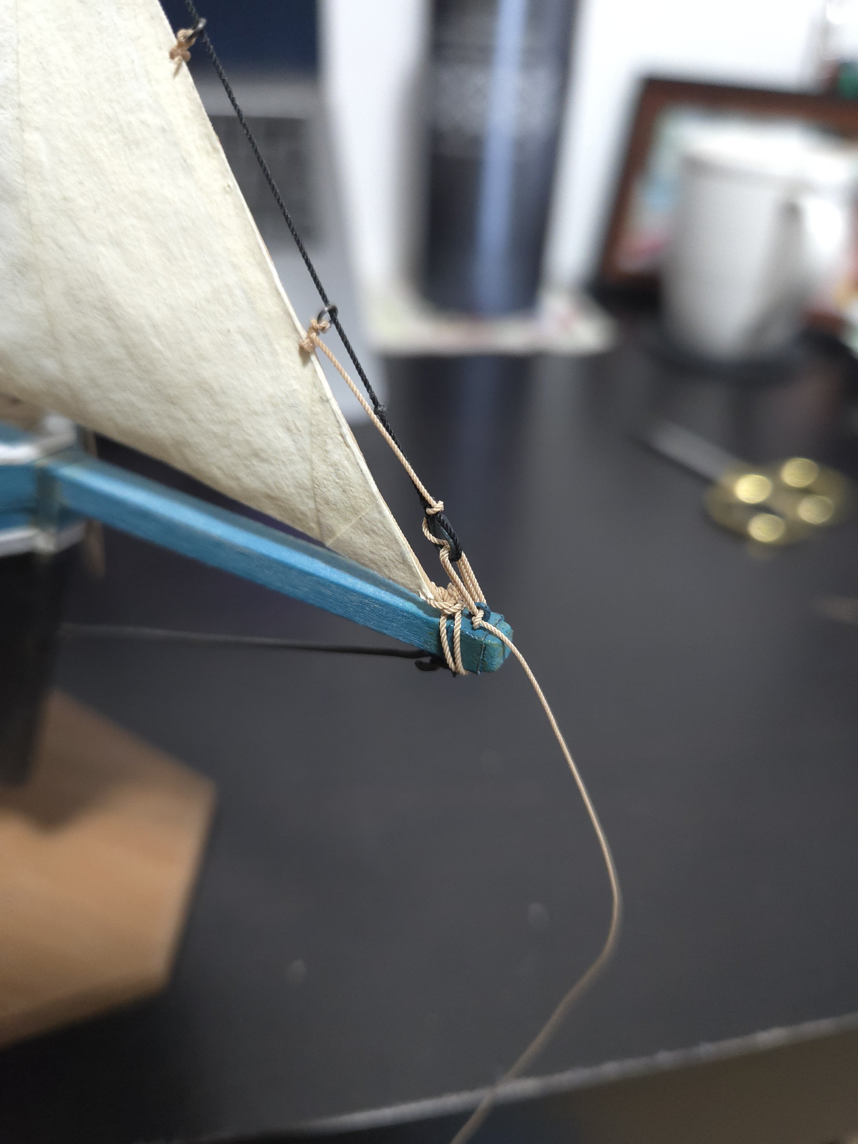
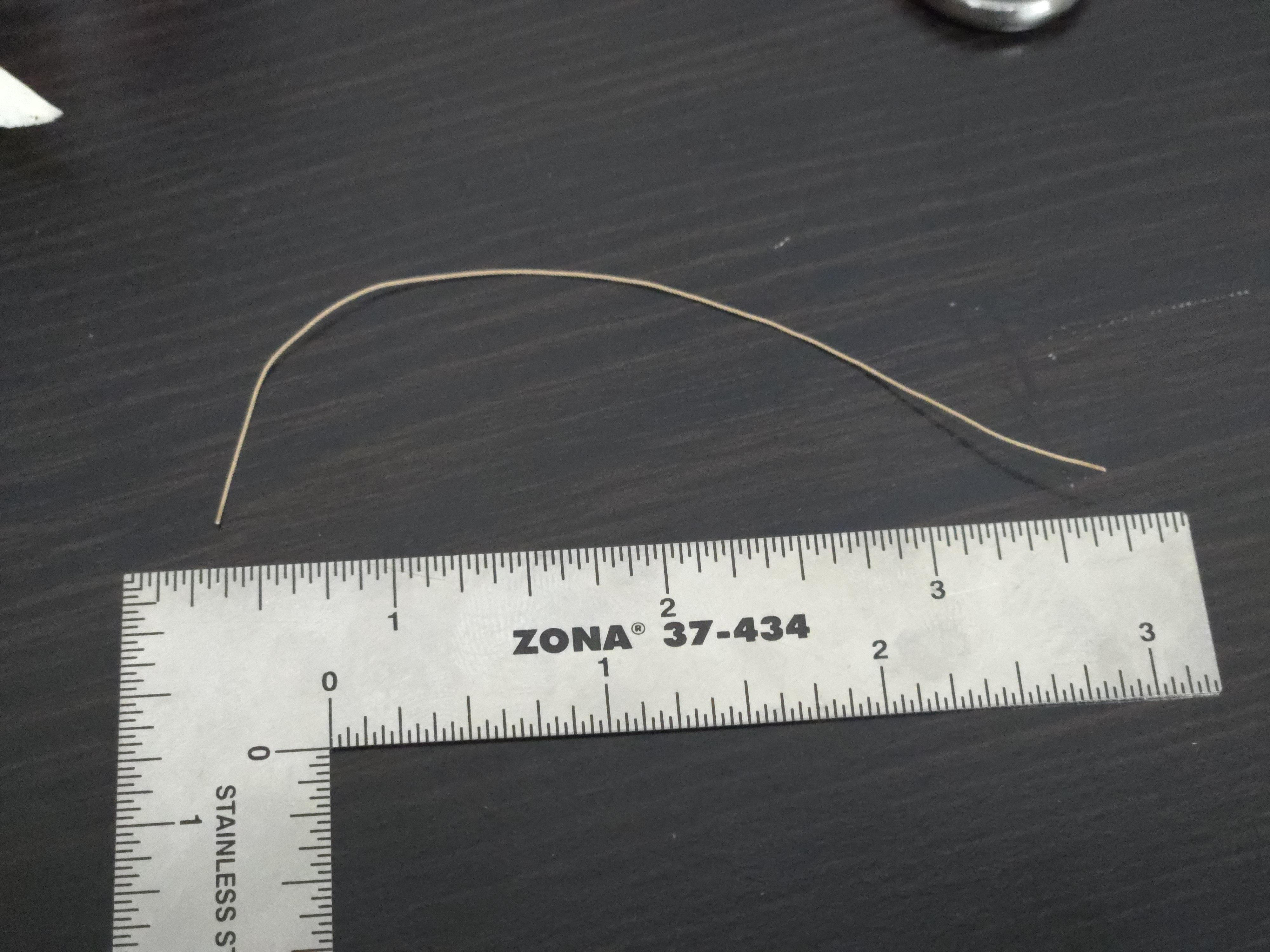
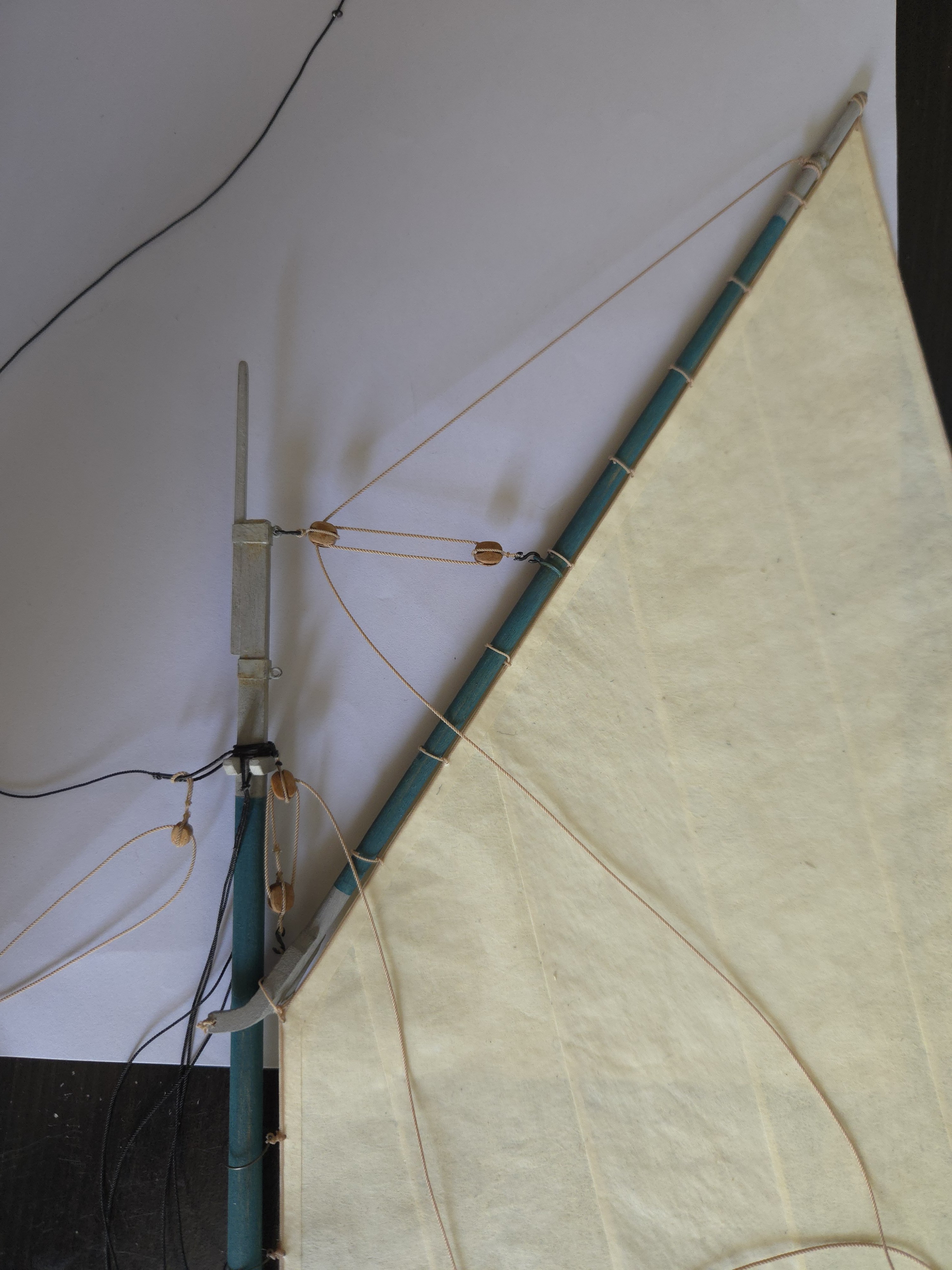
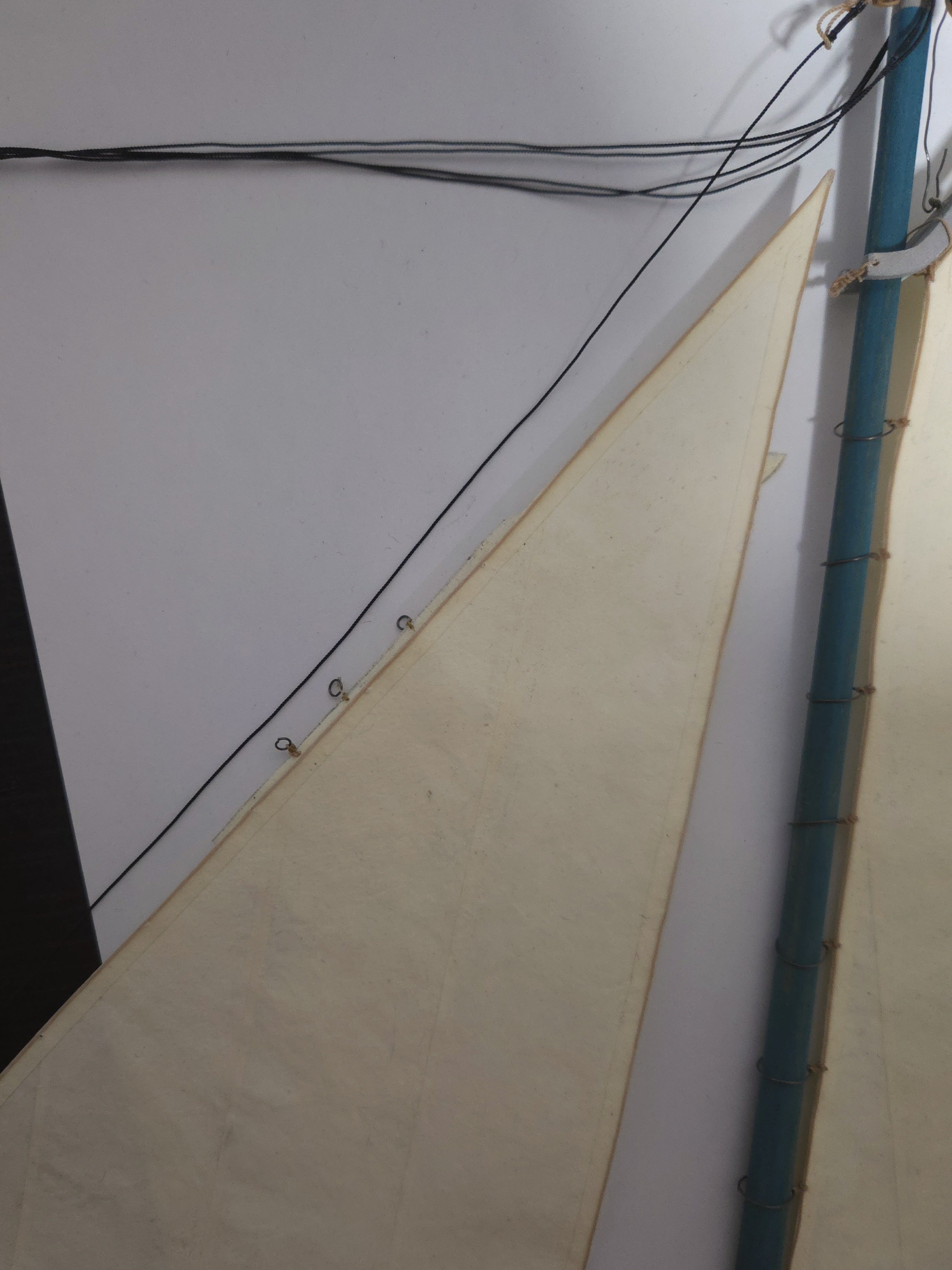
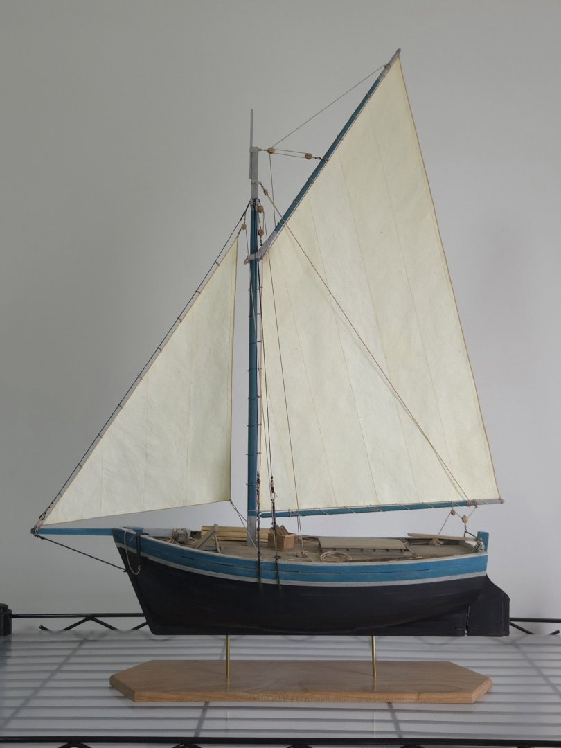
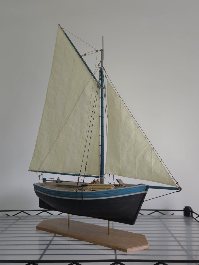
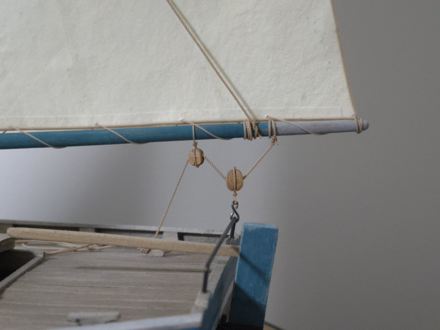
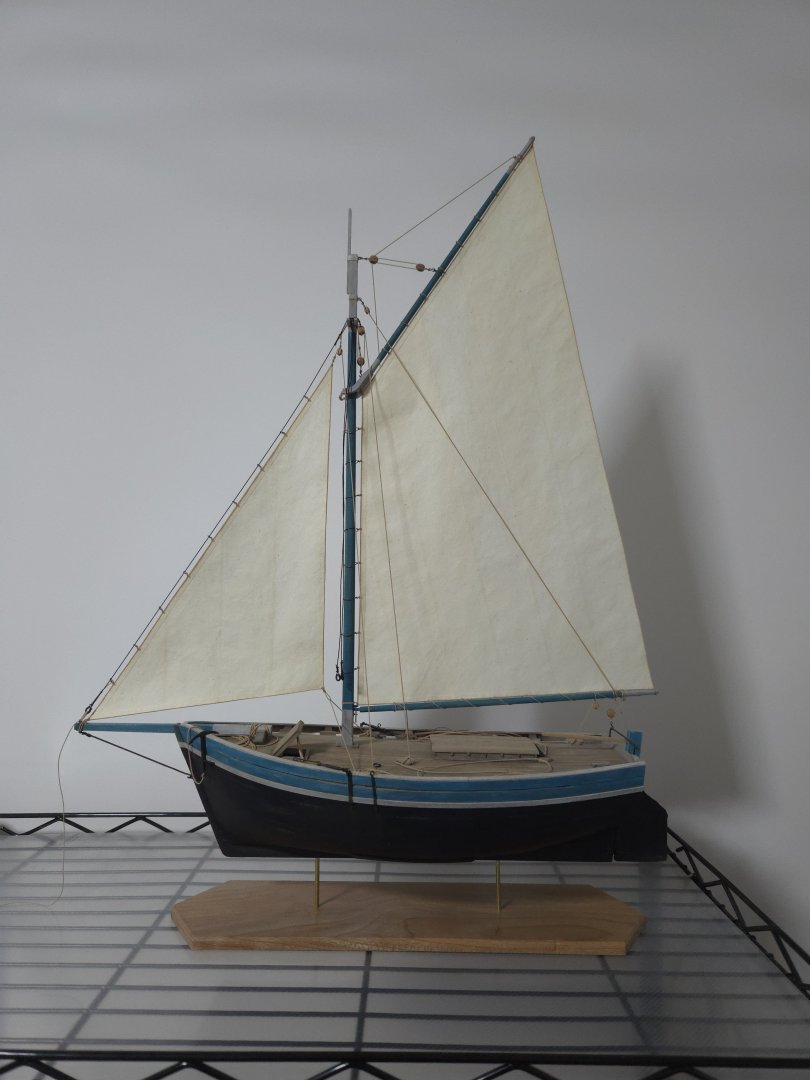
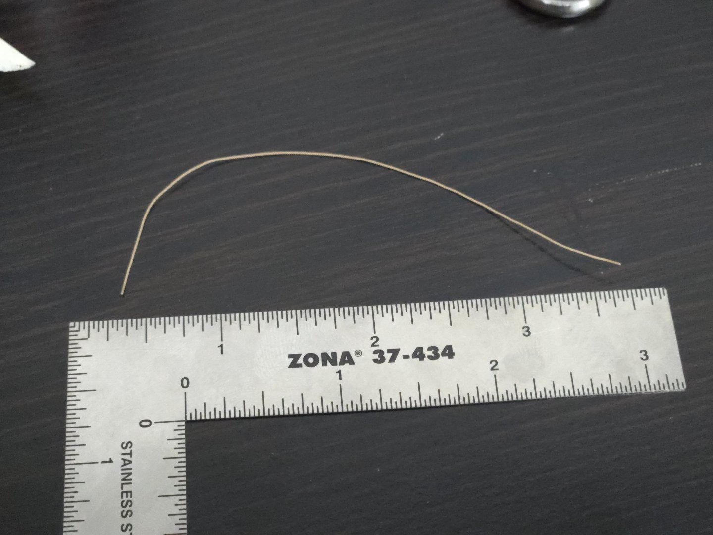
Bending the jib to the forestay was a little tedious but nothing too difficult, just a lot of tiny knots. I was lucky that they all turned out all right. After finishing, this was the total amount of .35mm rope that I had left: After getting as much set up off the hull as possible, it was finally time to step the mast. This was a very exciting step, as I finally got to get a good look at the model with sails in place. After looking at quite a few photos and other build logs and the like, I did my best representation of the lanyard joining the forestay to the bowsprit. I also tied off the tack of the jib, the rope for which, following photographed examples, wraps around the bowsprit (I threaded it through the lower eyebolt to make doubly sure it would stay in place, although this aspect wasn't very clear in photos). For now the lanyard has been left long, so I can adjust it if I need to. For the lifts, I ultimately decided to go with the .5mm rope instead of. 45mm. I think it definitely looks better, but I'm still debating whether the mainsheet should be cut off and swapped out for one made of .5mm rope instead of. 6mm, I feel like it might just look a little too bulky. One end of the lifts (which, following photos, are simply tied around the boom, rather than being fixed to a cleat or something) has been left long for now so that I can easily tighten it if the line starts sagging as it stretches. At the moment, the line is all very long and just loosely piled on the deck. I need to figure out a convincing way to leave it--they definitely didn't use neat coils on these vessels. I also need to tie off the shrouds with lanyards, although this might make more sense to do after finalizing the running rigging so that I have more room to work. I have to admit that I'm very pleased with how this build is coming along. Thank you very much to everyone who has added a like, left a comment, answered questions, or otherwise offered support on this model.


- 312 replies
-
- 9
-

-
-
- Chile
- Latin America
- (and 6 more)
-
Nice work! While I haven't used much walnut, it's often said to have too pronounced a grain to work very well at scale. Some people seem to get a good finish with it though, it depends on what sort of look you're going for and whether you'll be painting it. In my limited experience, mahogany has the same grain issue and is rather stiff, making it hard to bend and twist. The limewood is probably very similar to what is called basswood in the US, searching the forum under that name will probably generate more results. It's very easy to work with, but is soft and tends to fuzz a bit when sanded.
-
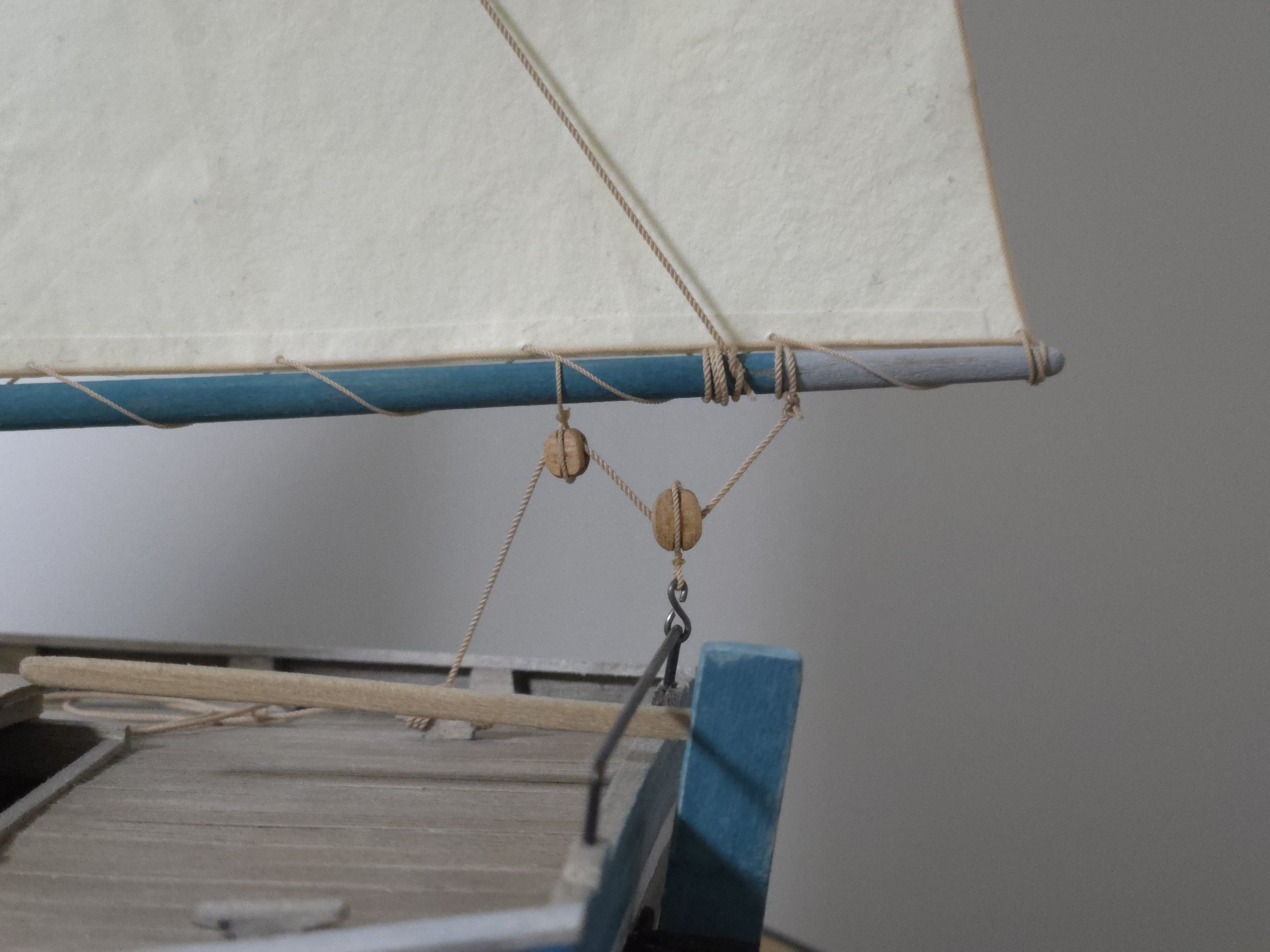
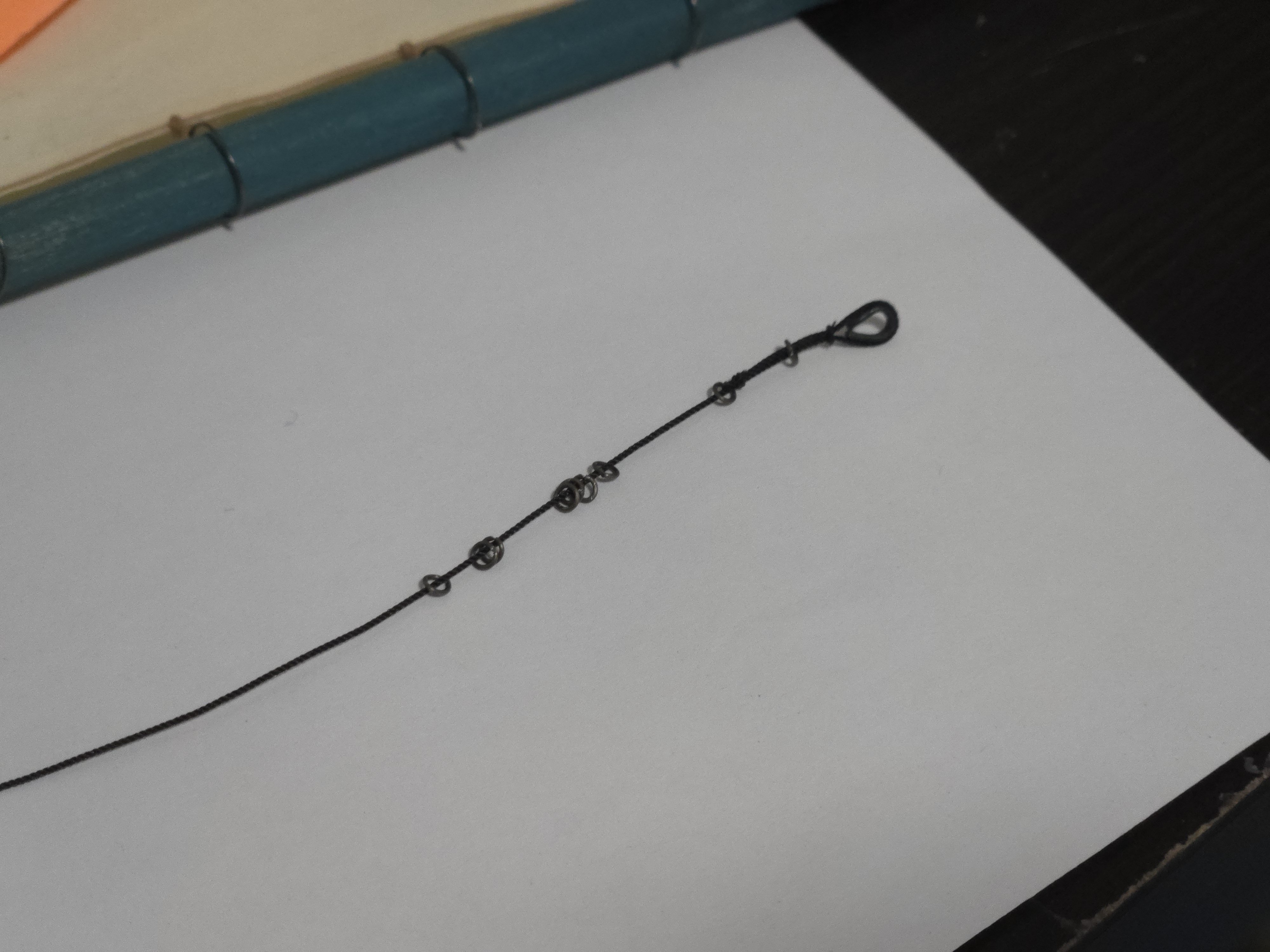
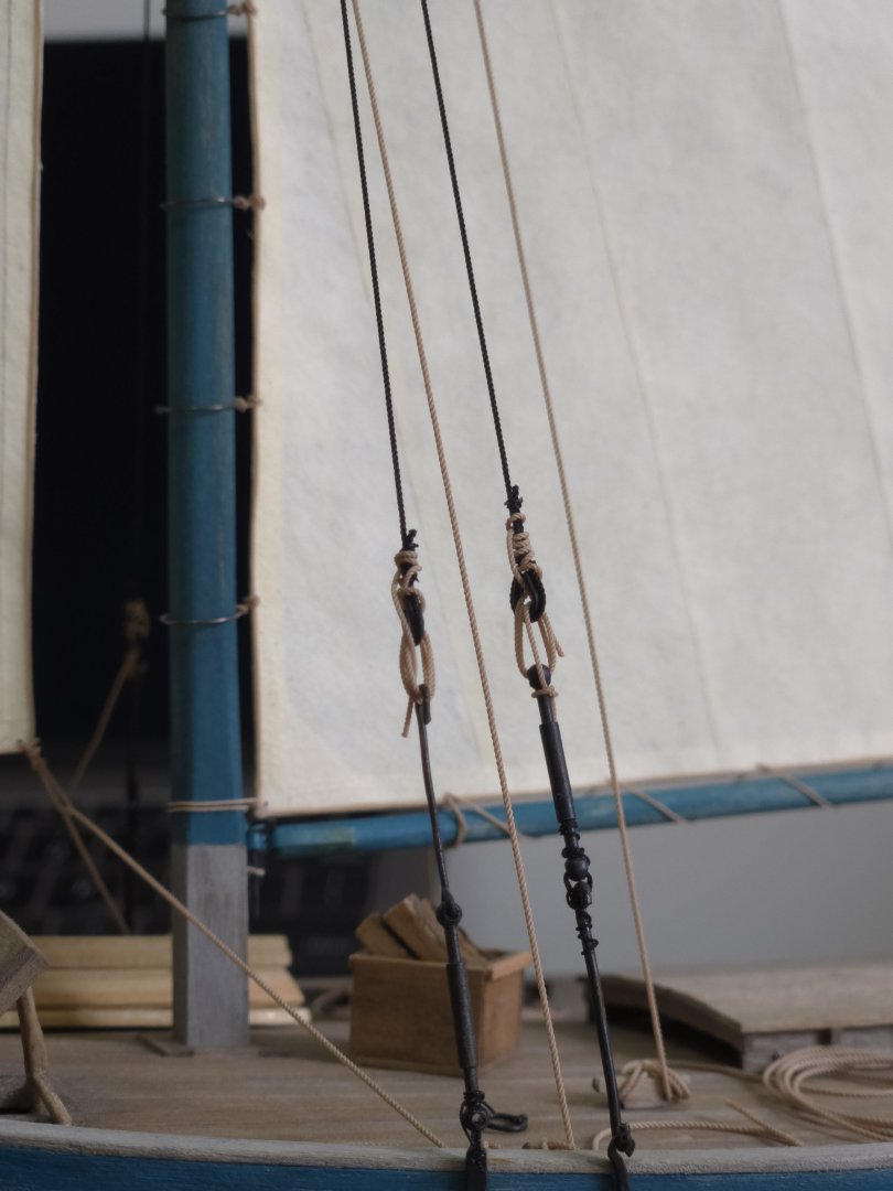
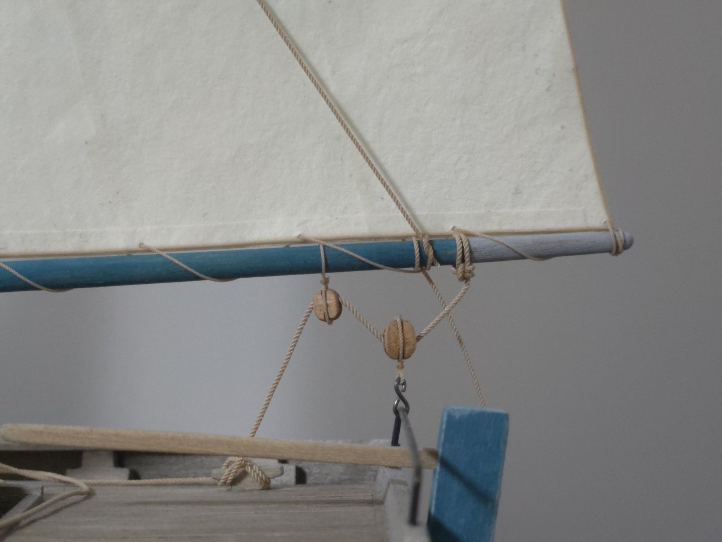
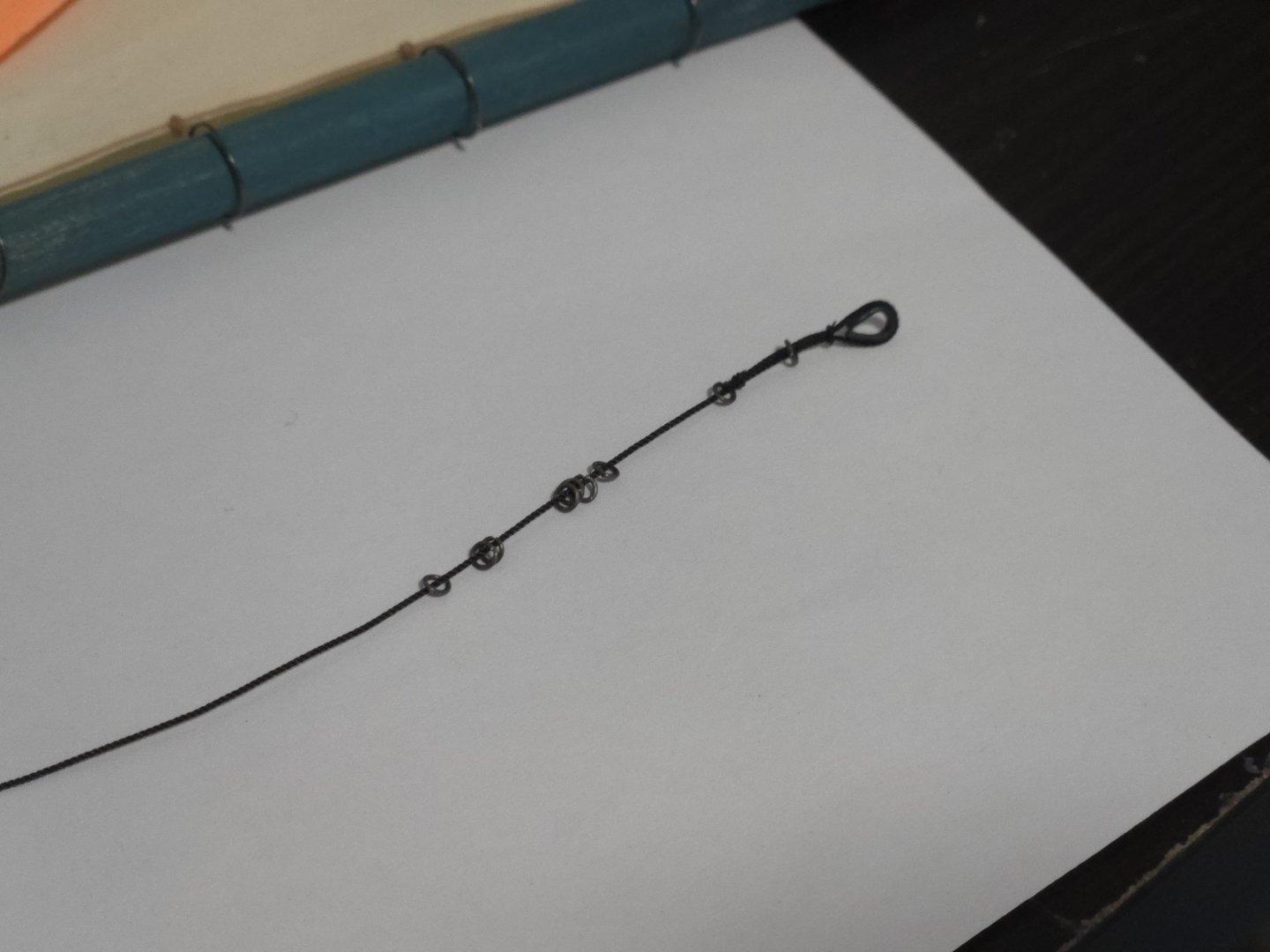
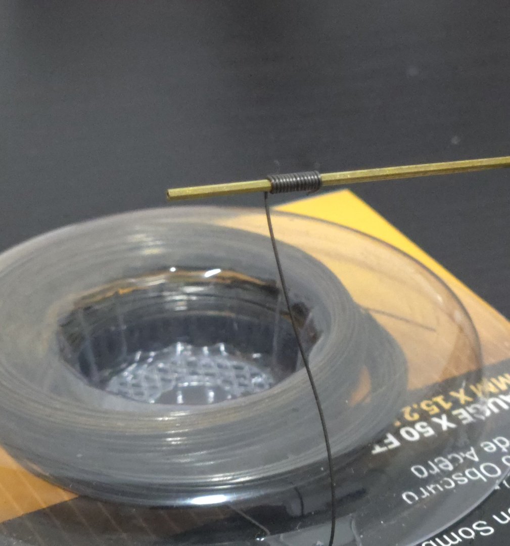
Thanks, Gary! I'm enjoying trying to make this accurate, even if the sheer variety of ways lanchas were rigged is a bit of a double-edged sword--so many ways to choose from, but at least I have choices. Satisfied with my tests, I made the hanks by wrapping 28-gauge wire around a thin brass tube. The rings are small enough (2mm across) that I could only cut off one at a time, as my wire clipper was too wide to reach any further. I made some extras in case I lose any, they're pretty tiny. To get them on the forestay, I placed them in the tip of my hemostats, used a toothpick to open them enough for the stay to fit in, and then, once they were threaded, used finger and tweezer pressure to squeeze them shut, securing with a tiny amount of superglue applied from a toothpick that I whittled into a thin point. Next up I'll need to add the lacings, and then the sail itself. Before adding the jib, though, I wanted to add the jib halyard, as I thought the seizings, in particular, would be hard to apply once the jib was on the stay. With that added, I figured that I may as well add the other halyards. I tied off the peak halyard not at the tip of the gaff spare, where many lanchas tied it off, but a little further in, so as not to put too much pressure on the spar extension. While I use half hitches for a lot, I knew I needed a different knot here, and ultimately went with a fisherman's bend, which turned out well with the .5mm rope. Adding the throat halyard, which had been made earlier in the process, was a simple step. I wasn't sure whether the gaff halyards should both be on the same side of the mast or on different sides, so I watched a documentary on YouTube about a Lancha regatta in the 1980s ("Regata a un ventisquero," Dir. Domingo Garrido, 1983: https://www.youtube.com/watch?v=CDeTRT64kd8 ) and found, arou d 1:48-1:50, that they were on opposite sides. This was helpful for figuring out how the ropes should run through the double blocks. I'm now having a bit of trouble figuring out how to do the sheet and lifts, though. My impression from photos was that either all the running rigging used the same size rope, or the sheet might use thicker rope and/or the lifts might be thinner. So, to create more visual interest than doing everything with .5mm rope like the halyards, I thought I would do the sheet in .6mm rope, and the lifts in .45mm rope. I attached the sheet with a fisherman's bend again but thought it looked very bulky, and I'm not sure if the .45mm rope for the lifts looks very thin (and makes the bulky knot stand out even more). I'm debating replacing the sheet with. 5mm rope, or using .5mm instead of .45mm for the lifts. In the photo below, the sheet in .6mm rope is at top, then there's .5mm rope, then .45mm (while the lacing is .35mm).

- 312 replies
-
- 6
-
-
- Chile
- Latin America
- (and 6 more)
-
Looks like an interesting project, hope you're able to get back to making sawdust soon! I'm curious what source you're using for Oneida being built in New York City, as I was under the impression it was built on Lake Ontario.
-
Amazing work, it's incredible how much that looks like metal!
-
Nice repair work!
-
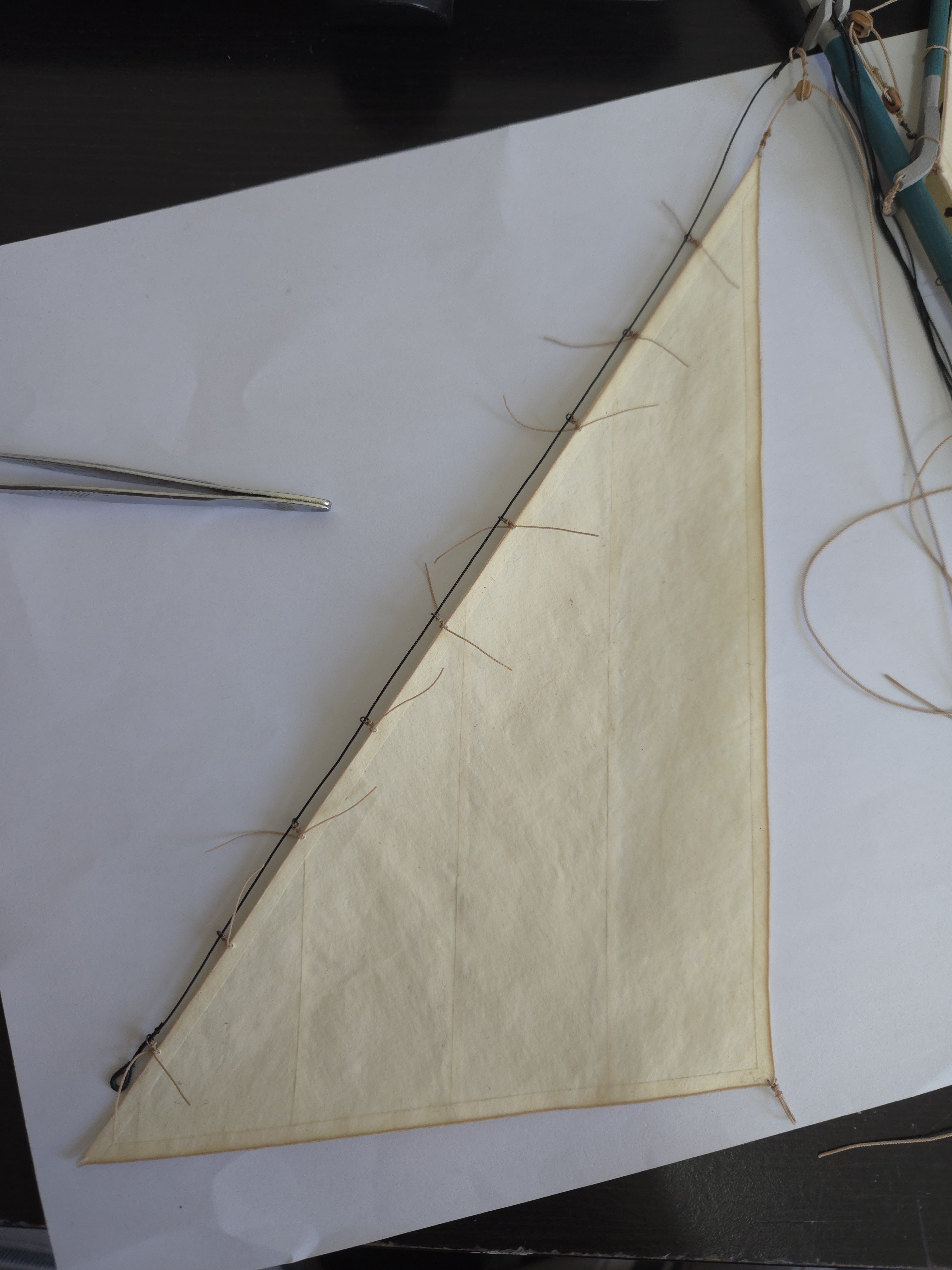
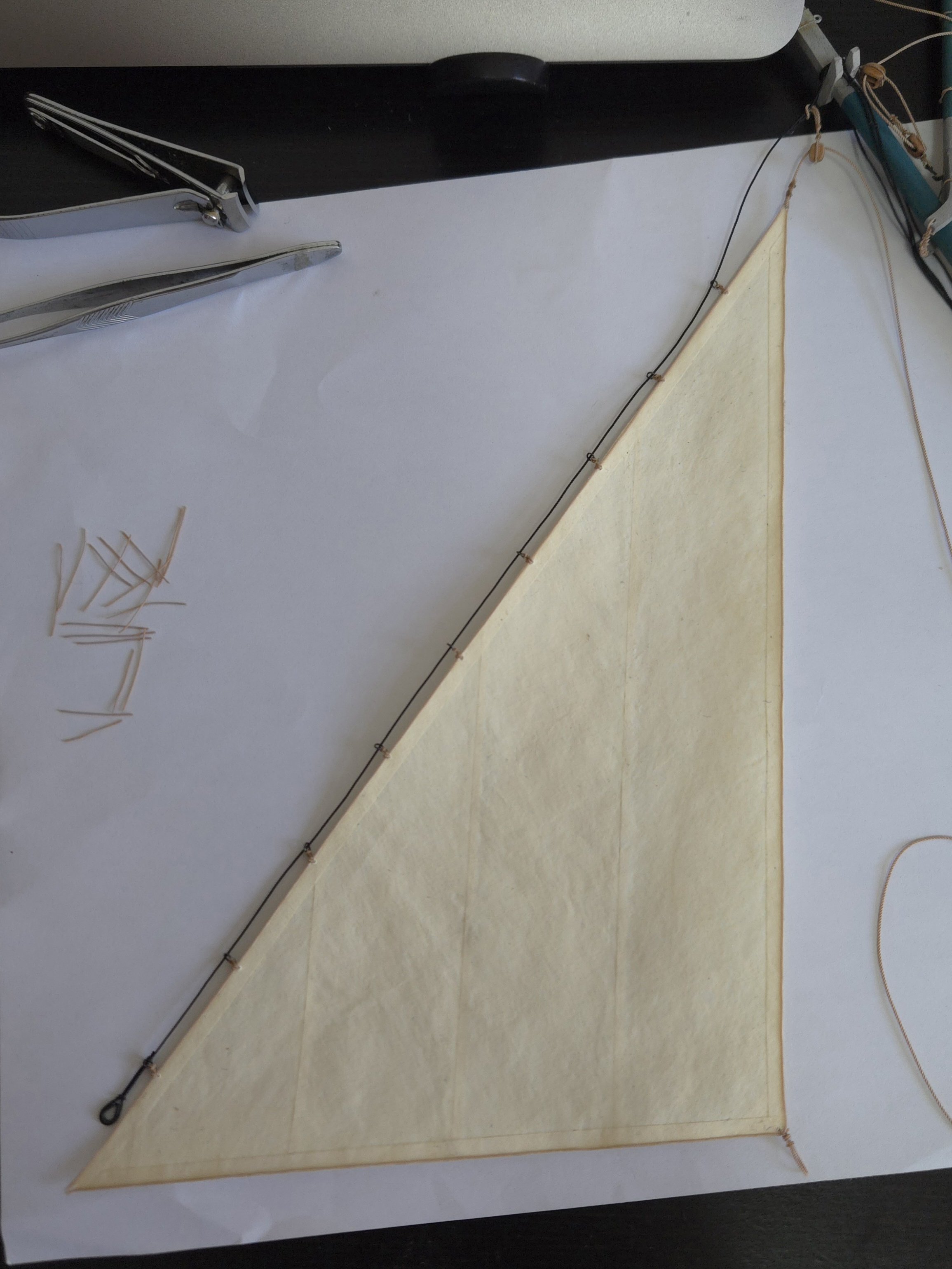
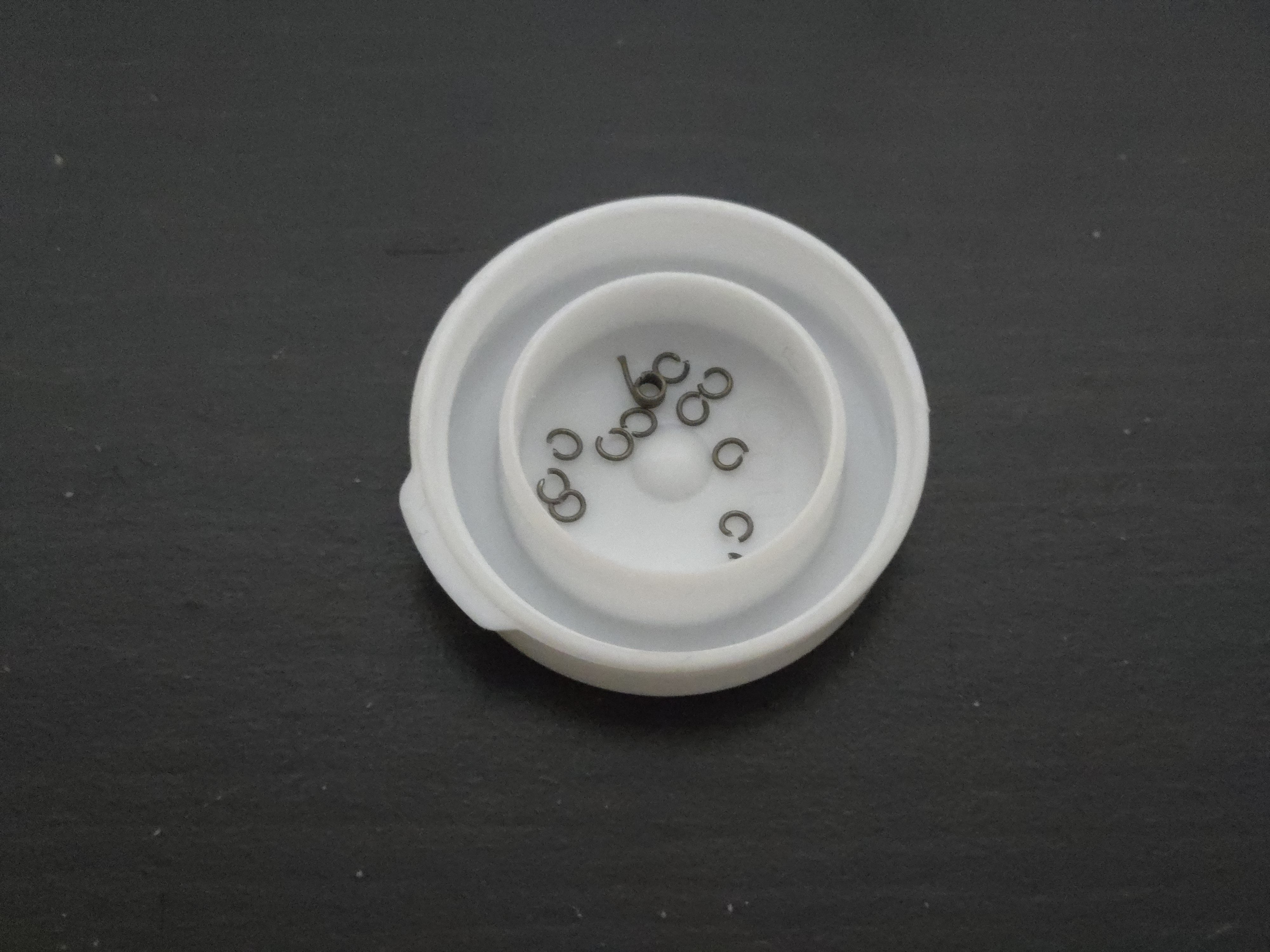
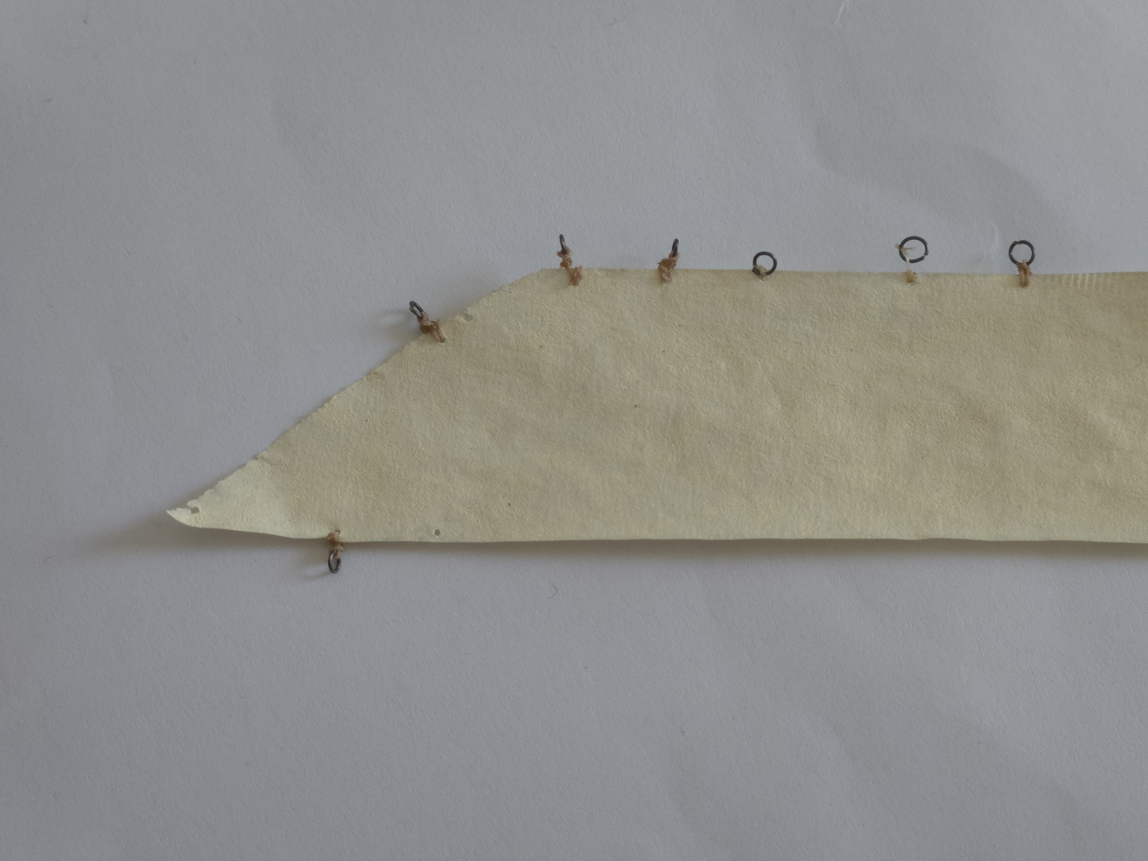
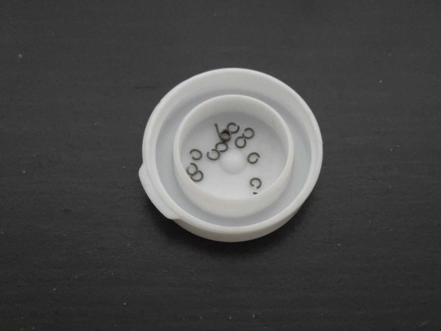
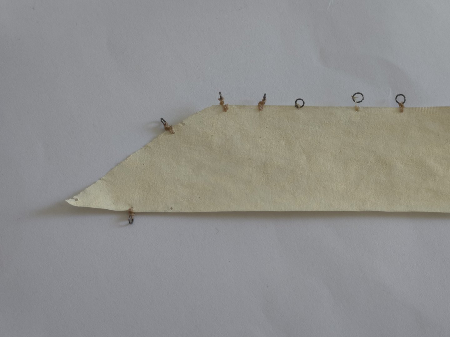
Thanks! A little more testing, and I think I have the jib hanks figured out. I can get the rings down to an inner diameter of about 1/16-inch, which is still probably slightly oversized but any smaller and I'd have a very hard time working with them (it's already hard enough even just to get my metal cutters into the ring to cut them). I also switched to using the same method I used on the mast hoops to lace them to the sail, entailing first attaching the rope to the ring and then tying on the sail. This holds the ring perpendicular to the sail instead of parallel. It took a few practice runs to get it right, as seen below: The three tries at top right were either a little bulky, or, in the case of the one on the corner, I added a little too much super glue to the initial knot and the rope became too stiff to be run through the eyelet properly, instead holding the ring too far out from the edge of the sail. The test at bottom left is where it finally came together. All of these tests, except for the early ones that used only fly-tying thread, used the cut-off bits of .35mm rope from the gaff robands and mast hoop lacing. These were tiny scraps, about 1 inch long, making it very hard to tie the knots. For the final version, I think I can go with lengths of rope about 1.75 inches long, which should be much easier to work with, without quite using all of my available. 35mm rope, as I'd like to keep a little as backup in case something needs to be redone. I think the hanks would probably look better with .25mm rope, but I don't have any, so these will have to do.
- 312 replies
-
- 7
-
-
- Chile
- Latin America
- (and 6 more)
-
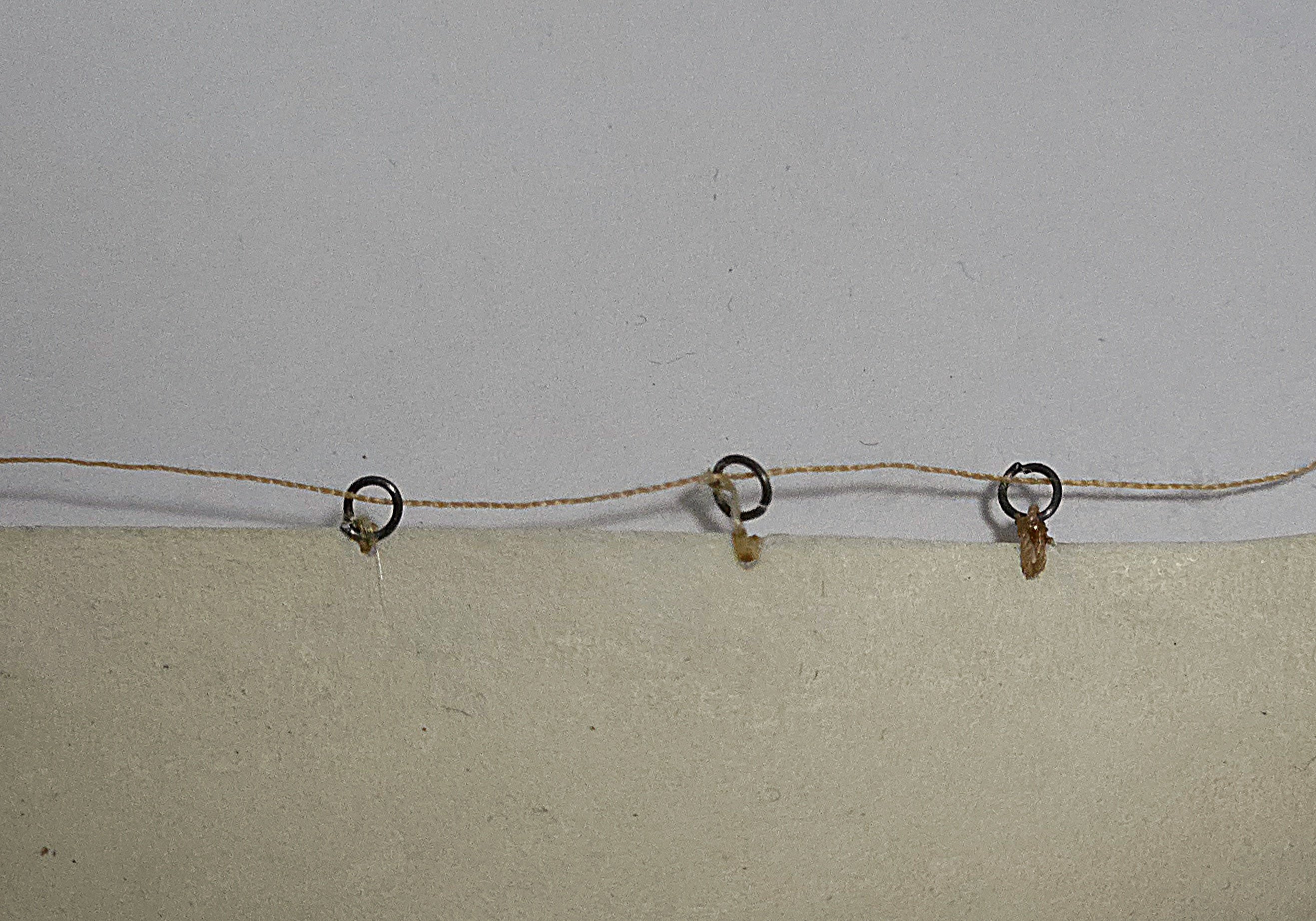
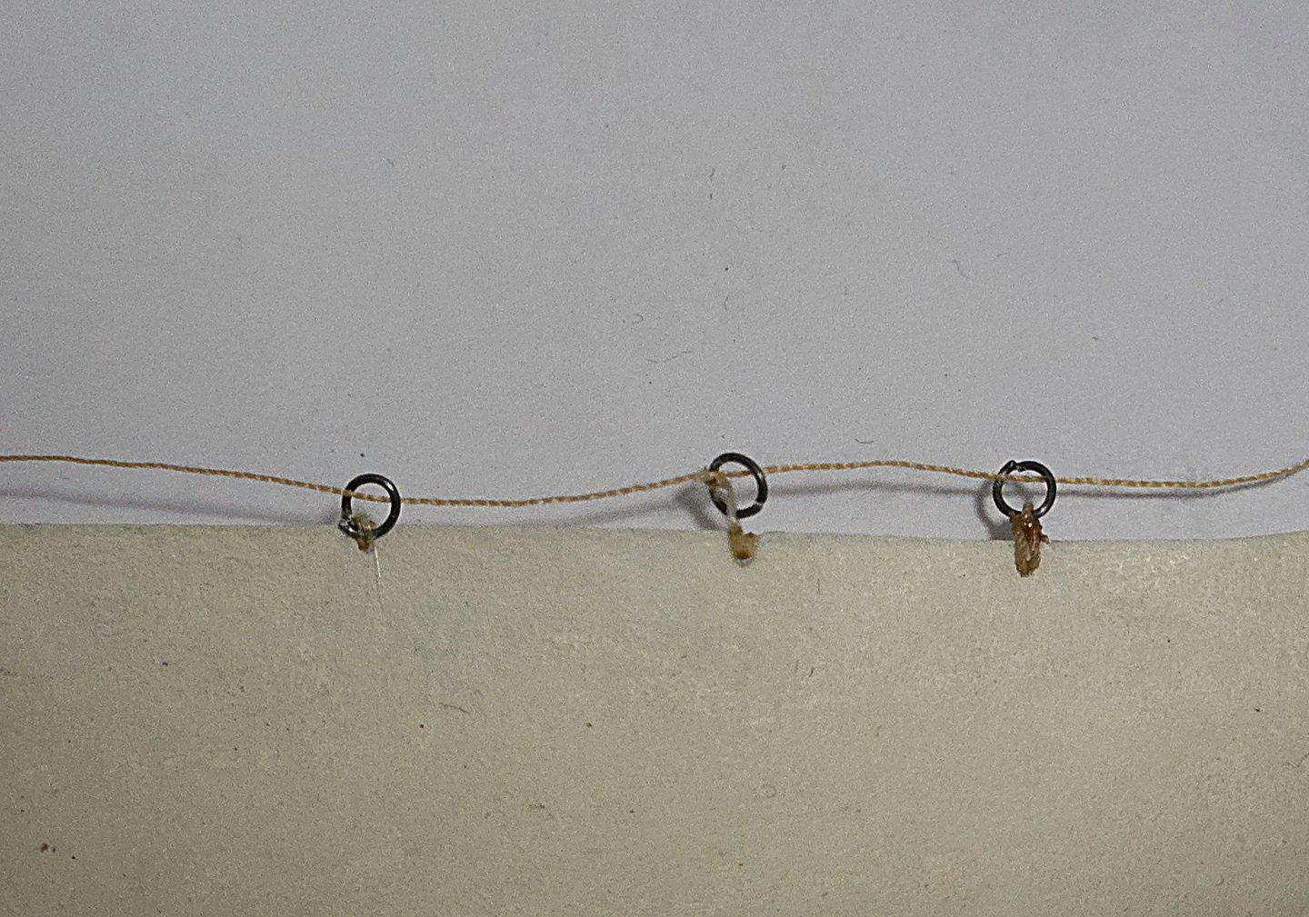
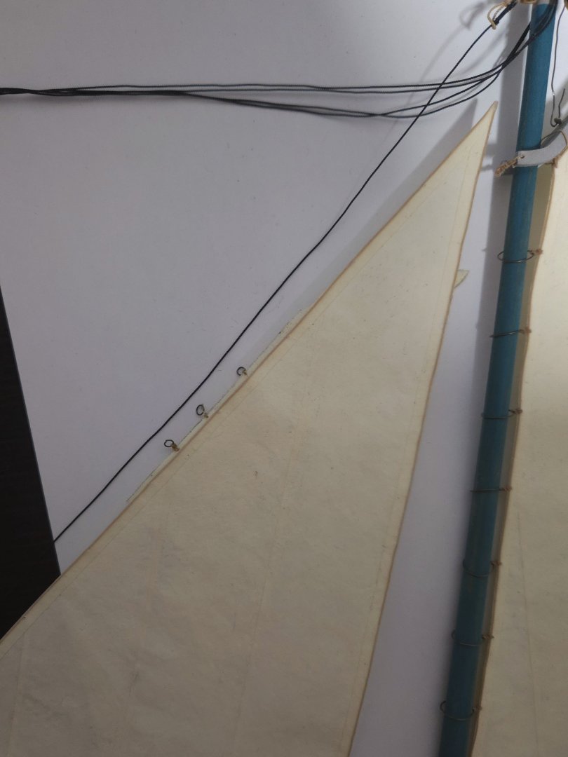
I've done a little bit of testing for the hanks. I made some small rings with 28-gauge wire and tried a few methods of attaching them. Below, there are three samples. The center one was the first I made, using fly-tying thread that I looped and tied through the sail eyelet a few times before tying on the ring. It didn't turn out very well, with the final knot barely holding on thanks only to superglue. The left example also uses fly-tying thread, but this time I only passed it through the eyelet once before looping it through the ring, and then going back through the eyelet a bit before tying it off. It turned out better, but 1) I need more distance between the ring and the sail, and 2) the thread snagged on who knows what and created a tangled bunch of fibers. I find this happens fairly often when I try to use fly-tying thread. Finally, the one on the right used a bit of the .35mm rope, secured with a couple knots and a lashing with the fly-tying thread. I think this one turned out best, although it was also the most complex to make. That said, my sense is that the metal ring is still too big. You can compare what the current size would look like on the jib, below (I tucked the test behind the jib), with some photographic examples that generally show quite small hanks. Source: https://www.bibliotecanacionaldigital.gob.cl/bnd/629/w3-article-320749.html Source: https://www.carlosvairo.com/galeria-puerto-montt-lanchas-chilotas Source: https://www.memoriasdelsigloxx.cl/601/w3-article-86076.html I'm not sure if the best solution is to keep going the way I've been going, but to make the rings a bit smaller, or to use black rope to represent the hanks instead, as it would produce a smaller hank.

- 312 replies
-
- 7
-
-
- Chile
- Latin America
- (and 6 more)
-
Very impressive work!
-
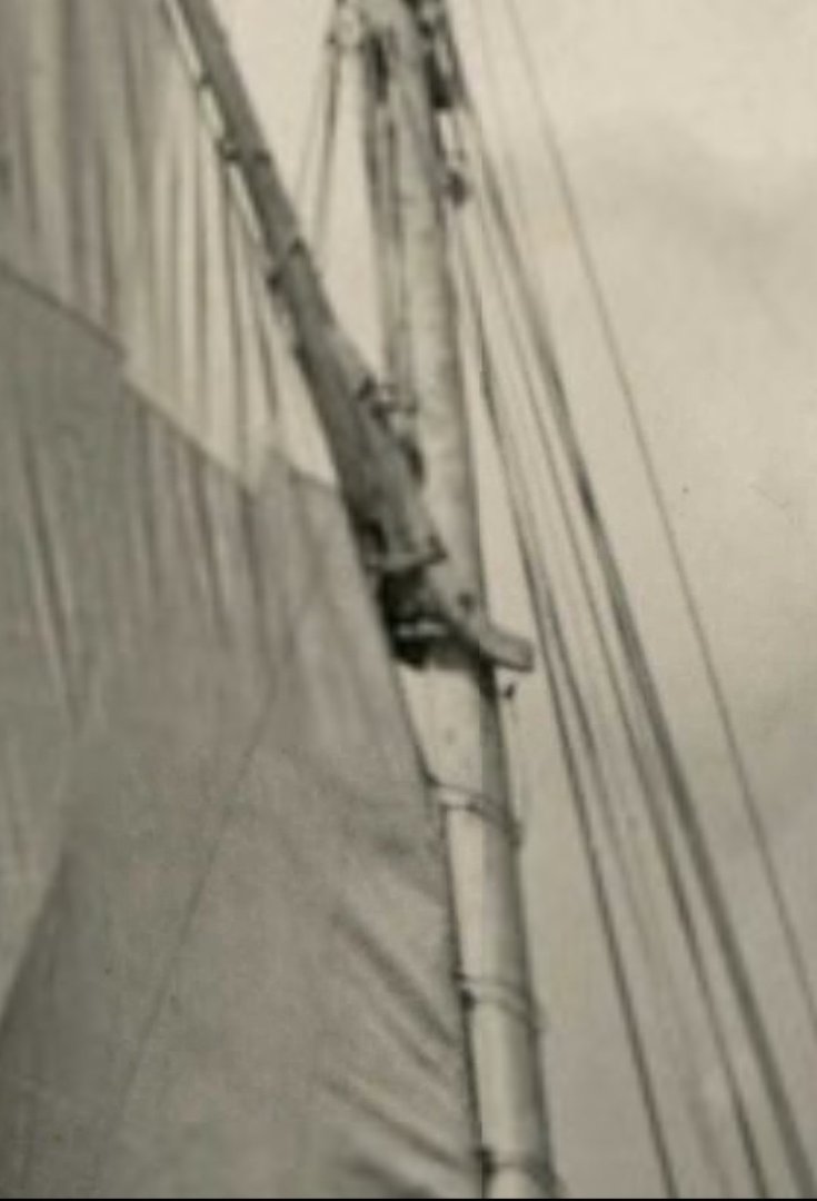
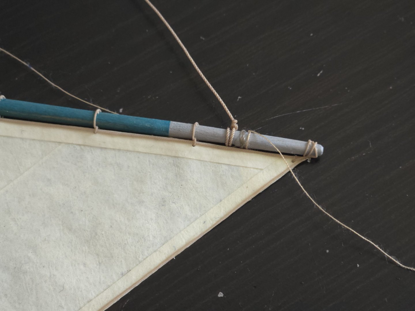
Continuing on the sail, I first laced it to the mast hoops, securing all the knots with a dab of superglue. The photo below is from before trimming the loose ends. Next, the robands on the gaff. I was initially going to just loop the rope through the eyelet in the sail and then directly around the gaff, as below. But, looking at photos, I decided it would look more accurate to first do a half hitch through the eyelet around the boltrope, and then around the gaff, as below. Subtle, but worth it. As with the mast hoops, I first tied off everything around the sail before attaching the gaff spar. The throat took some thought, as I wasn't sure whether it should be attached to the gaff or the mast, and once I decided the former, it wasn't clear how to tie it off, as it's located at the gaff jaws. After a bit of searching, I noticed in the photo below that there was a thin rope running around the gaff jaws. Source: https://www.flickr.com/photos/luchinmardones/5232587713/in/photostream/lightbox/ After seeing it in a few other photos, I now think that the throat was simply tied off around the jaws on many lanchas, so I did that, as seen below. To make the robands, I used the same "fake splice" as I've used for stropping blocks: tie a half hitch, secure with a bit of glue, and trim the ends tightly. A quick check, with the gaff temporarily held at the right angle with scrap thread and wire, to make sure none of the angles are wrong. For the boom, I ultimately decided to go with the continuous loop instead of robands. While it at first looks like the continuous loop uses more rope, that doesn't take into account that each roband needs excess rope that gets trimmed after tying the knot. Handling it as a continuous loop was much easier than doing separate robands. That said, while I've seen a number of photos with a continuous loop lacing on the boom, none of them show that on the gaff spar, so this is accurate. Finally, the photo below shows that, unlike the rest of the mast where hoops were used, the tack was held in place with a wrapping of rope. Source: https://www.carlosvairo.com/galeria-puerto-montt-lanchas-chilotas This was a pretty straightforward matter to represent. With that, the gaff sail itself is finished! Next up, I need to figure out how to properly represent the hanks on the jib, and add the running rigging. At this point, I have about 1.5 feet of the .35mm rigging left, hopefully I won't need much for the jib.


- 312 replies
-
- 9
-
-
- Chile
- Latin America
- (and 6 more)
-
That's unfortunate. Plywood does have a tendency to delaminate when soaked. If you can trace the shape of the bulwarks onto thin wood, like basswood (walnut might work too, if you already ordered it, but it will be harder to bend), you might be able to redo the bulwarks. You also might want to look at build logs for kits from Vanguard Models, I believe that company uses plywood for the bulwarks too.
-
Thanks, @Glen McGuire! I agree, I think the second option looks less bulky. Thanks, @wefalck, it's good to know that robands and continuous lacing can be mixed. While it would make a lot of sense to leave the foot of the gaff sail loose, photos show it was attached. Below, the looped continuous lacing is very clearly shown: Source: https://www.carlosvairo.com/galeria-puerto-montt-lanchas-chilotas Of course, that photo's from the early 1980s, so I wanted to check earlier photos as well. The photo below is from 1940 and shows what look to me like robands: Source: https://www.bibliotecanacionaldigital.gob.cl/bnd/629/w3-article-613541.html At this point, I'm leaning toward robands on both gaff and boom, as I think it might use less of my dwindling supply of .35mm rope.


- 312 replies
-
- 7
-
-
- Chile
- Latin America
- (and 6 more)
-
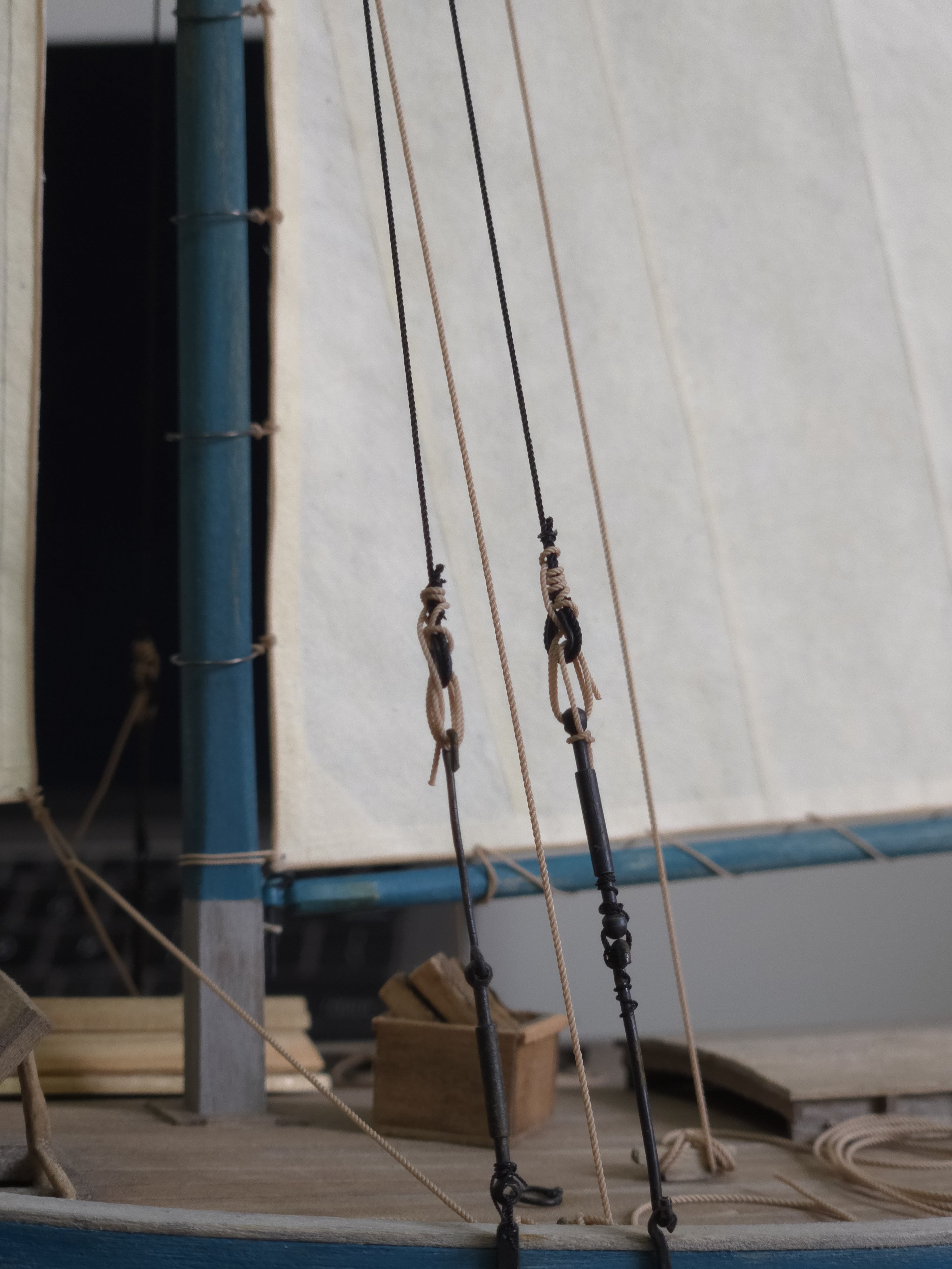
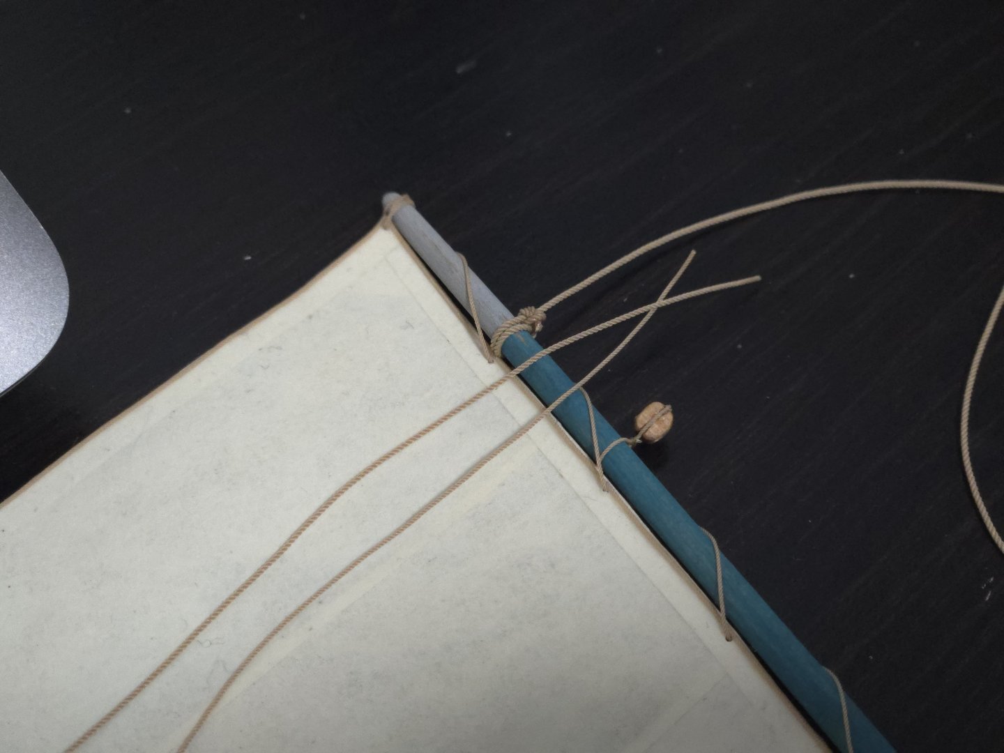
Thanks, all! Yes, Wefalck's bark technique is really excellent. If anyone gives it a try, my main advice is to not judge it until it's dry, as it looks odd and fuzzy when the paint is still wet but really sharpens up once it dries. I've continued to advance on the sails. I added the bolt rope to the gaff sail and, taking advantage of a brief break in the clouds, applied the transparent spray. I then measured and drilled holes where needed to attach the various bits of rigging. I also added a loop of rope to the clew of the jib, as photos showed that the jib sheet ran through a loop here. Next, it was time to start actually attaching the sails. After looking at several photos, I decided that thin wire mast hoops would be the most realistic-looking option. I made them out of 28-gauge wire, wrapped around a length of dowel. The dowel was a little oversized, so I trimmed a bit off the ends before gluing them shut with superglue. Next, lacing the mast hoops to the sail. A lot of other build logs show people adding the mast hoops directly to the sail and then sliding the whole thing onto the mast, which which would definitely be easier, but with everything already on my mast, this option wouldn't work for me. I drew inspiration from diagrams in John Leather’s The Gaff Rig Handbook and examples in a lot of build logs to figure out how best to loop it. I experimented with using fly tying thread, but found it a bit too thin and tricky to work with as strands kept coming off it when threading it. Instead, I went with. 35mm rope. Initially, after looping it through itself around the hoop and running it through the eyelet twice (once from each side), I tied a simple knot on each side with the remaining thread, as shown below: I had a hard time getting it tight on each side, though, and was worried that it was a bit bulky. So I retried by just tying the loose ends off to each other. I'm still deciding whether the first or second option looks best--feel free to weigh in! Both are simplifications from actual practice, but completely following how it was actually done would result in a very bulky knot here. While I decide, I've been attaching the lacing to the mast hoops. Finally, I'm trying to figure out how to attach the sail to the gaff spar and boom. It's a bit tricky. I've seen some photos where the boom very clearly has a continuous rope lacing, and others where the gaff spar very clearly uses robands. So both options seem to have been used. But would a single boat combine both methods--e.g., continuous on the boom and robands on the gaff--or would it make more sense to be consistent?


- 312 replies
-
- 9
-
-
- Chile
- Latin America
- (and 6 more)
-
Incredible work! Especially making the shiplap planks, they look great!