JacquesCousteau
-
Posts
1,374 -
Joined
-
Last visited
Content Type
Profiles
Forums
Gallery
Events
Everything posted by JacquesCousteau
-
 Nice progress!
 -
Excellent work! At 1:24 scale, those 5mm work out to 12cm on the real vessel. I think you can chalk it up to building differences between shipyards.
-
Great start, looks like an interesting kit!
-
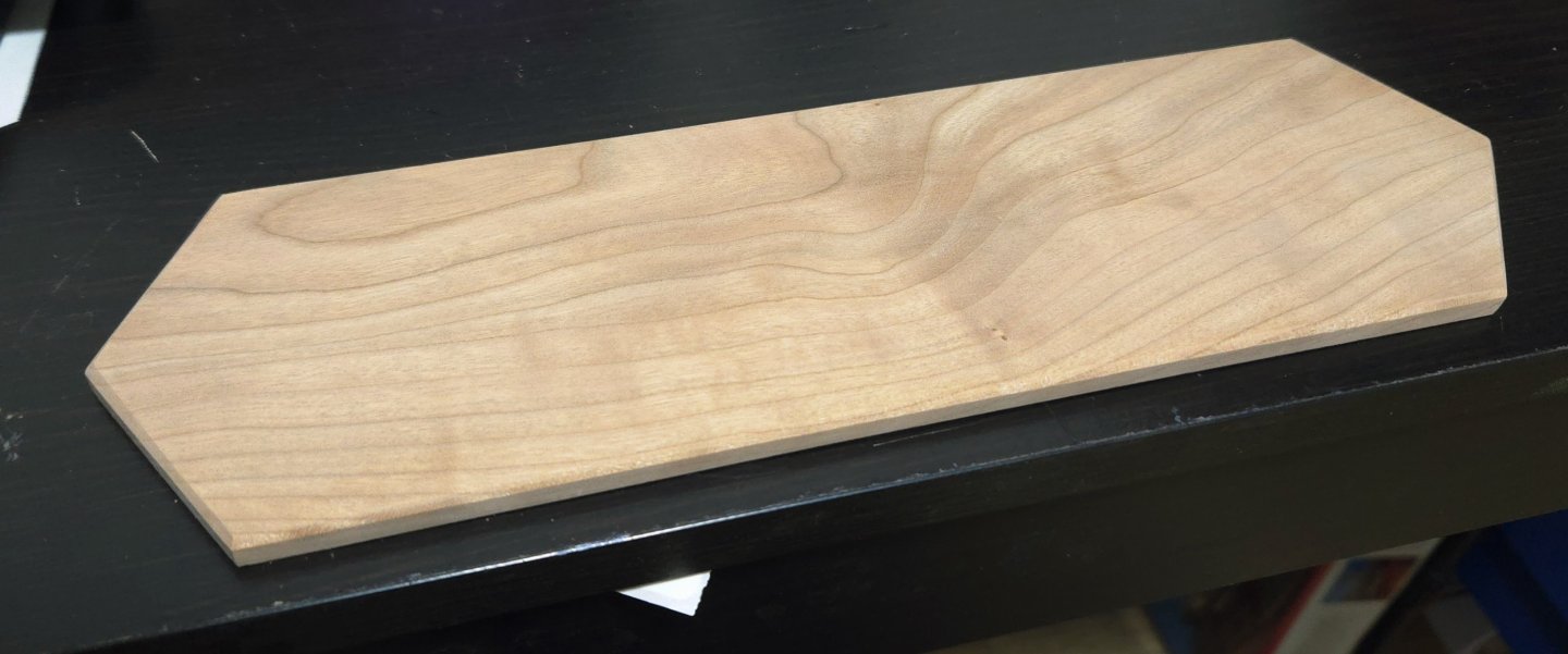
As I advance on the build, I'm also looking at finishing the base. I was very curious to see what linseed oil would look like on the cherry, as I really like how it turned out on my Half-Hull model. I also tried a bit of my very basic water-based sealer/varnish, testing both on sone scraps. Below, you can see the results compared against the still unfinished board. I was surprised. The linseed oil (at top) significantly darkened the cherry in a way that I don't love. The sealer, in contrast, at right, slightly darkened it and brought out the grain patterns a bit more. As a result, I've decided to go with the sealer/varnish on the base, allowing it to naturally darken a bit with time.

- 312 replies
-
- 7
-

-
- Chile
- Latin America
- (and 6 more)
-
Great choice for a build, I'm looking forward to following along!
- 457 replies
-
- 2
-

-
-
- sternwheeler
- Hard Coal Navy
- (and 1 more)
-
Thanks, all! Adding those with the mast stepped was definitely a challenge. Fortunately the rest will be done off-model until the final rigging.
- 312 replies
-
- 4
-
-
- Chile
- Latin America
- (and 6 more)
-
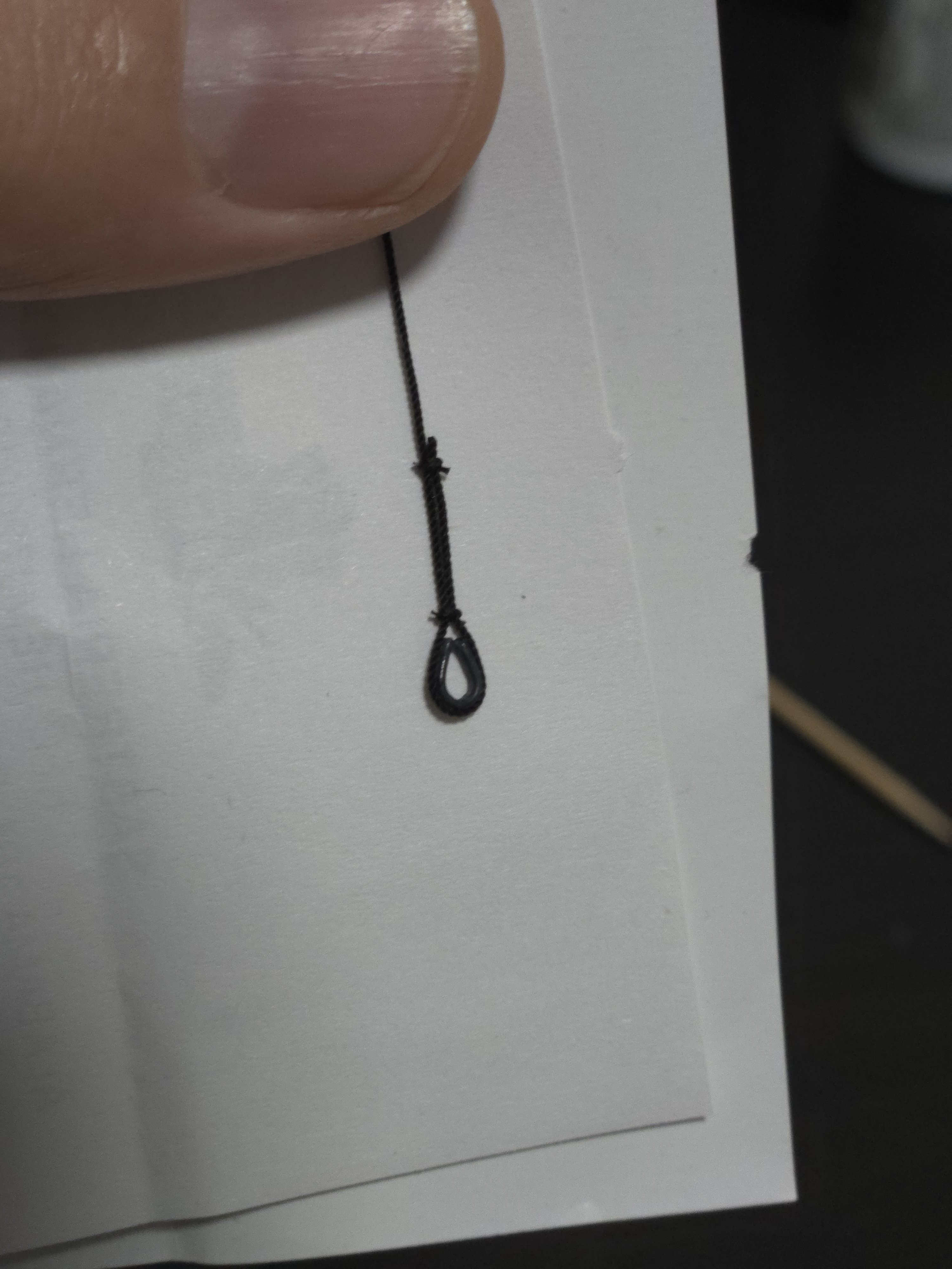
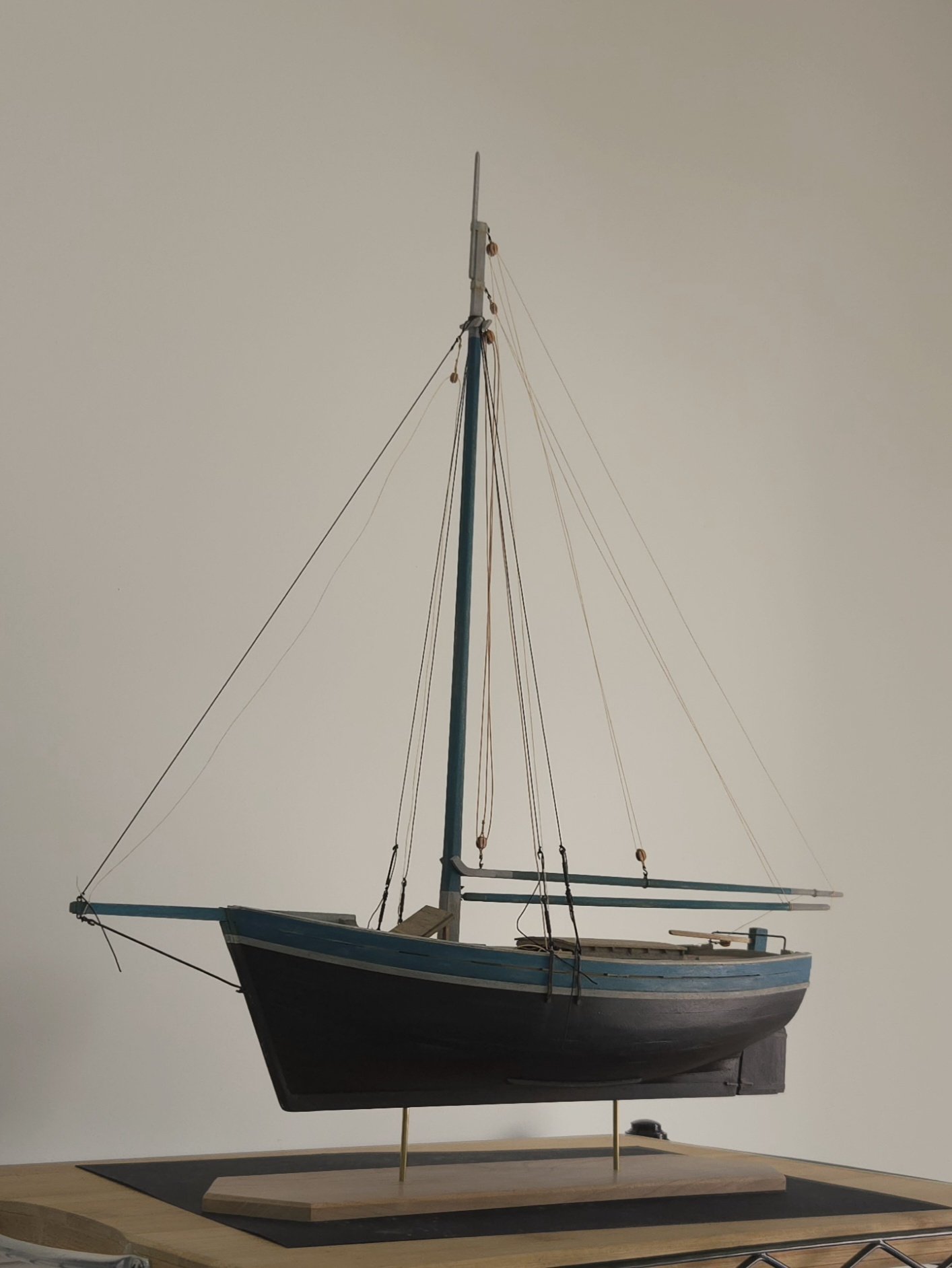
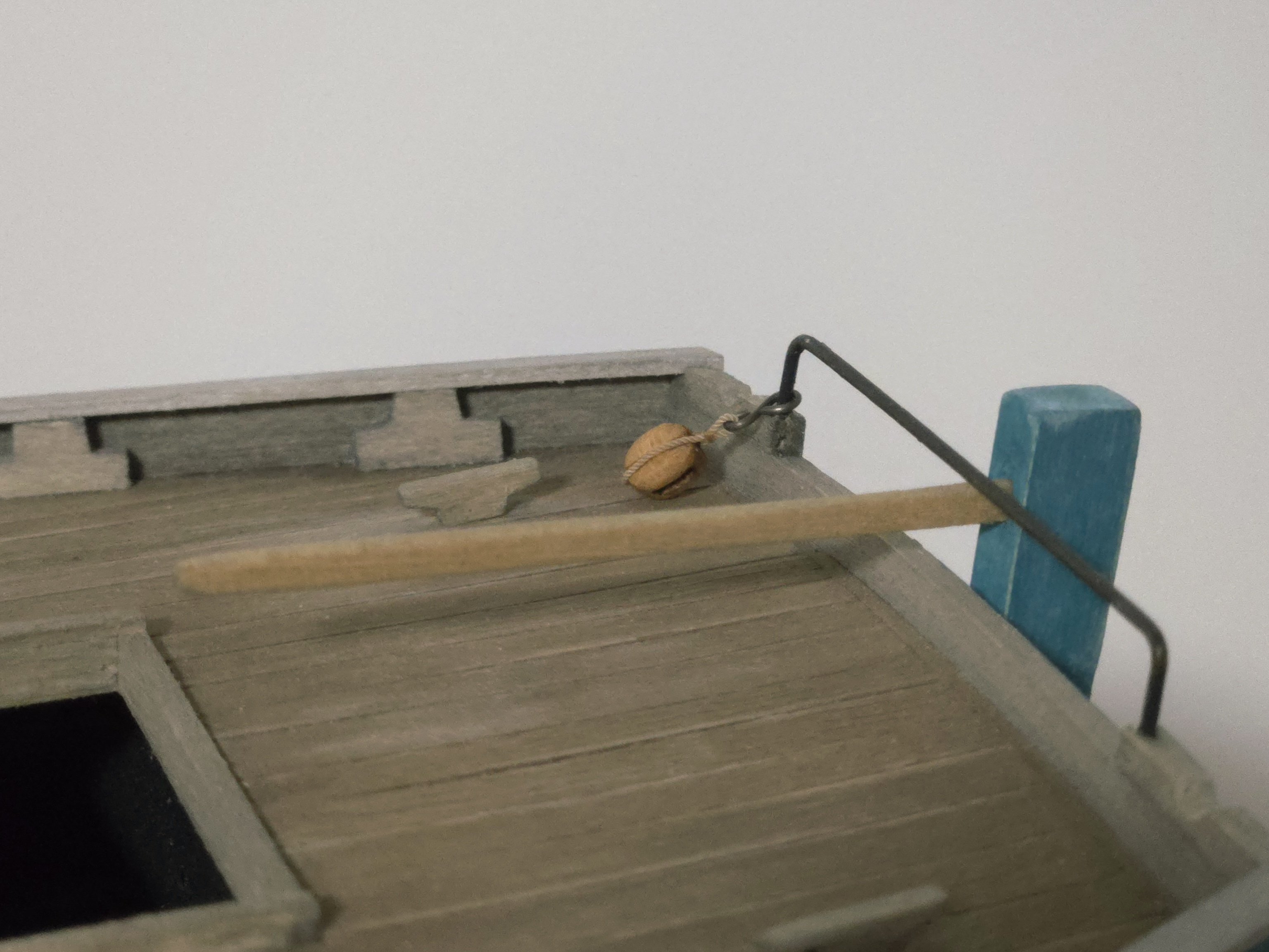
I'm inching toward the finishing line here. Next on my list: attaching the thimbles I made earlier to the shrouds and forestay. This would have been much easier with the mast off the model, but I couldn't do that because I needed everything in place to work out where on the lines the thimbles needed to be located. As everything had to be done in the air, I really couldn't take any photos mid-work. My process, after a bit of trial and error, was to figure out the approximate height, use locking tweezers to hold a small loop in the line, and then loosely tie a bit of fly-tying thread around it. Then, put a drop of superglue on the thimble, place it in the loop, and move the thread knot close to the thimble and tighten, adding a few more knots while wrapping it a bit around the line and securing with a drop of superglue. After trimming the excess, add another knot with fly-tying thread further up, and trim the excess. The forestay thimble, the first I did, is shown below. And, below, a shroud thimble before trimming the excess thread. By now, I've added all the thimbles. Next, I'll need to unstep the mast, add the final sheet block to the boom, add a parrel in the gaff jaws, and set up the mast again, this time using the correct rope for all running rigging. The end of the rigging is nearly in sight!

- 312 replies
-
- 7
-
-
- Chile
- Latin America
- (and 6 more)
-
Congratulations! This has been a fascinating build to follow along with. The techniques used, on such a small scale, have really been something else, and the final result is stunning. Really well done. The model will look excellent alongside the pile driver.
- 732 replies
-
- 4
-
-
-
- Lula
- sternwheeler
- (and 1 more)
-
Nice work on the rigging! Would it make sense to drill a shallower hole and shorten the bottom of the mast by the corresponding amount?
-
Nice work on the planking, rail, and wale! The stain may not be quite what you were hoping for, but alongside the walnut I think it makes for a nice "rustic" look that can work well for this type of relatively stylized model.
-
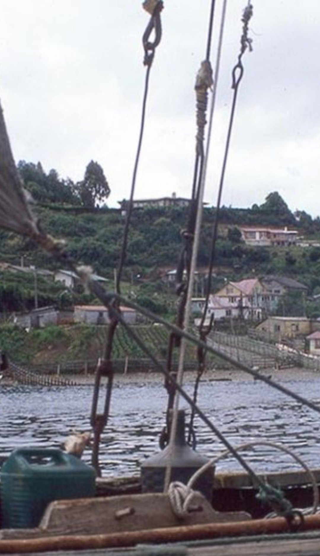
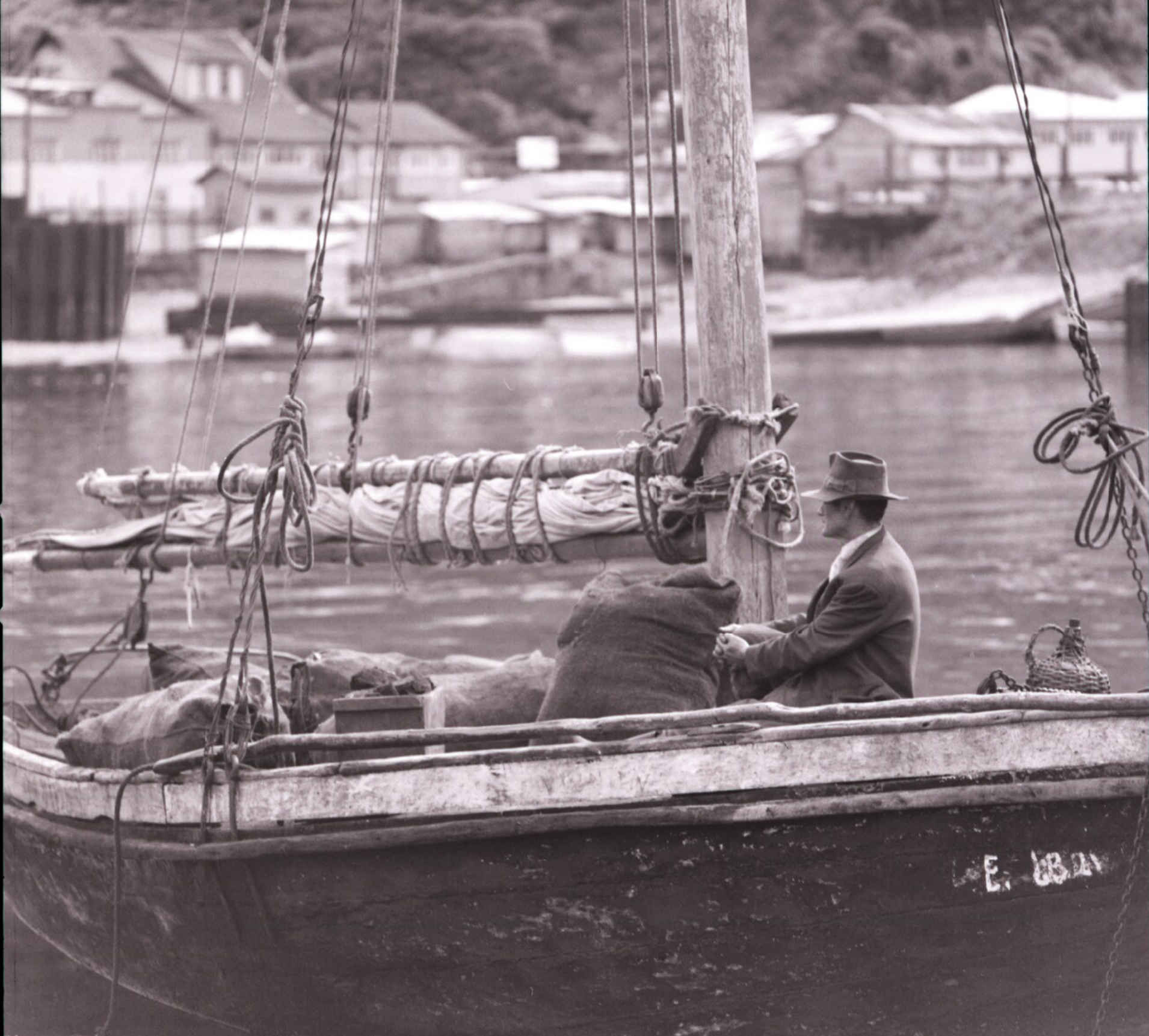
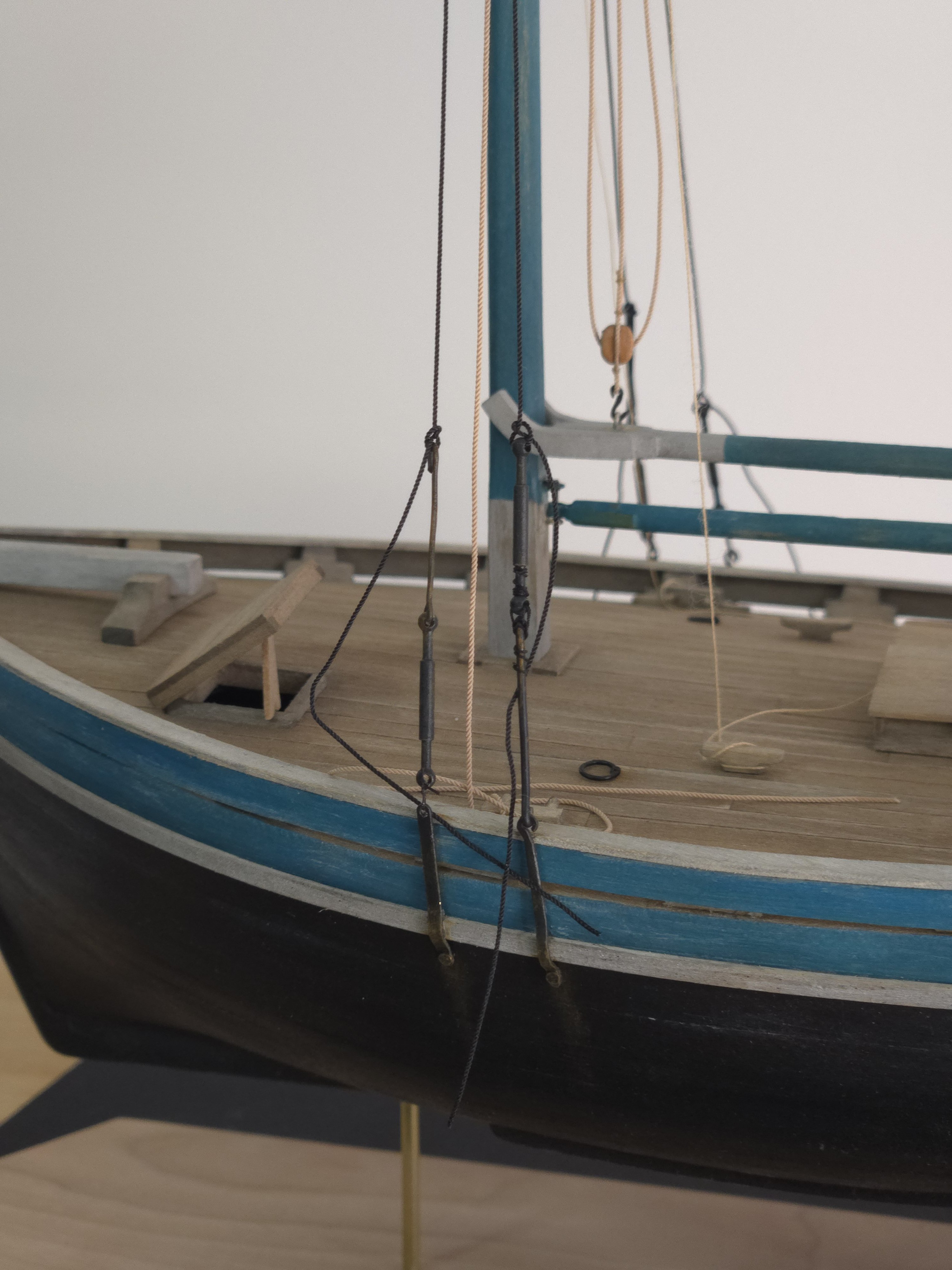
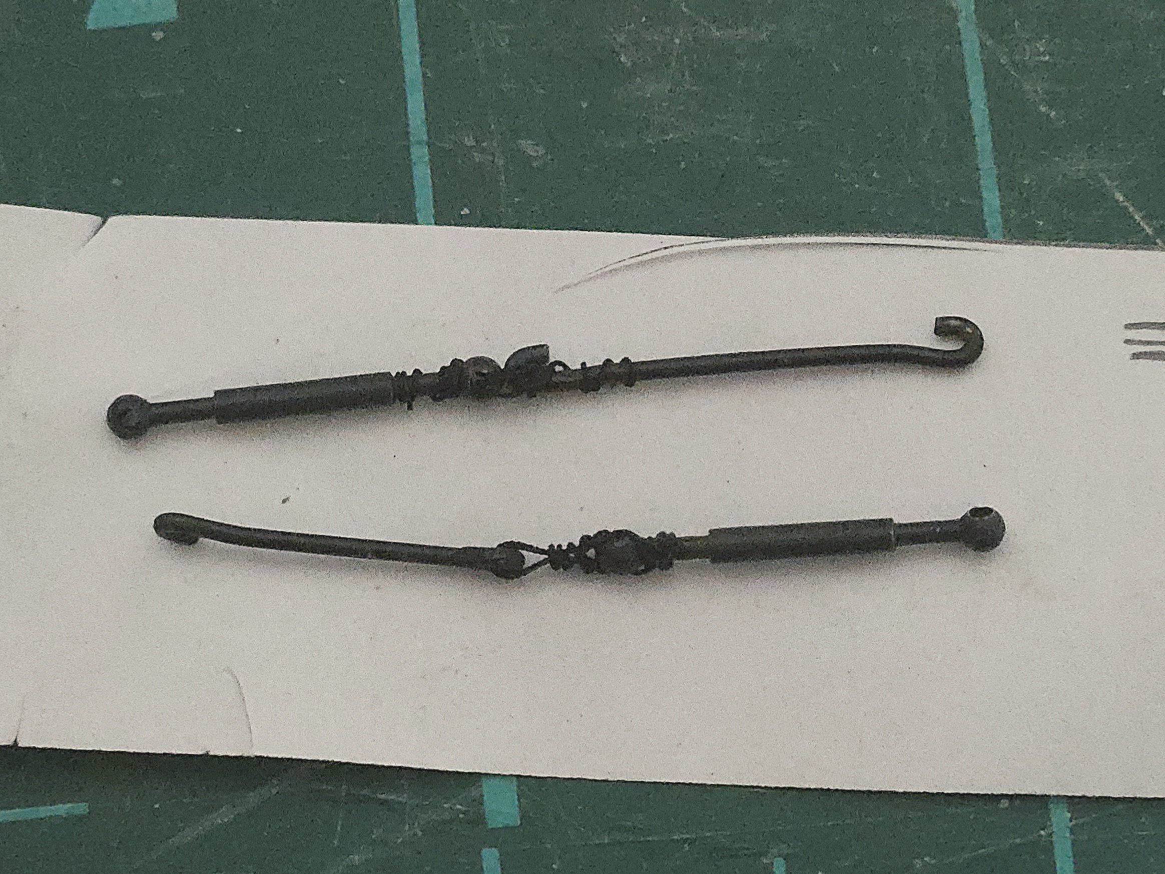
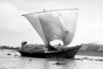
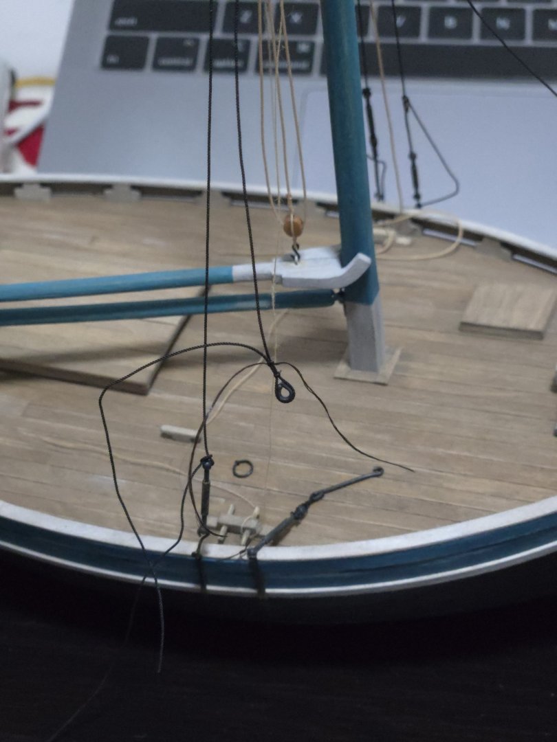
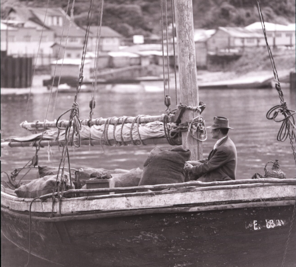
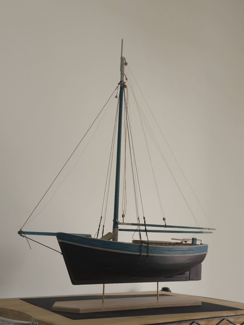
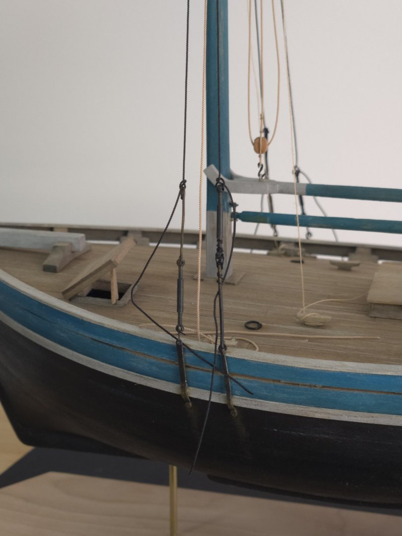
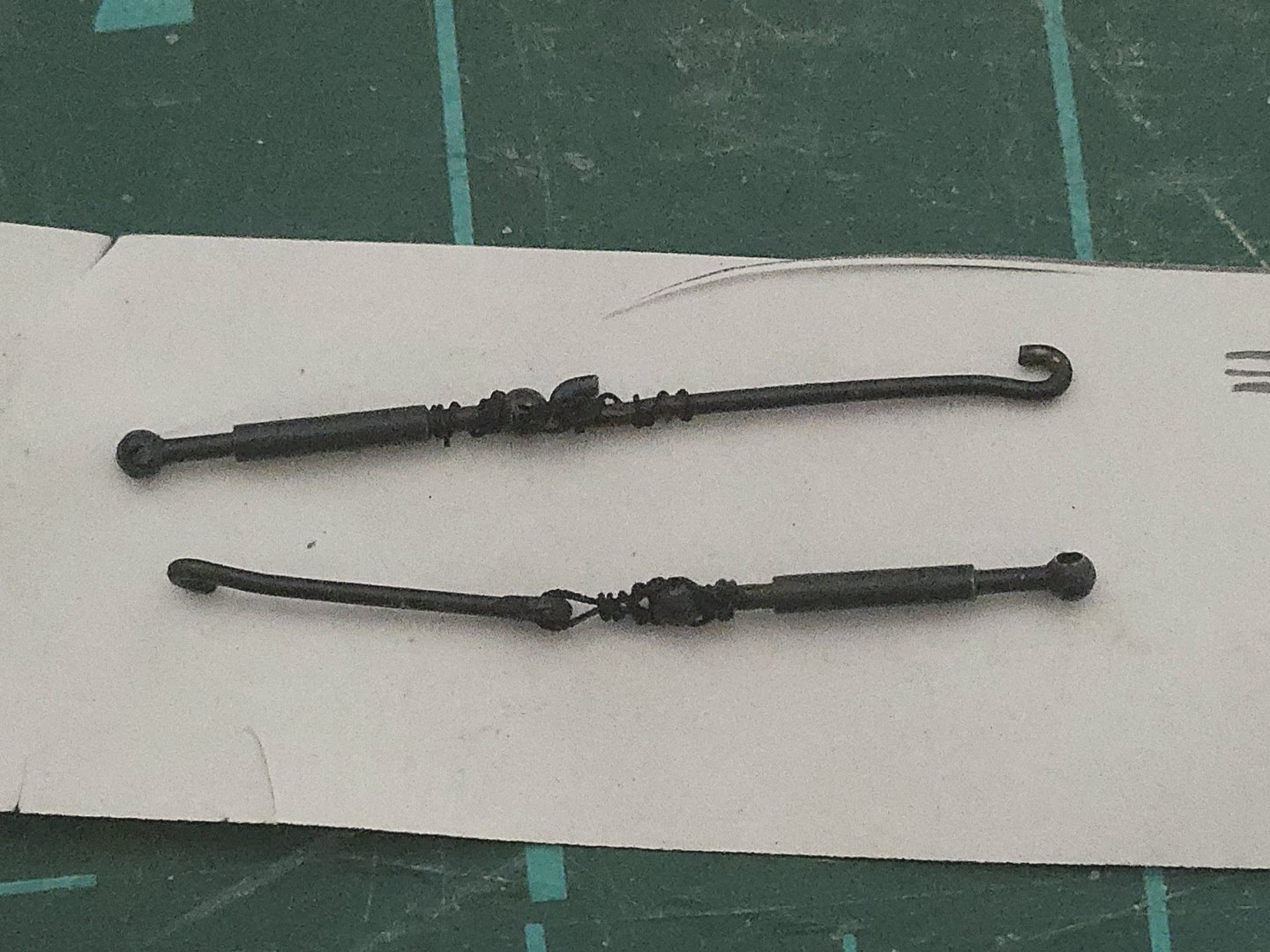
Thanks, @wefalck, I'll have to look into a nitrocellulose wood sealer. The sealer/varnish I have is water based, so I don't know if it would have the same effect. I was able to make a little progress on the turnbuckles and shroud hooks. As seen in photos like those below, these were often held together (and to the shrouds and chainplates) with rather improvised-looking lashings of wire and/or rope. Source: https://www.bibliotecanacionaldigital.gob.cl/bnd/629/w3-article-644834.html Source: https://www.carlosvairo.com/galeria-puerto-montt-lanchas-chilotas While two of my turnbuckles are directly attached to the hooks, the other two are lashed in this fashion. I used 0.25mm black rope from Ropes of Scale to represent a wire lashing, and tried to get an improvised look, with the "wire" tied off in different ways. I think the lashings turned out all right (although up close the limits of my pre-made "turnbuckles" are pretty apparent--I think that making better ones would require soldering, which is a skill I don't have). I plan on using similar wire lashings to attach these turnbuckle assemblages to the chainplates, then rope lashings to attach the tops of these snugly to the shrouds. As can be seen, there's some variation in height, which I was going for. Finally, I temporarily tied the turnbuckles to the chainplates with flt-fishig thread, slotted the mast in place, and did another test rigging. This was useful to check how the turnbuckle assemblies looked in place, as well as to practice the rigging steps--I've learned that I need to pay attention to the order in which I run the gaff halyards through the double blocks, as it impacts which side they need to be belayed on. It also helps me get a sense of how the model will look on the stand if I go without sails. I had been considering some sort of angled stand to show it as though it was beached on its guardaplayas, but I ultimately think I like the look on a brass stand better.


- 312 replies
-
- 9
-
-
- Chile
- Latin America
- (and 6 more)
-
Very big news, I'm glad to hear that you've found a way to keep the existing kits going while reducing your own workload and need for storage space! I'm looking forward to seeing what plansets or Seawatch books you come out with--I'd especially be interested in the Block Island Cowhorn, if there are any plans to get back to that model once things have gotten calmer.
-
Nice work! There are lots of ways to simulate caulking, including by rubbing a pencil along one or both edges. I'd recommend using a bit of scrap wood to test some different options and see which you like best.
-
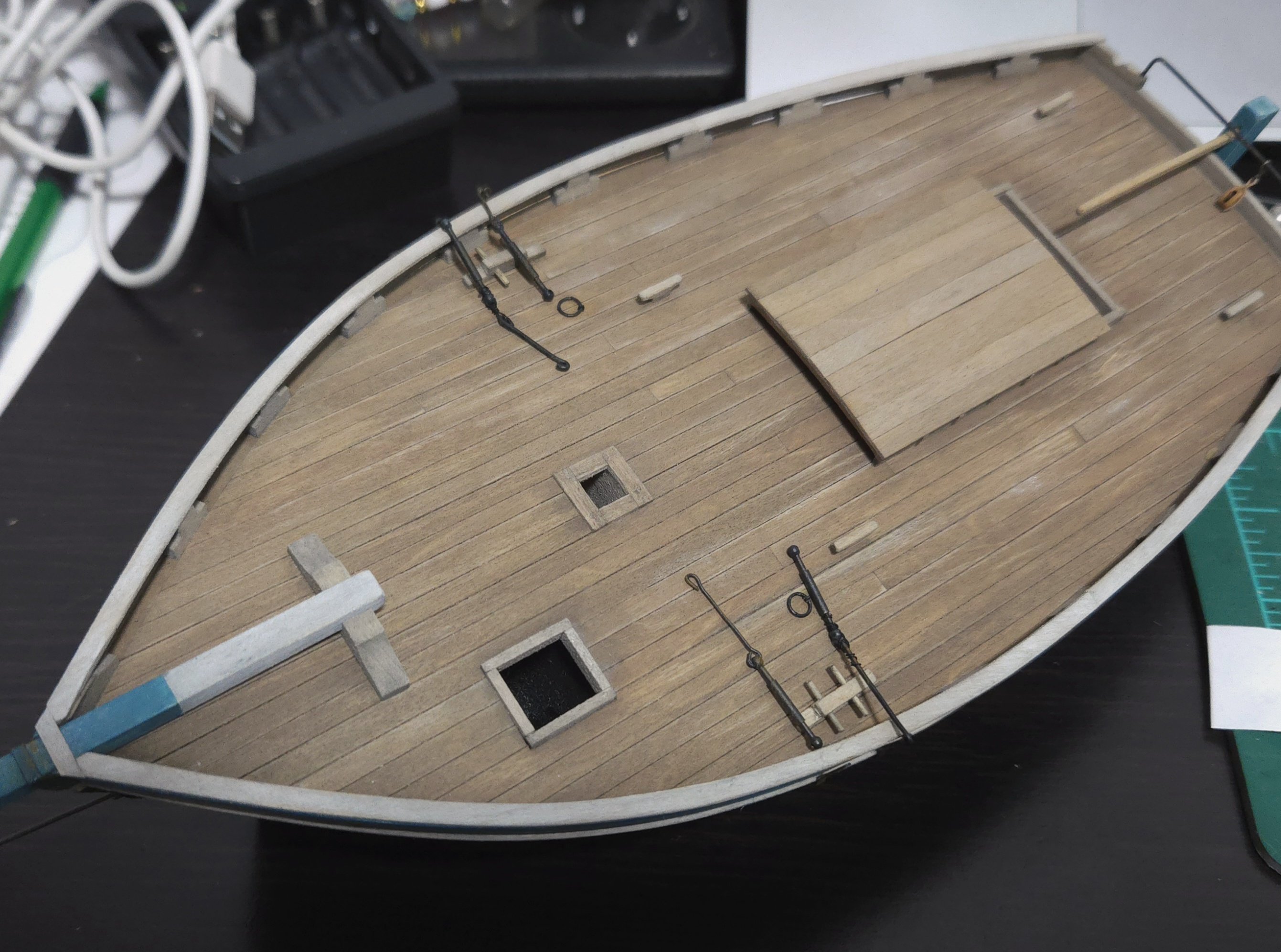
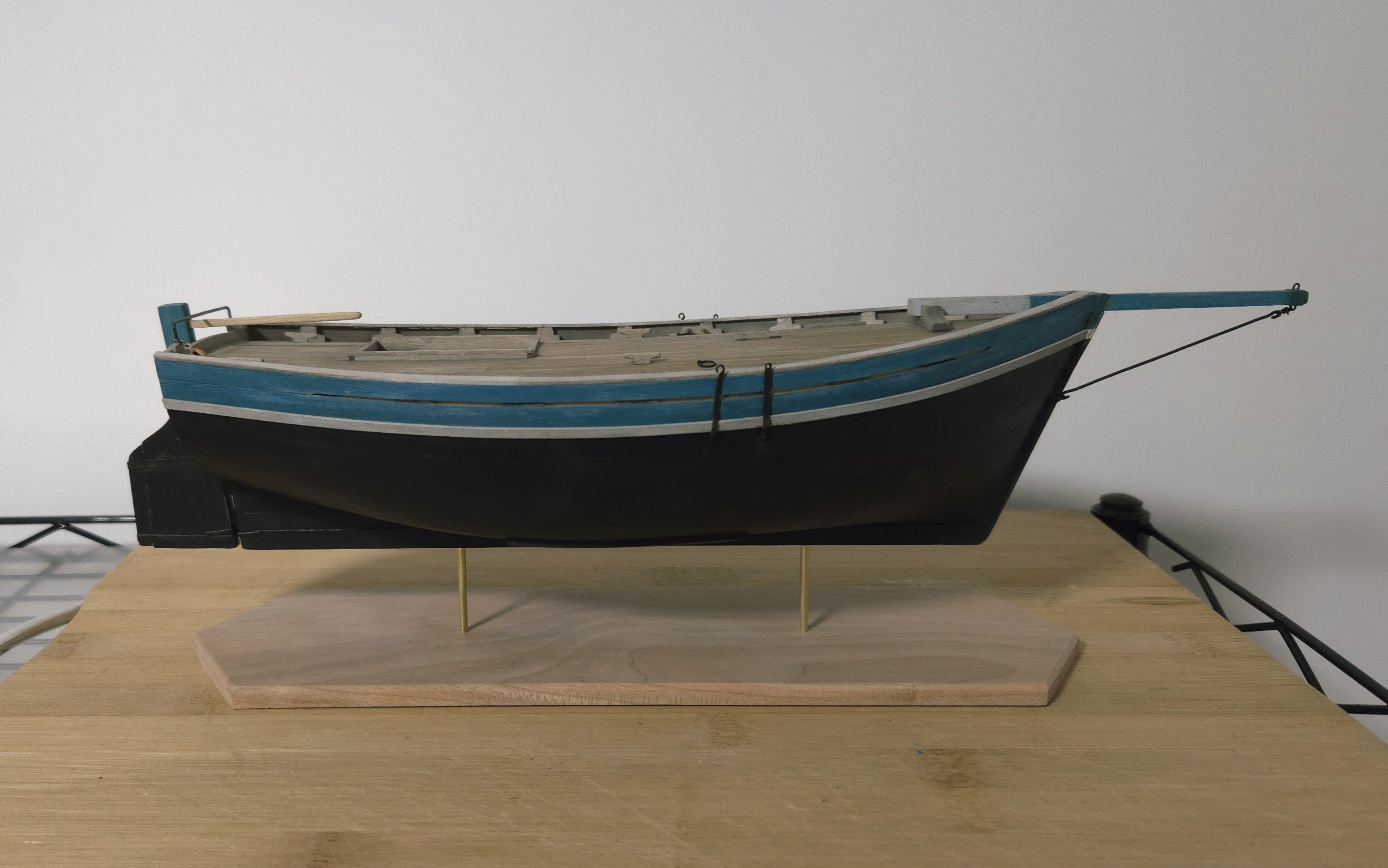
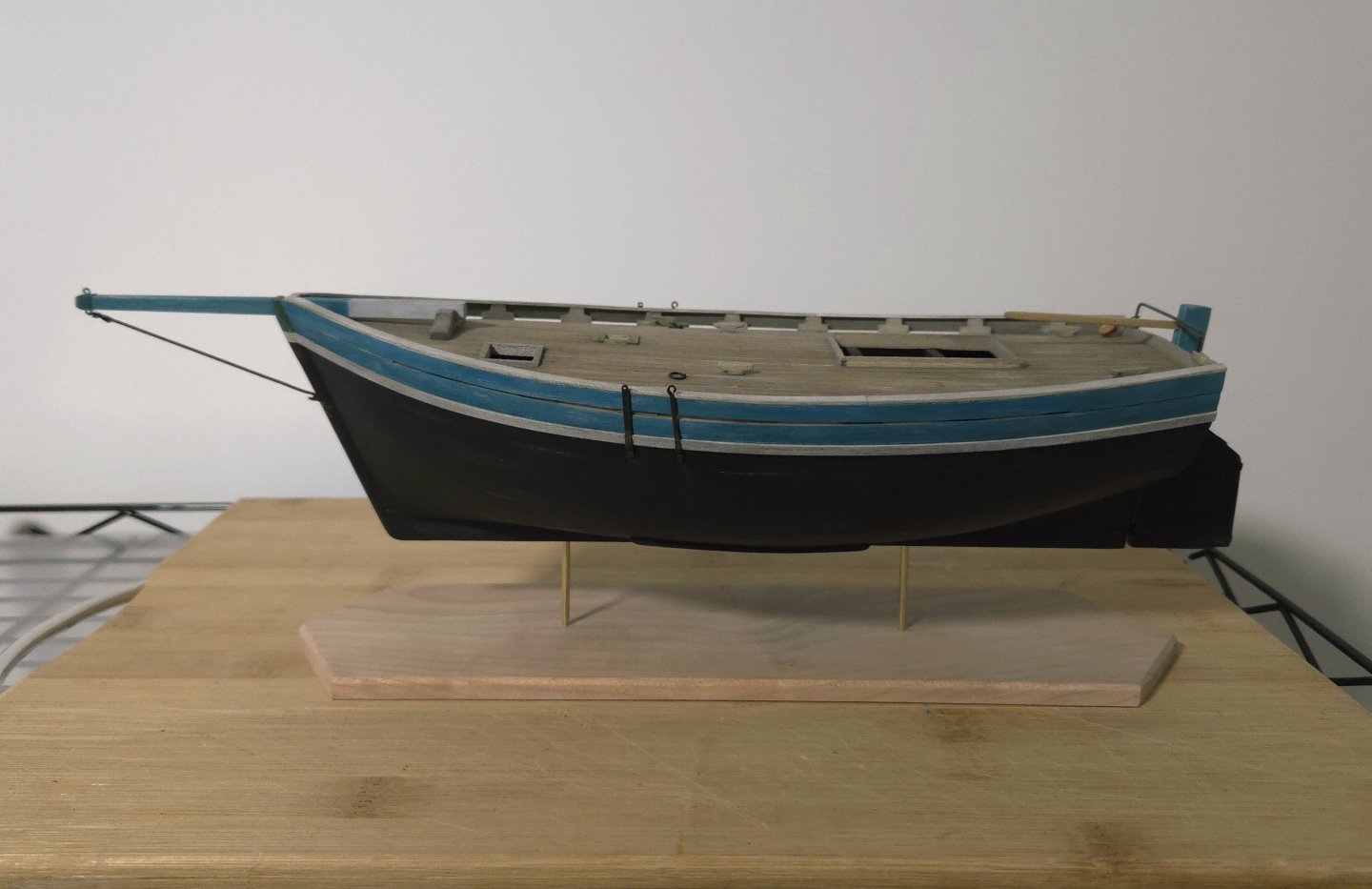
I've made a bit of progress on the rigging, painting the shroud hooks and adding the traveler block, below. For the latter, I left the hook as unpainted annealed wire, as I needed to bend it shut around the horse. The color difference doesn't stand out too much, thankfully. I also made more progress on the cherry base. After a bit more searching, I think the gouging I mentioned above may have been tear-out from where the grain direction shifted around the knot. After a lot of sanding didn't quite get rid if it, I tried to use a cabinet scraper. Despite following a lot of "how to" videos, I couldn't get a good burr on it, and it only ever produced dust instead of shavings. So, I kept sanding. Finally it seemed acceptable. At that point, I cut out the base, adding a point at each end, which I accidentally made sharper than I had planned--good reminder to measure twice, cut once! I also lightly beveled the edges with my mini plane. I then cut out the 3/32-inch brass tube supports, using my razor saw. As I didn't quite get the holes drilled perfectly in the keel, I had to add some slight bends to get the supports right. Next, I drilled the holes for the supports in the base--this time triple-checking they were properly lined up and measured before drilling. Finally, I was able to dry fit the hull. I'm pleased with how the base has turned out, although I still need to decide how to finish it--I do have some linseed oil that I'm testing on some scrap, although it will take a long time to dry. I also need to slightly adjust the bends in the brass tubes, and to think about how I want to orient the model on the base. Next up, I need to figure out the deck cargo and furnishings/fittings, and finish the rigging. On the latter, if I complete the build without sails, there's relatively little left to do--just add the mainsheet and its boom block, add the lifts and sheets, and add thimbles to the shrouds and forestay and tie them off. But, if I want sails, it will be much easier to fit them with the mast off the hull and add the mast at the very end.


- 312 replies
-
- 9
-
-
- Chile
- Latin America
- (and 6 more)
-
Excellent work, this was a very interesting and informative build. The end result looks great! I have to ask: how big is the complete model? 1:87 scale sounds like a real challenge.
-
Excellent work, it's great to see the whole model and how well it's coming together. Enjoy the summer!
-
Very nicely done! The ingenuity it takes to get a ship into a bottle really is something else.
- 106 replies
-
- 5
-
-
-
- Kentoshi-Sen
- bottle
- (and 1 more)