
Der Alte Rentner
-
Posts
1,025 -
Joined
-
Last visited
Content Type
Profiles
Forums
Gallery
Events
Everything posted by Der Alte Rentner
-
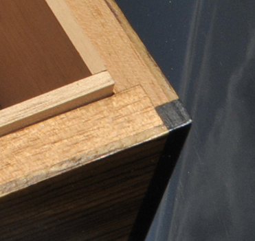
 I agree with the Jon that it doesn't much matter the order of assembly here. For what it's worth, I didn't find it that difficult to line up the edges and ends. Perhaps because I chose to taper the planks aft of amidships, therefore requiring very little tweaking with a sanding stick to fit. On the veneer front, I'll suggest again that, if you have access to a band saw with a good resaw blade, you can easily make your own veneer. In the past, I've made my own as thin as two mil, but could have gone thinner. For the purpose I put it to, I thought I'd rather have a bit more material available to sand at the finishing phase of that project. These photos are of an older version of the humidor, which I gave away as a gift, where I probably went 2 mil plus. In the more recent version, which I made for myself to use as photo boxes, I measured the thickness of the zebrawood veneer. It's 1.5 mil. Ironically(?) I forgot to photograph the photo boxes..
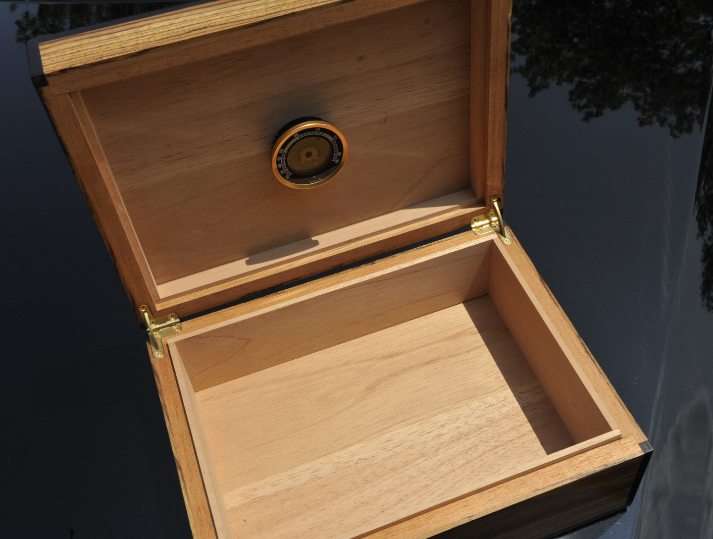
- 233 replies
-
- 2
-

-

-
- Model Shipways
- constitution
- (and 5 more)
-
with the passage of time, even you won't notice (or remember). one of the few blessings of aging.. 😁
-
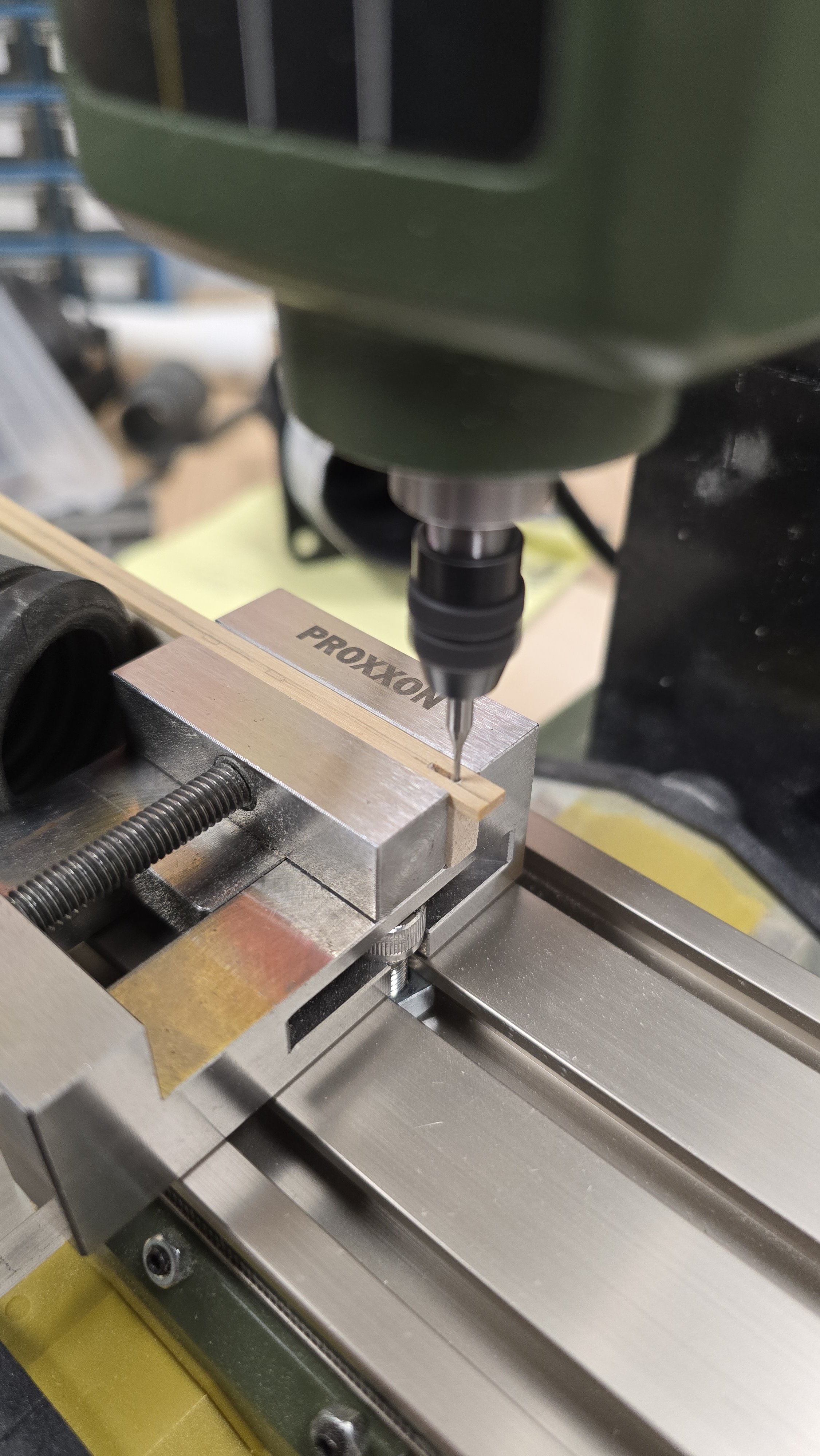
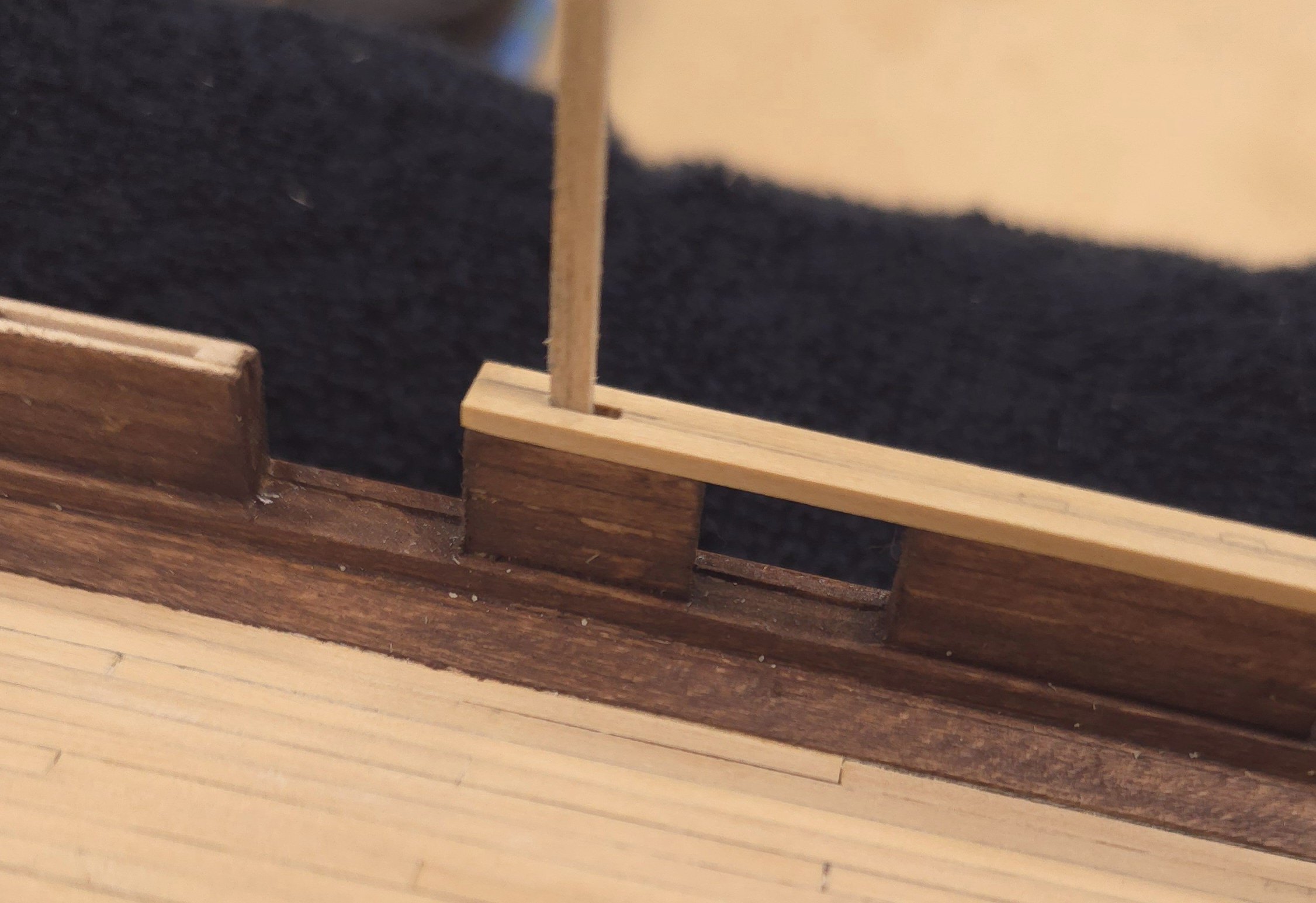
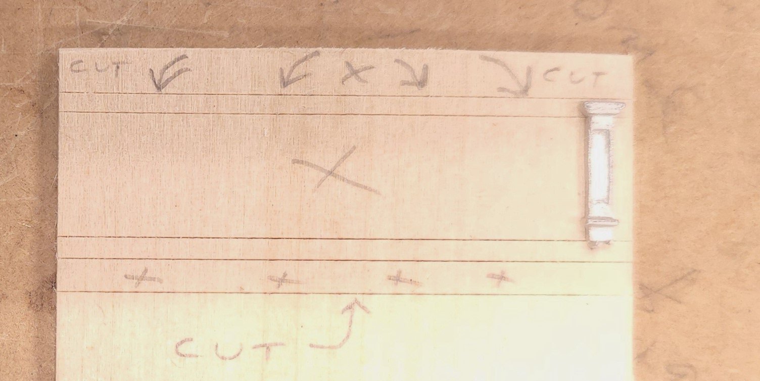
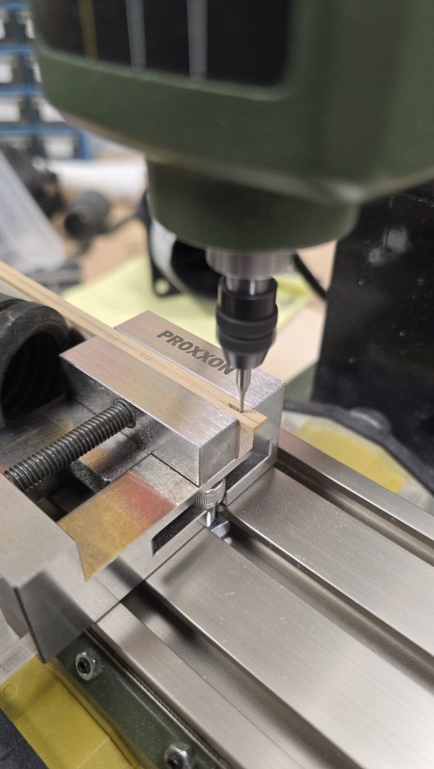
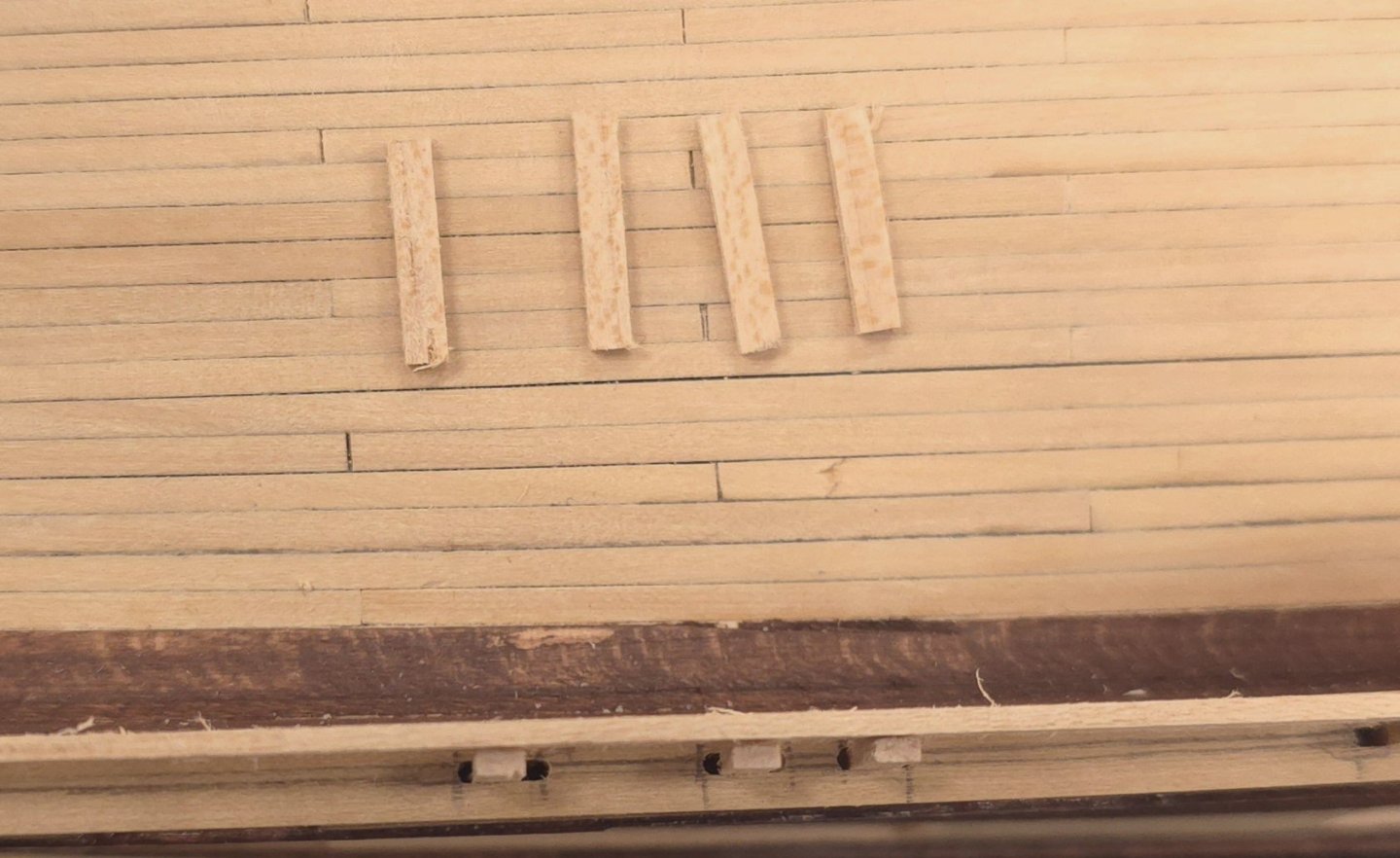
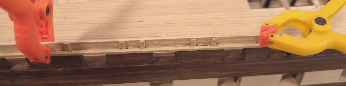
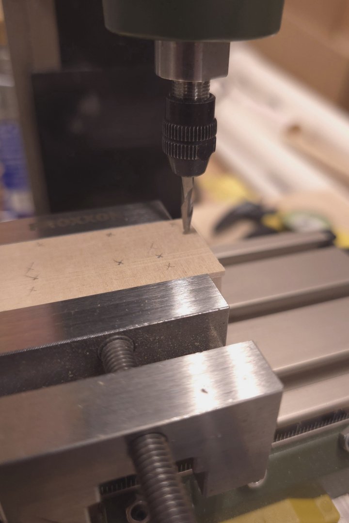
The gunport lid hinges are temporarily on hold. So I'm moving on to the main rail. I haven't yet started the forward portion with the big curve, because my stock isn't as thin as mustafa's. I may have to do some milling before I can do the laminating. However, I have made use of my milling machine. Turns out that one of the cutters is pretty much the same diameter as the thickness of the pins that hold the rail to the top of the bulwarks. No need to buy toothpicks her Bob Hunt's practicum. I used the same material for the pins that I will be using for the planks that go up above the main rail. Nothing is glued in yet. I just had a thought. Perhaps I'll make those pins stand just a bit proud of being flush to the bulwark planks. Then I will mill a shallow groove down the center of the bottom of the topgallant rail, which should make centering that a piece of cake.


-
USS Constitution by mtbediz - 1:76
Der Alte Rentner replied to mtbediz's topic in - Build logs for subjects built 1751 - 1800
How opportune! I'm working on the rails myself, only I'm trying to make them out of boxwood, which does not bend well or easily along the wide side. I've already broken several small lengths in the process. I'm going to switch immediately to your laminate method. This is my lucky day. Thank you Mustafa. -
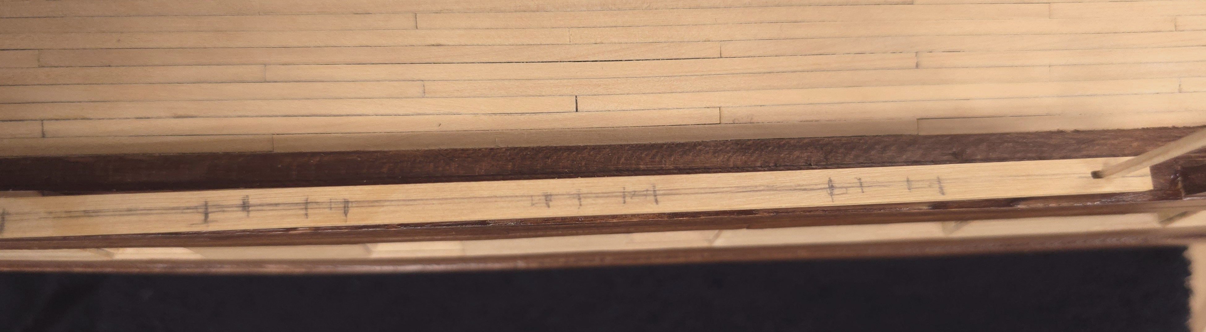
I'm working from the Hunt practicum. The deck forward of the center hatch is made up of parallel decking, but in Chapter 4, on page 63, Hunt begins the discussion of planking the stern half of the deck with, "You’ve probably already noticed that the aft end of the ship is narrower than amidships." Then follows that up with "That means we are going to have to start tapering our planks". That's when I checked the plans, and, sure enough, the planks are indeed tapered aft of amidships. I don't have them in front of me at the moment, so I can't confirm whether they are also tapered to forward, but since I was following the practicum, at this point in the build, I didn't think about it until I read the above. I did in fact do the tapering aft. Here's the link to my build log at around that stage of the planking: (click on the light blue rectangle immediately below. Navigate to the beginning of page 10 of my build if the link takes you to page 1 instead) If you scroll back a bit from there, you can see how I went about accomplishing the tapering of those deck planks using a thickness drum sander. Before I committed to the tapering, I checked at least a half dozen other builds of notable builders here. Only about half of those did the tapering, so you are in good company. (again, scroll back a little further to see my research on that topic).
-
That is an excellent question. My thought is that it might be very difficult to shave a precise 1.5mm off of the bulkheads. There will be more "fairing" after your first planking. So, some of the material you wish to pare will come off at that time. I can't think of any real downside to having a smidge more material on the planking, as long as you allow for this in the rabbets. I would leave the bulkheads as they are. You're moving along at a pretty nice clip. Congrats.
- 233 replies
-
- 1
-
-
- Model Shipways
- constitution
- (and 5 more)
-
I will add my voice to the chorus. Can't wait to see you get started. Happy Thanksgiving to one and all..
-
Because my family in Florida is perusing these pages today, I'm adding the most recent photo. Happy Thanksgiving to the snowbirds.
-
USS Constitution by mtbediz - 1:76
Der Alte Rentner replied to mtbediz's topic in - Build logs for subjects built 1751 - 1800
Drat, Looking at your photo (below), I noticed that I missed a few details on mine. If I can find them again, I have some more work to do before installing them. Of course, If I can't find them, I'll have a model to draw inspiration from. Nice work, as usual, sir.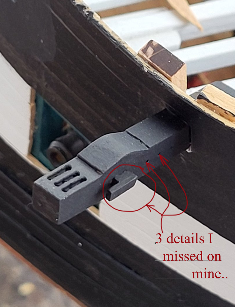
-
Tried that. I just don't have the dexterity to hold tweezers in one hand and another tool in the other to push the part into position. Perhaps the problem with the ones I'm working on now is that I have those pillars already glued to the transom. There's very little space to maneuver between these and where the hinges belong. For the transom, given how thin these hinges are, I think my best would be to cut hinge shaped slots into masking tape and use the tape as stencils to paint on the hinges. Plan B would be to omit them altogether. I will try gluing a hinge on the as yet un-affixed lids for the gun deck. ..after the holidays. Thanks for the suggestion
-
Your plan to paint and add the waterways later is solid. I noticed you're not tapering your deck planks. That should make that job a lot easier. Looks great.
-
I just had an amazingly disappointing session at the shipyard. I spent the solid hour trying to get a single hinge on one of the stern gunport lids. Nothing I have tried works. The hinge sticks to the tweezers or my fingers or falls to the floor. It just can't Wrangle it into position where it needs to be. Does anyone have any tips on how best to put these hinges on the gunport lids? I'm thinking about just painting them on now.
-
USS Constitution by mtbediz - 1:76
Der Alte Rentner replied to mtbediz's topic in - Build logs for subjects built 1751 - 1800
Hasn't Mustafa's ship already sailed on that Jon? Happy Thanksgiving at your sister's either way! -
USS Constitution by mtbediz - 1:76
Der Alte Rentner replied to mtbediz's topic in - Build logs for subjects built 1751 - 1800
Having read Gregg's comment on my build log, and then seeing that you're just making the catheads, I'm asking myself: Self, where did you put the catheads you made oh so many months ago? As always, it's a pleasure watching the master at his craft. -
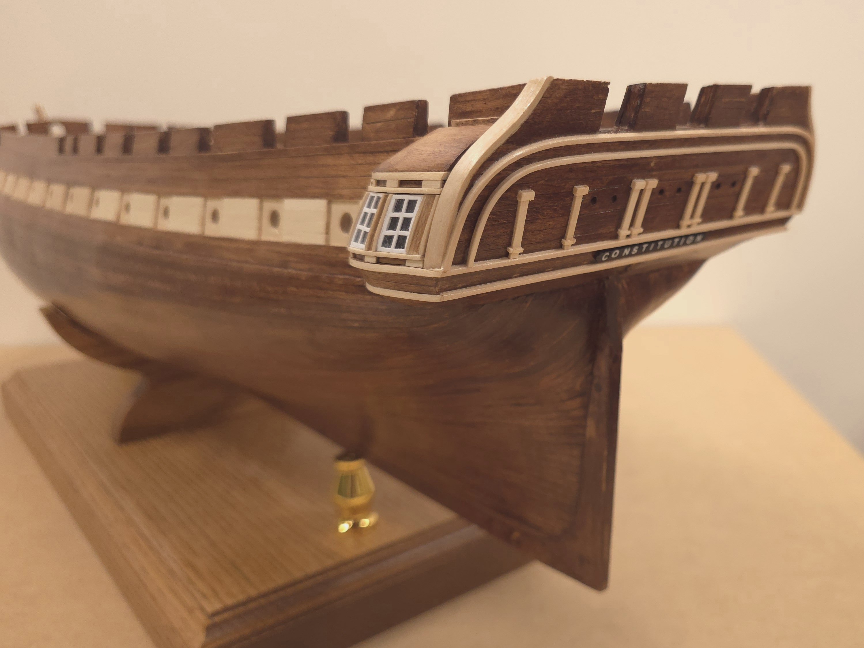
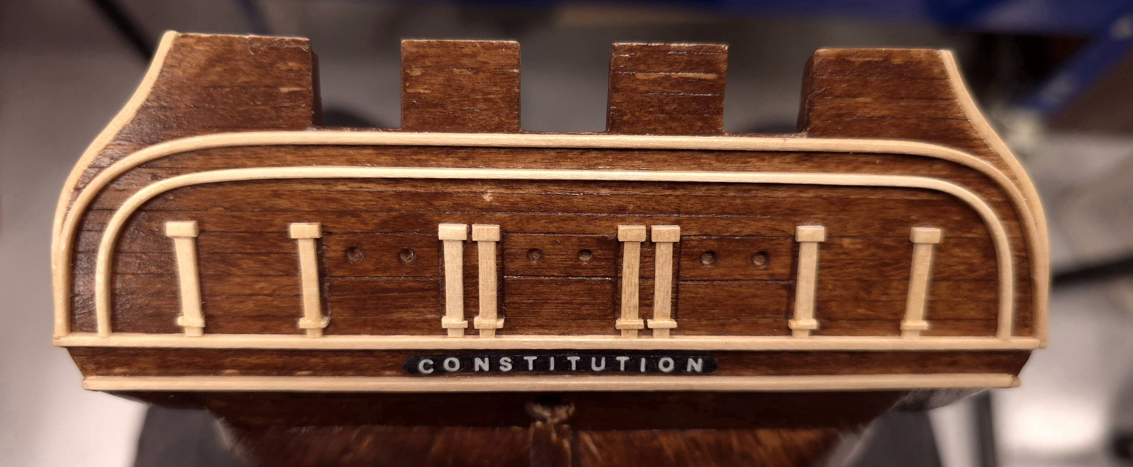
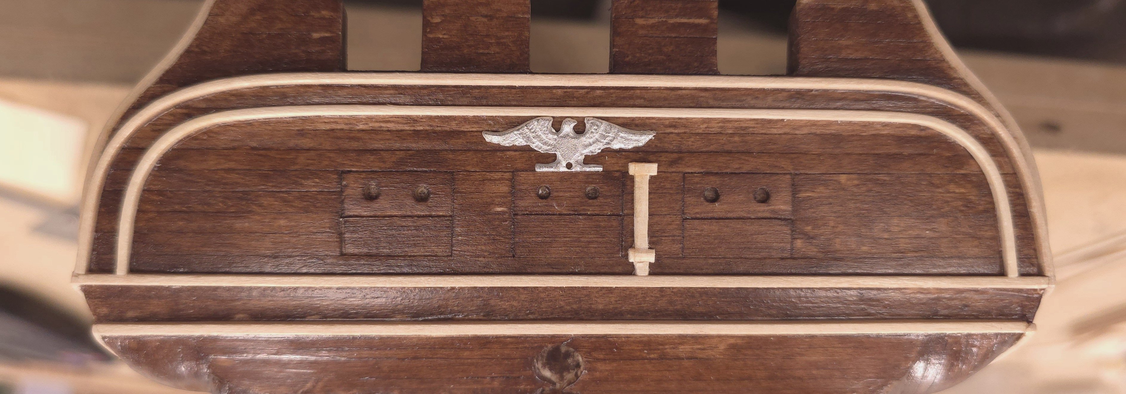
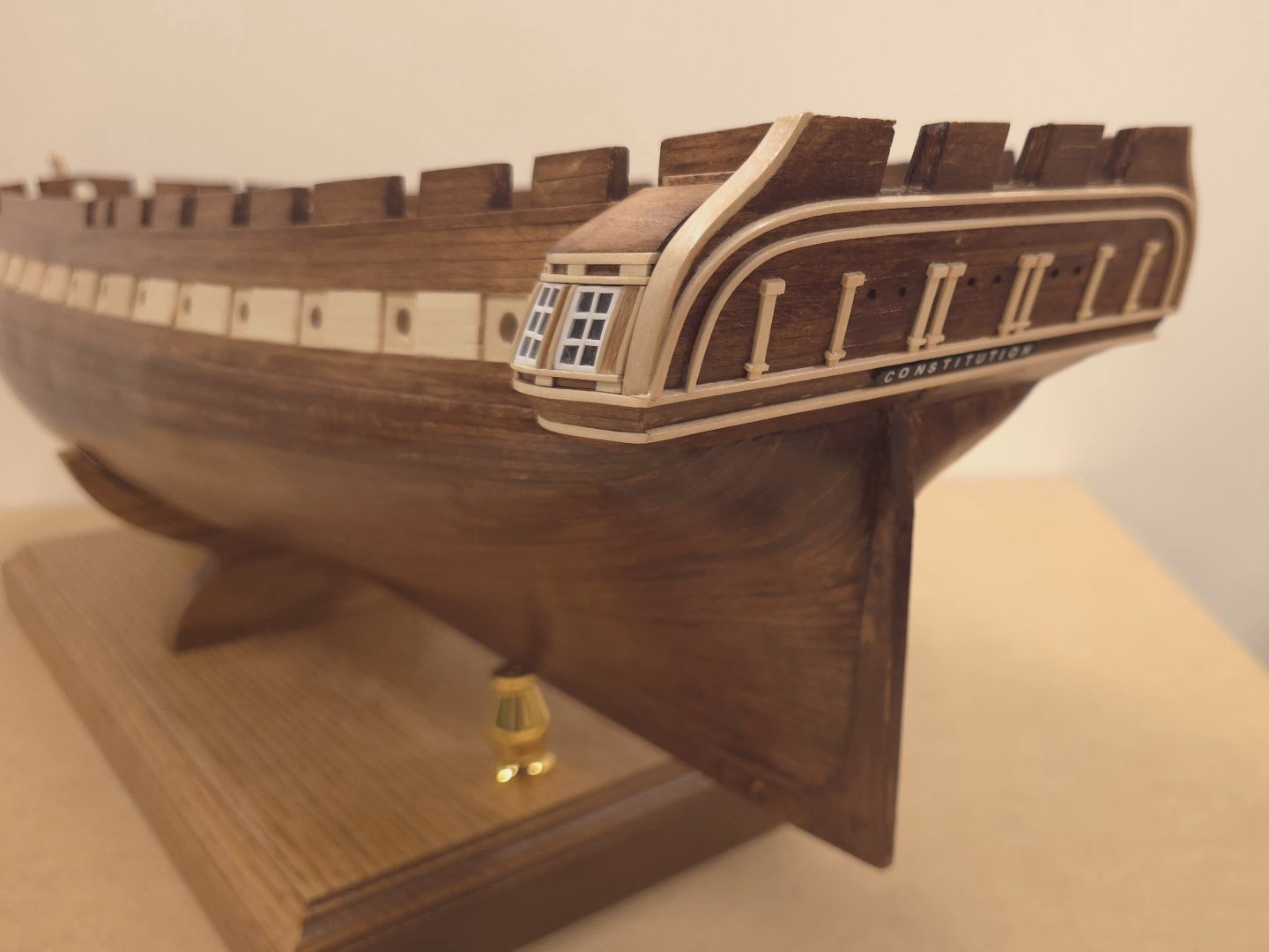
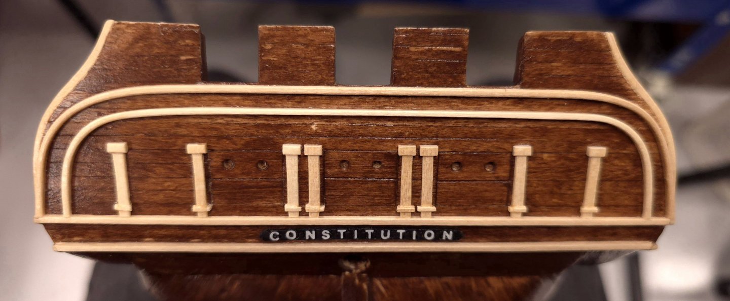
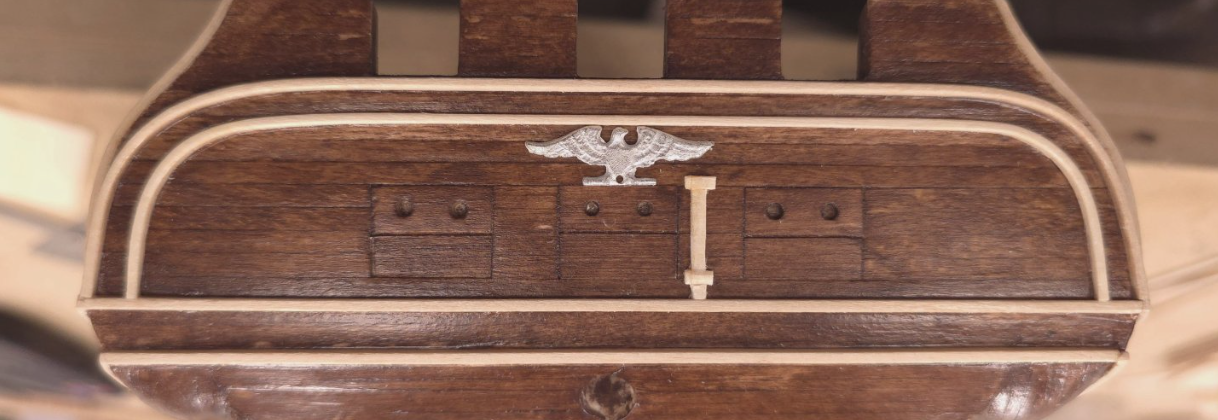
Having been sidetracked with matters mechanical in my Shipyard, I haven't gotten much done in the last few days. Today at least I managed to deal with the Constitution name plate. I took a tip from the Bob Hunt method and obtained the dry transfer decals he suggested using. I didn't see the need to make a separate name plate out of styrene. Instead I just sanded the top of the laser cut piece that came with the kit, painted it, and positioned the dry transfer decals over the outlines of the letters spelling Constitution. Since I already have the black/white contrast on the gallery windows, I thought I'd repeat that theme here, as opposed to staining the name plate. It's a good thing that the dry transfer decals from Woodland Scenics we're still available online.
-
USS Constitution by mtbediz - 1:76
Der Alte Rentner replied to mtbediz's topic in - Build logs for subjects built 1751 - 1800
Good save! -
Whew. I'm glad this is done..
-
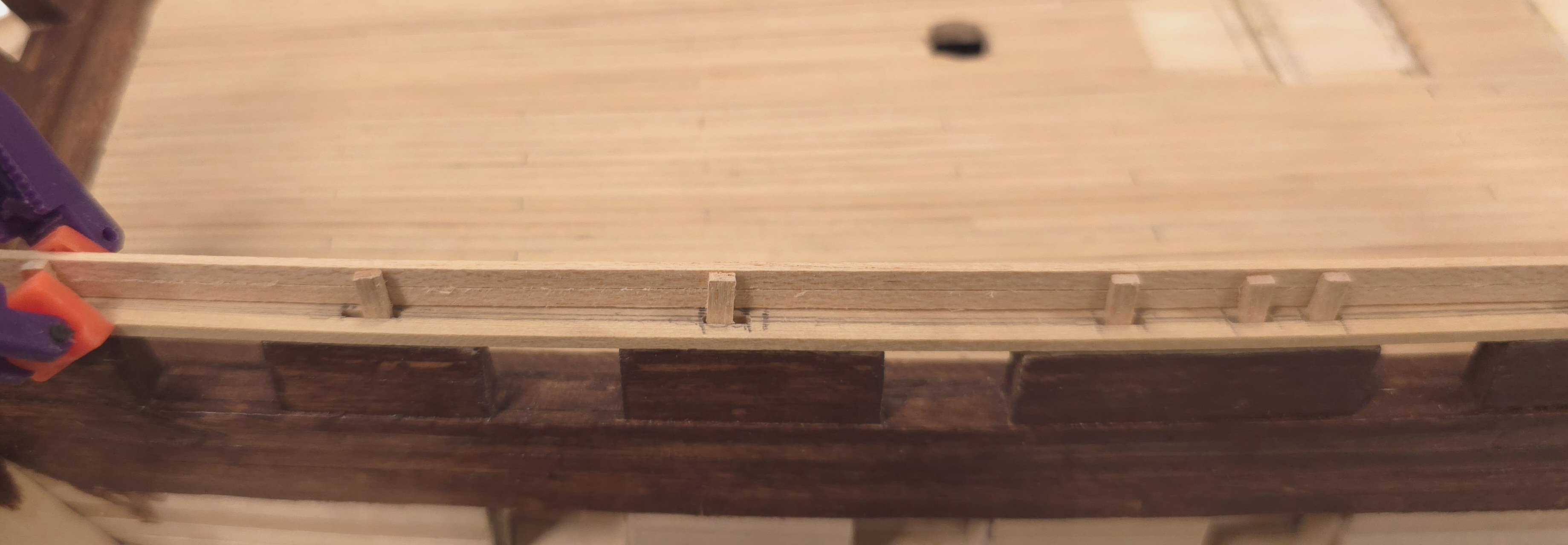
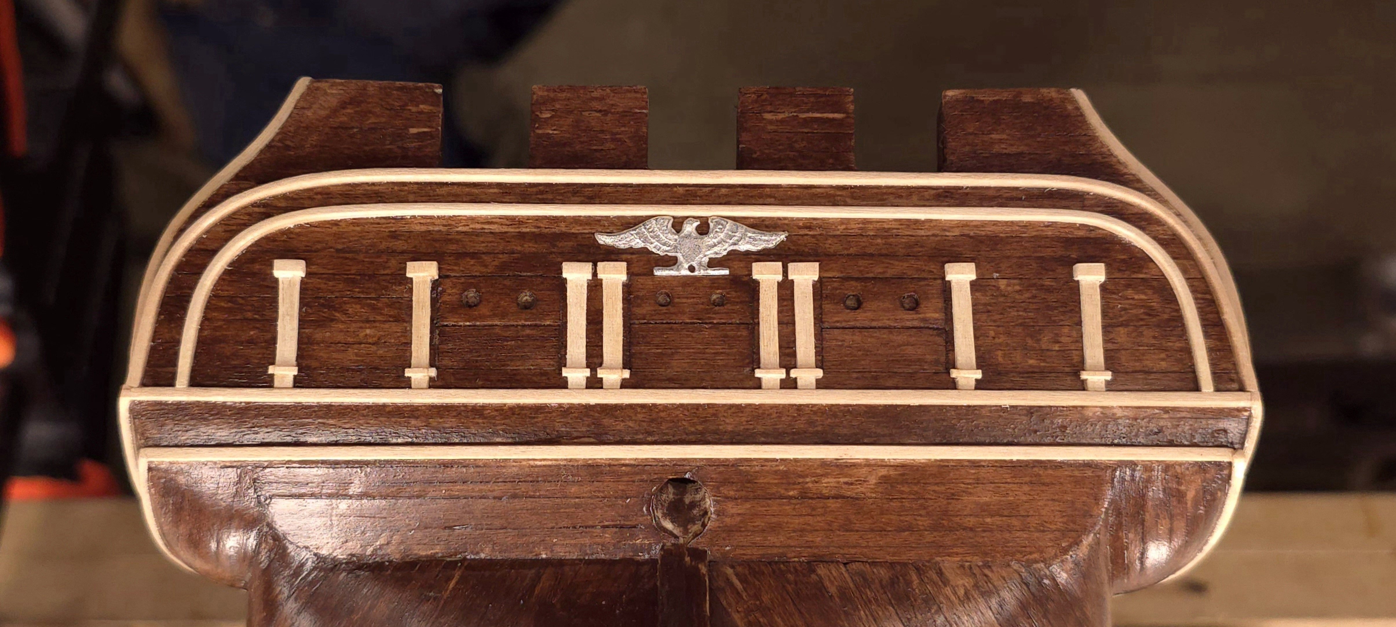
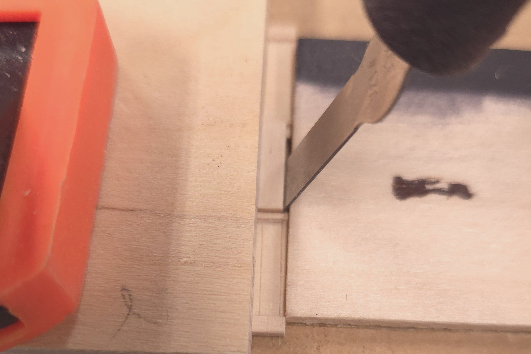
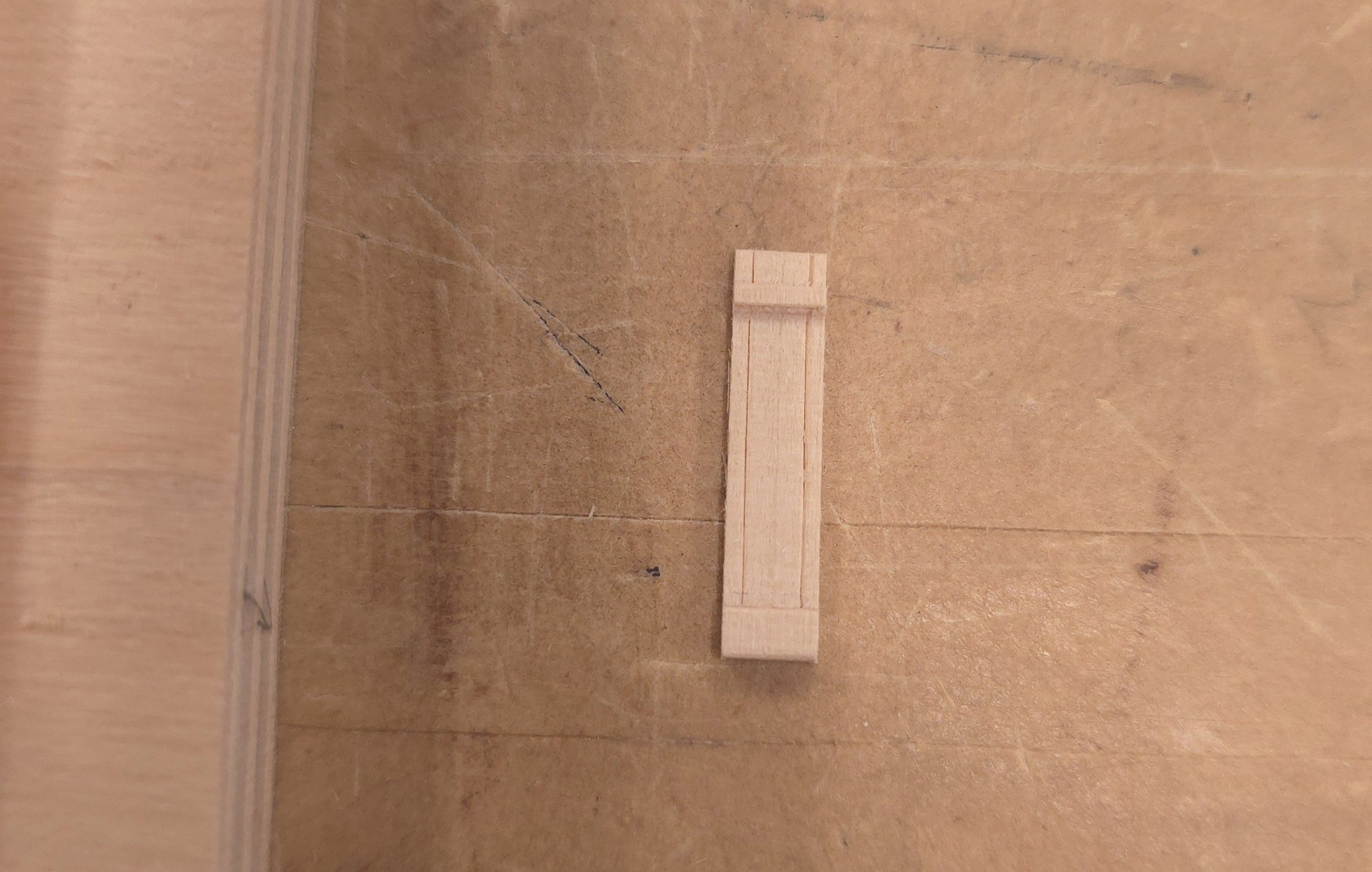
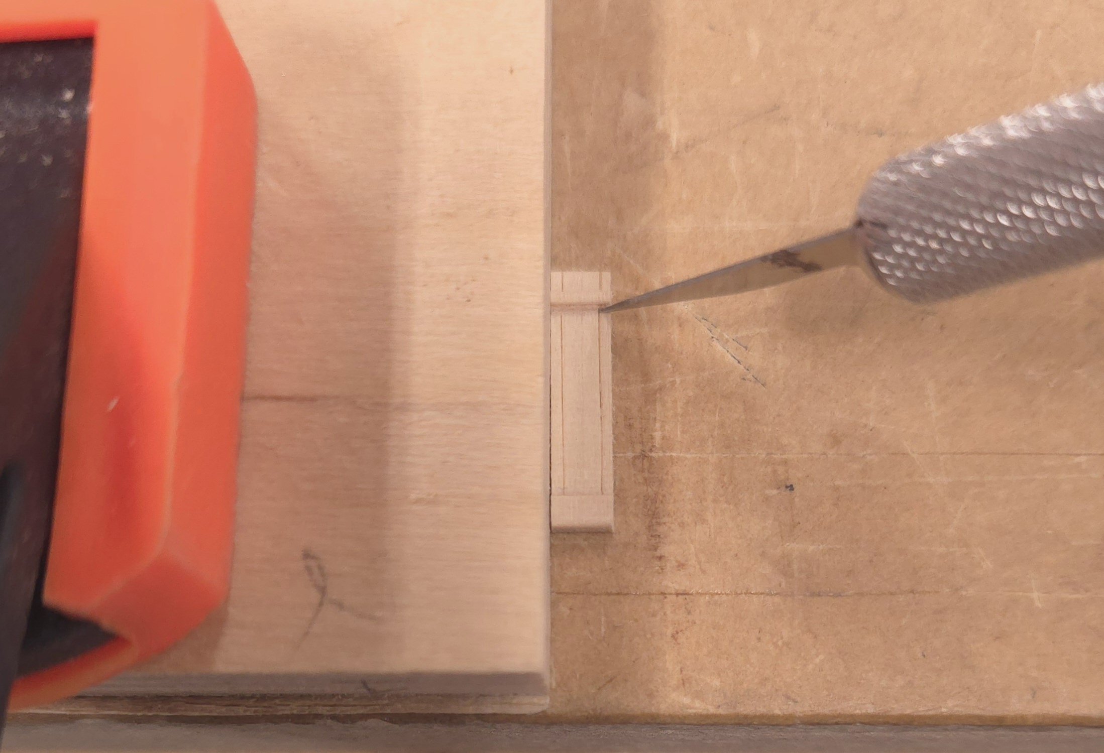
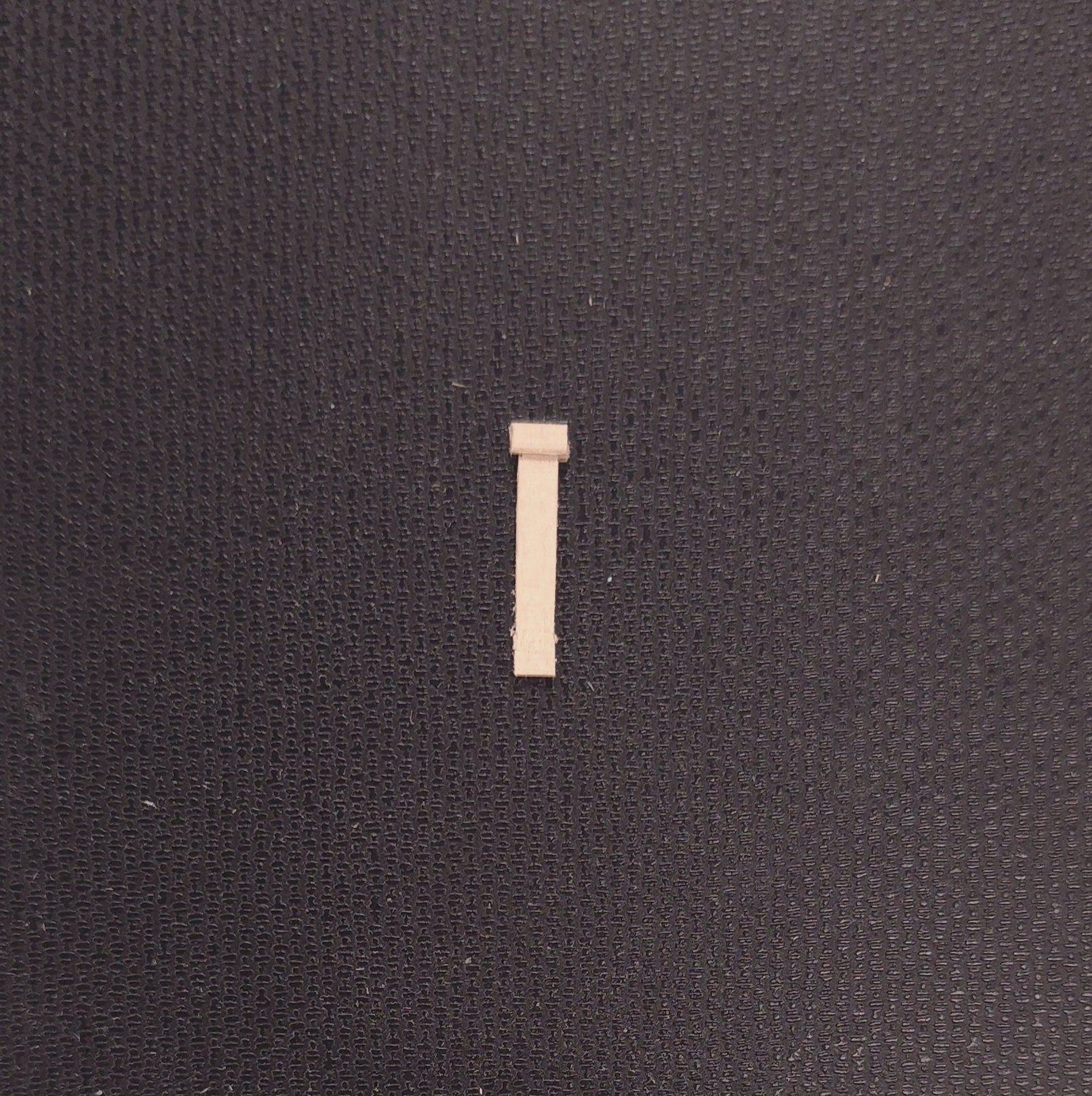
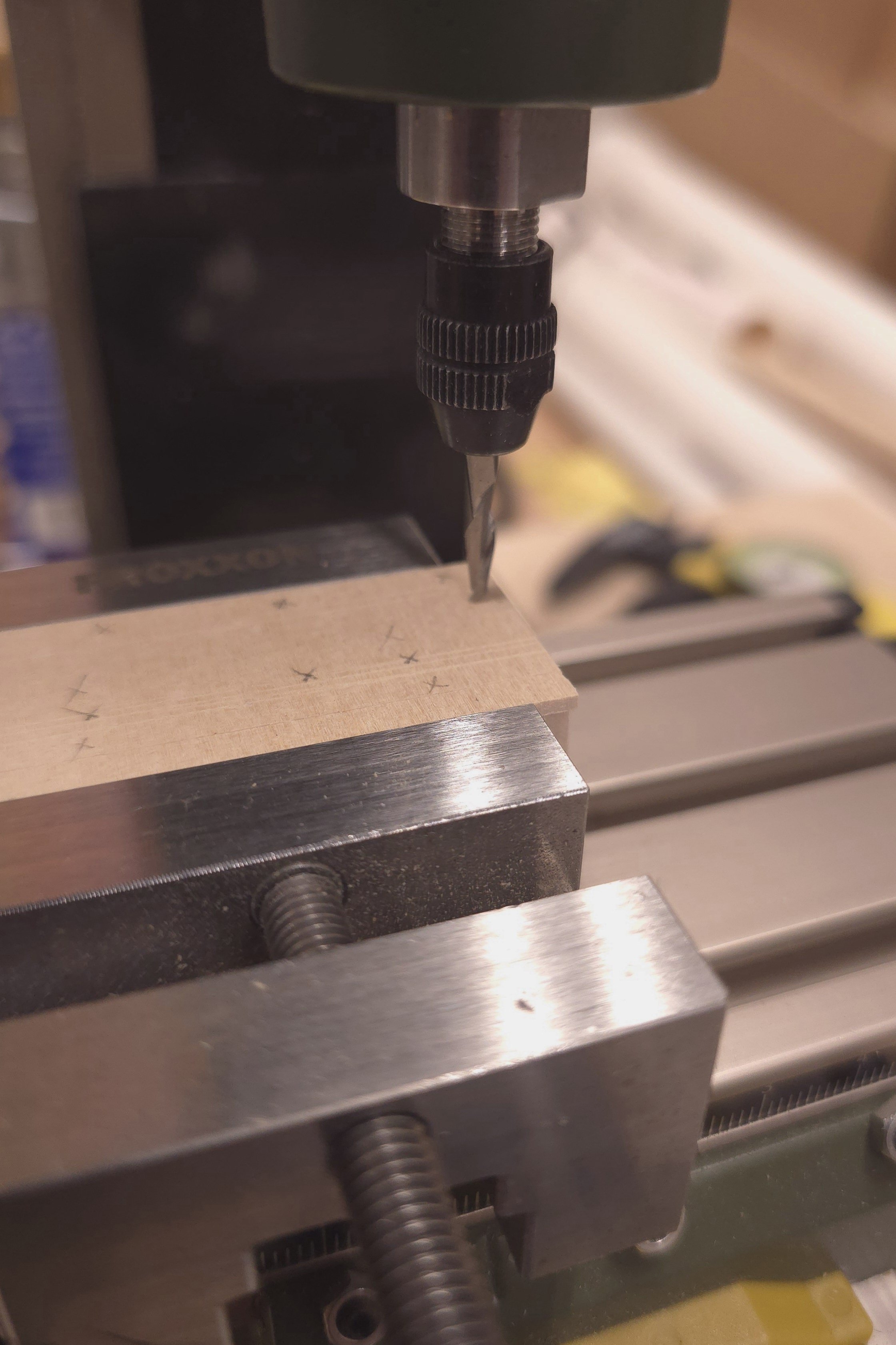
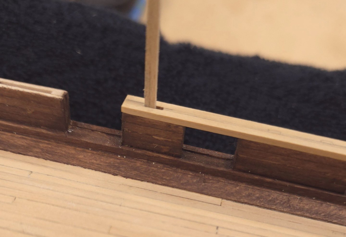
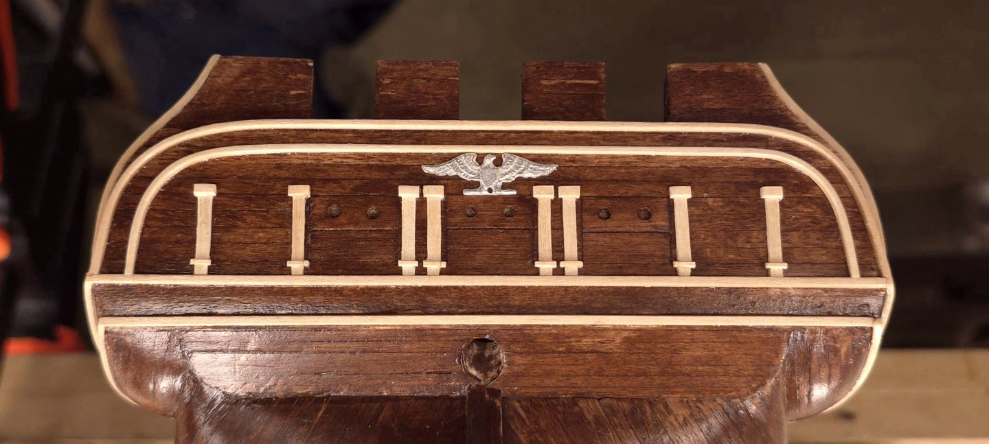
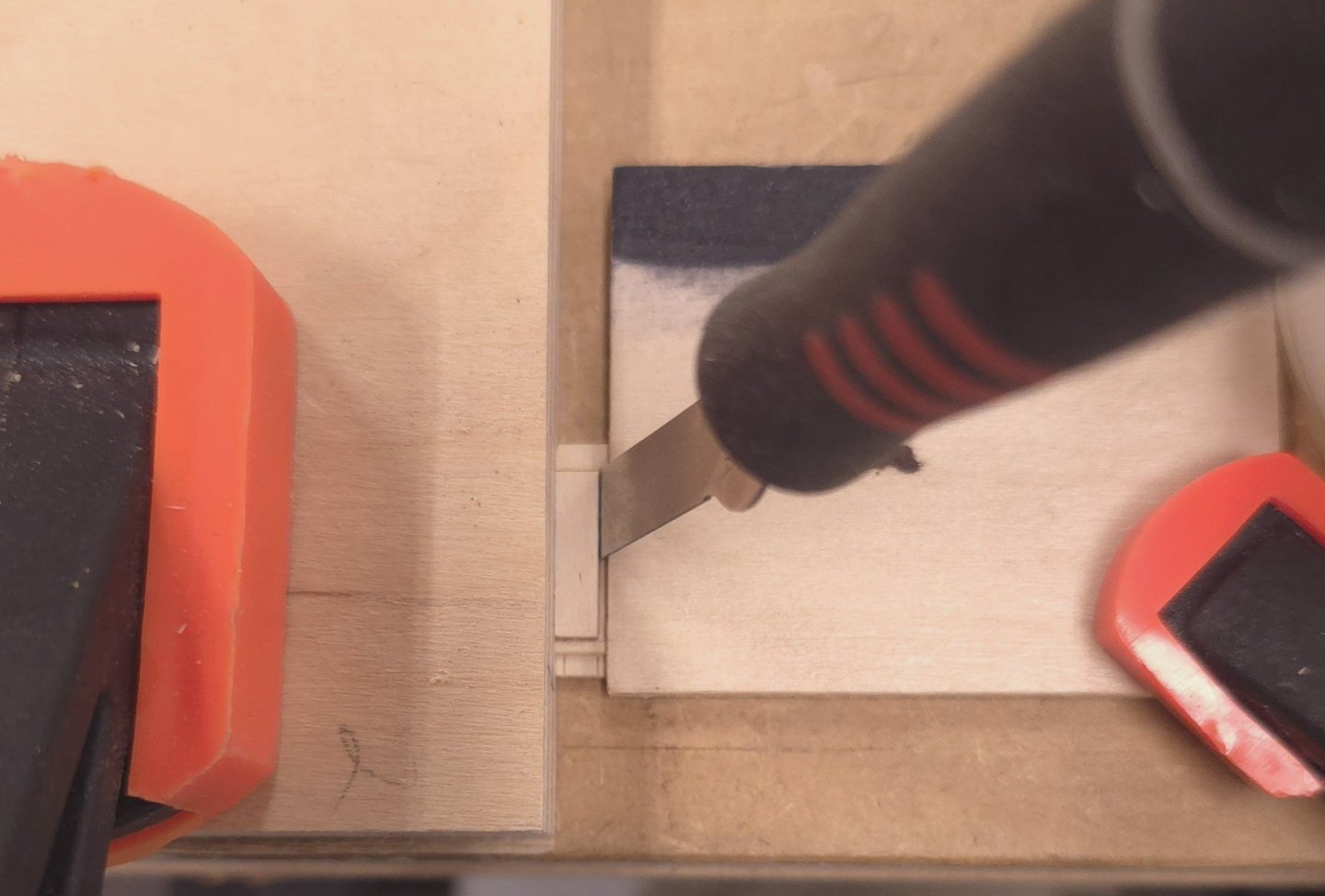
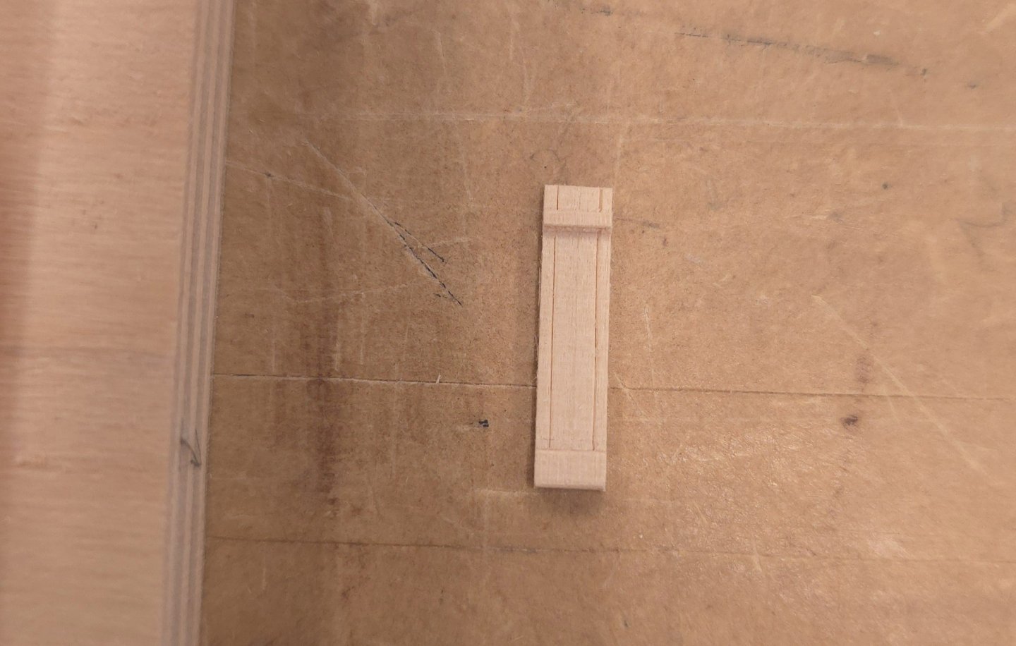
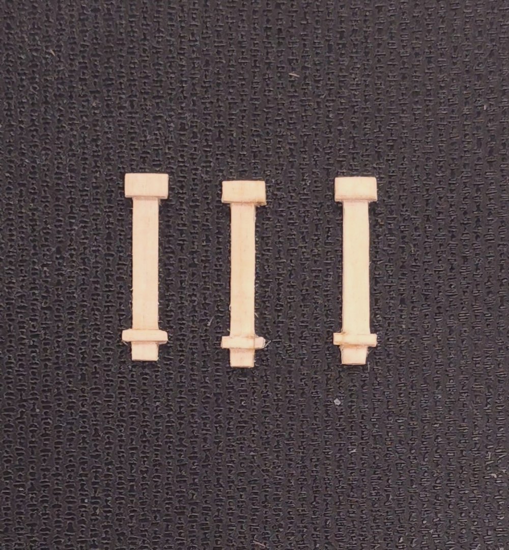
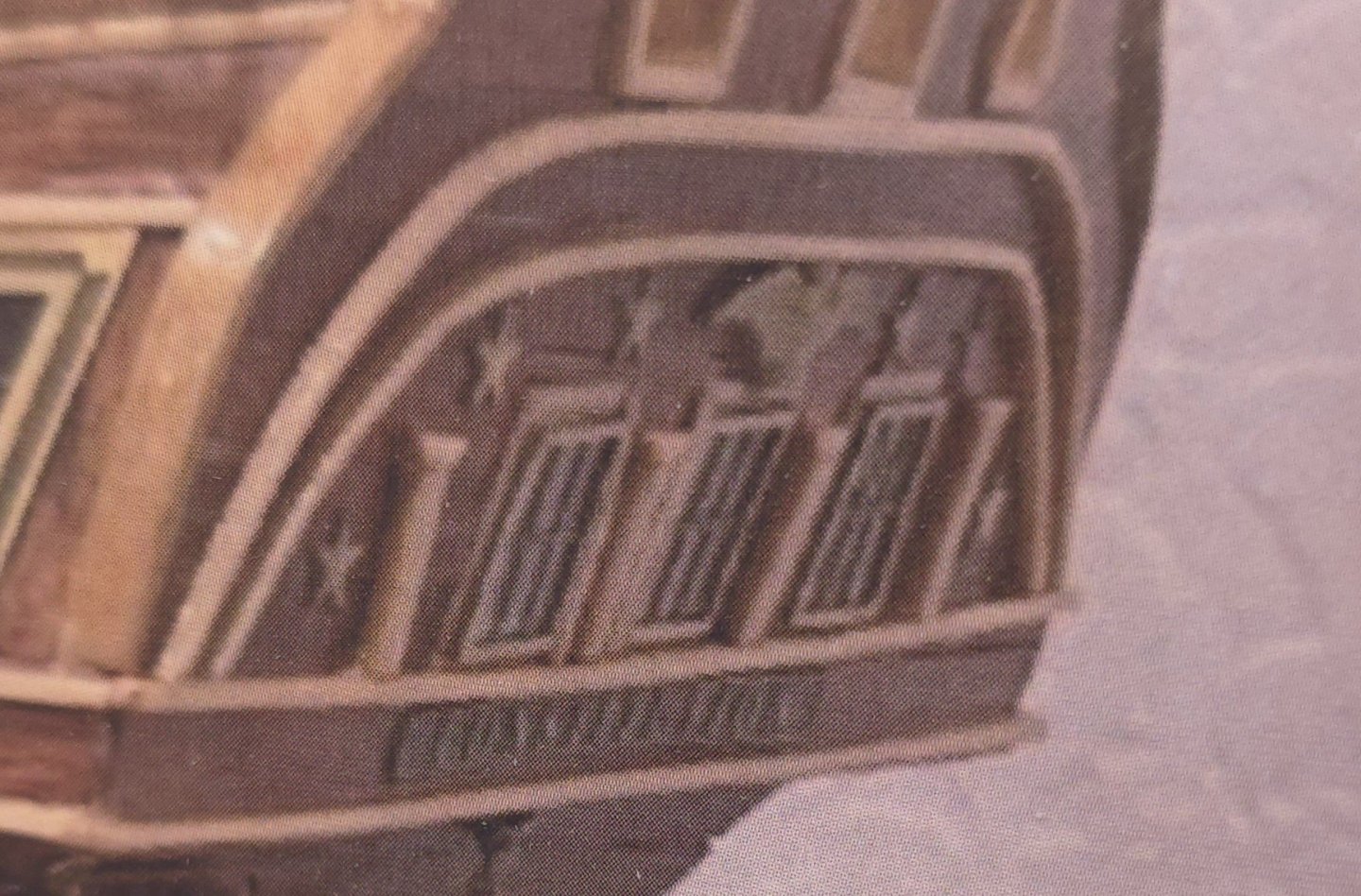
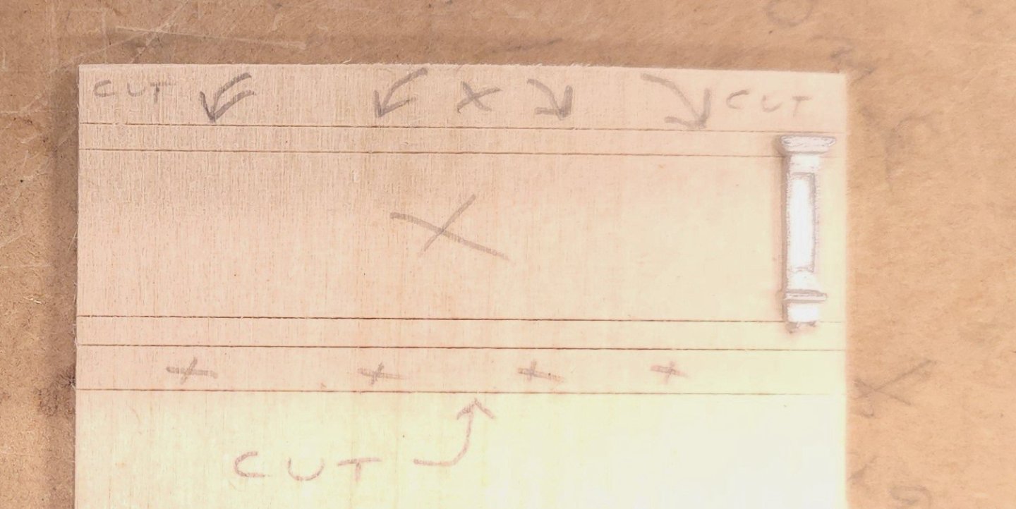
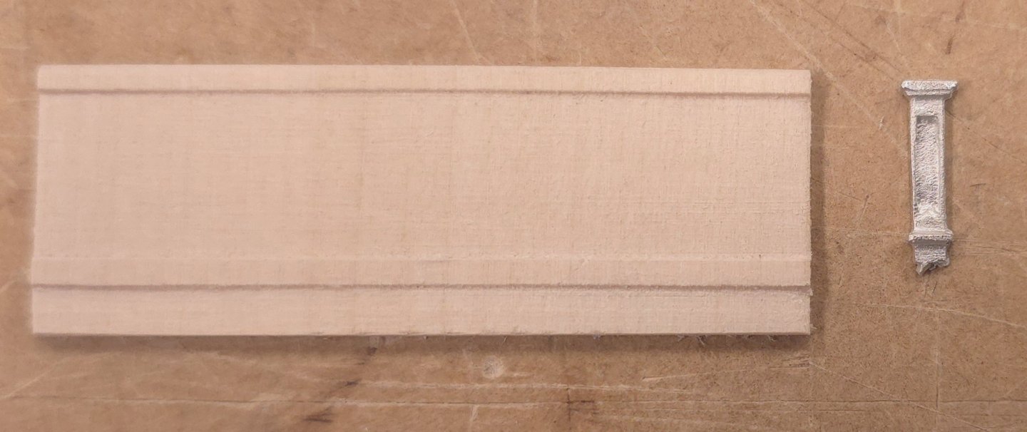
Trying to construct these pillars from the boxwood left over from planking the deck was problematic. And with the boxwood this close to the curved Basswood molding, the difference in materials was notable. Therefore I used the same material - basswood, and procedure to start making more pillars but with a narrower bottom cross piece. Time consuming work to be sure.. I use the same milling method I used yesterday, but narrowed the strip for the lower cross pieces. Using a spacer, I made marks where I needed to remove material. Then, ever so carefully, I pared away the material for the indentations. Despite supremely careful handling of very sharp tools, breakage occurred on every piece, requiring repairs. If this continues to plague me for the remaining five pieces, I will just get rid of the lower crosses all together, and go with the solution exhibited in the Constructo kit.


-
Jon, You may have noticed that I'm not exactly following the plan. Given the screwup with the lower molding, for example, I'm forced to make the pillars longer than the plan. And since I already used basswood for the round molding on the transom, I think I may be stuck using the same for the pilasters, to keep the color there consistent. However, since I'm less than satisfied with the first one I made, I'm pretty sure I'll be revisiting the process, and may yet try boxwood, as I have some left over from the deck planking. I'll see how I feel when I return to the shipyard..
-
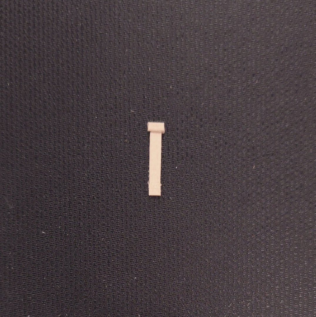
I started working on the pillars for the transom today. Not 100% sure I like the result. I'm going to look at the pictures for day and decide if I'm going to take a different approach. Here is one of those cases where styrene would have been a fabulous material to work with. Not so much basswood.. I'm thinking that the bottom cross member should be narrower, perhaps half as wide..

-
There you go, Haiko, you now have the attention of one of the most knowledgeable contributors on the subject of the USS/Frigate Constitution at this site. You'll not want for plans or pictures going forward. 😄
- 233 replies
-
- 1
-
-
- Model Shipways
- constitution
- (and 5 more)
-
Doh! Of course, that makes absolutely perfect sense. I can't believe I didn't remember that. Go for it! By the way, if it hasn't already come up, you'll also need to make planking for the spar deck.
-
You've nailed it on the head! That's all these kits are. If I hadn't found this website and the Bob Hunt practicum, I would be completely lost.
- 233 replies
-
- 2
-
-
- Model Shipways
- constitution
- (and 5 more)
-
In my humble opinion, if you have the kit, use the stem that came with it. I don't see an appreciable difference between the drawing you showed and the part in the box.