HOLIDAY DONATION DRIVE - SUPPORT MSW - DO YOUR PART TO KEEP THIS GREAT FORUM GOING! (Only 36 donations so far out of 49,000 members - C'mon guys!)
×


Bluto 1790
-
Posts
324 -
Joined
-
Last visited
Content Type
Profiles
Forums
Gallery
Events
Everything posted by Bluto 1790
-
 Tom, That's some great progress there with these deck beams going in. Your build is coming on apace and it's spurring me on with mine! (Not that anyone would notice due to the absence of any recent reports!)
 -
Pandora by marsalv - FINISHED - 1:52
Bluto 1790 replied to marsalv's topic in - Build logs for subjects built 1751 - 1800
Hey Marsalv, I'm wondering if you intend to charter your ship for sailing holidays/courses when it is complete? We know you're trying to kid us that you're building a model ~~ but we're on to you . . . we KNOW your ship is a full-size replica of the Pandora!!! -
Hi Tom, That progress of your looks great! I very well know what you mean when you say "With this being my first scratch build I can really see how important it is to think several steps ahead." DON'T ASK ME HOW I KNOW ! For the first 3 years or so of my build I had virtually no contact with this encyclopaedia of model ship building (M.S.W. forum) and pretty much blundered on in my own ideas of how things should be done. Of course you'll have guessed that many "procedures" were performed in the most unconventional ways! When I made my first gun carriage I found that with its gun mounted it was going to be a very tight fit in the port, so I had to make the carriages all a little lower in order that the barrels would come properly out thru the ports. If I had positioned the upper and lower gun deck planking about 2mm lower I wouldn't have had that problem . . . but there was no way that I was going to destroy the ship to get the guns to fit, so I adjusted the carriages instead! It's about 4 weeks since your previous post but it has been more than 6 weeks since my last 'progress' report . . . but I HAVE been beavering away at a few tasks -- and have been "Re-beavering away" at some of the same tasks! (Read "Re-beavering" as 'having to do the same task again . . . and sometimes again!') So, despite my efforts over these weeks I don't have anything to post. I'm just glad that someone's Leopard is going somewhere!
-
HMS Victory by willz
Bluto 1790 replied to willz's topic in - Build logs for subjects built 1751 - 1800
Very clever and effective jig, William! I've made a few jigs, and none of them could be called 'pretty' . . . but they work! -
Looking great, Tom! . . . and I didn't turn my laptop sideways - - - I just tilted my head!
-
ancre La Salamandre by tadheus - 1:24
Bluto 1790 replied to tadheus's topic in - Build logs for subjects built 1751 - 1800
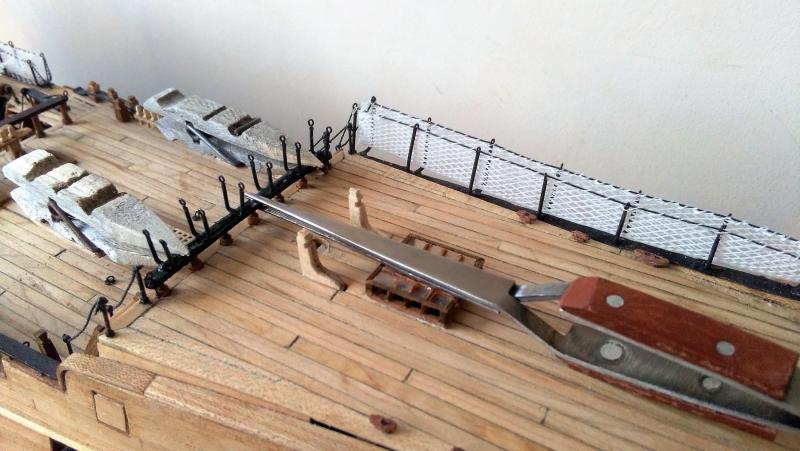
Hello Pawel, Geert just beat me to ask the same question -- your blade looks quite unusual to me . . . it almost looks like some kind of gearwheel instead of a saw blade. By the way -- superb build !!! -
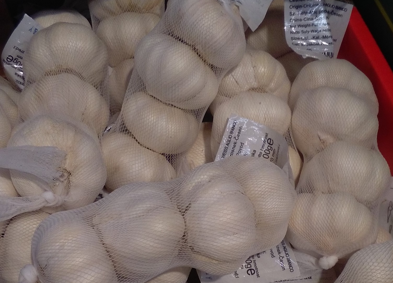
Thanks to Tom, Steven and Alan for the comments and to all the others for the likes. Steven ~ I find that munching on them little garlic cloves keeps the vampires away . . . it also keeps everyone else away! Alan, when I first began this build I had virtually no experience in model building and really only had my own ideas of how I should go about it. Then, as I progressed I eventually found this forum and I've learned a huge amount from the fabulous builds recorded here. When I first started I felt that there would be so many aspects of the build that would be far beyond my level of skill, and while my efforts aren't near the same league of so many builds on here, I've been surprised sometimes that I have been able to do certain tasks that I had earlier believed would have not been possible for me. You mentioned the turning of small diameter spindles, and while I'm now past the point in the build at which I'll need these, I've since seen a couple of builders here who turn spindles inside a partially profiled metal tube in order to support the full length of the spindle as well as creating consistent replicas . . . and when I come to my next build (10 or 15 years from now!) I'll certainly be giving that a try. Now, here's what I think - - - I think you shouldn't be waiting 2 years to start your build . . . I want to see your log on here soon!
-
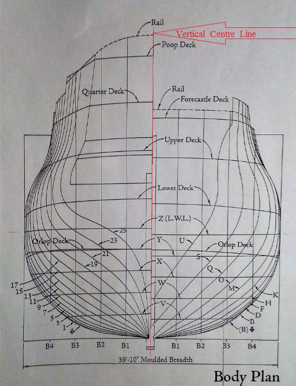
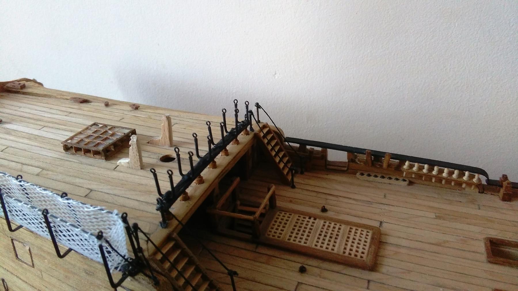
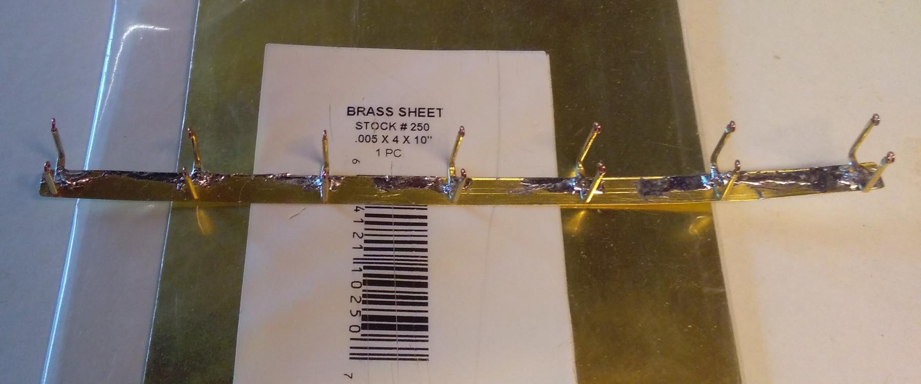
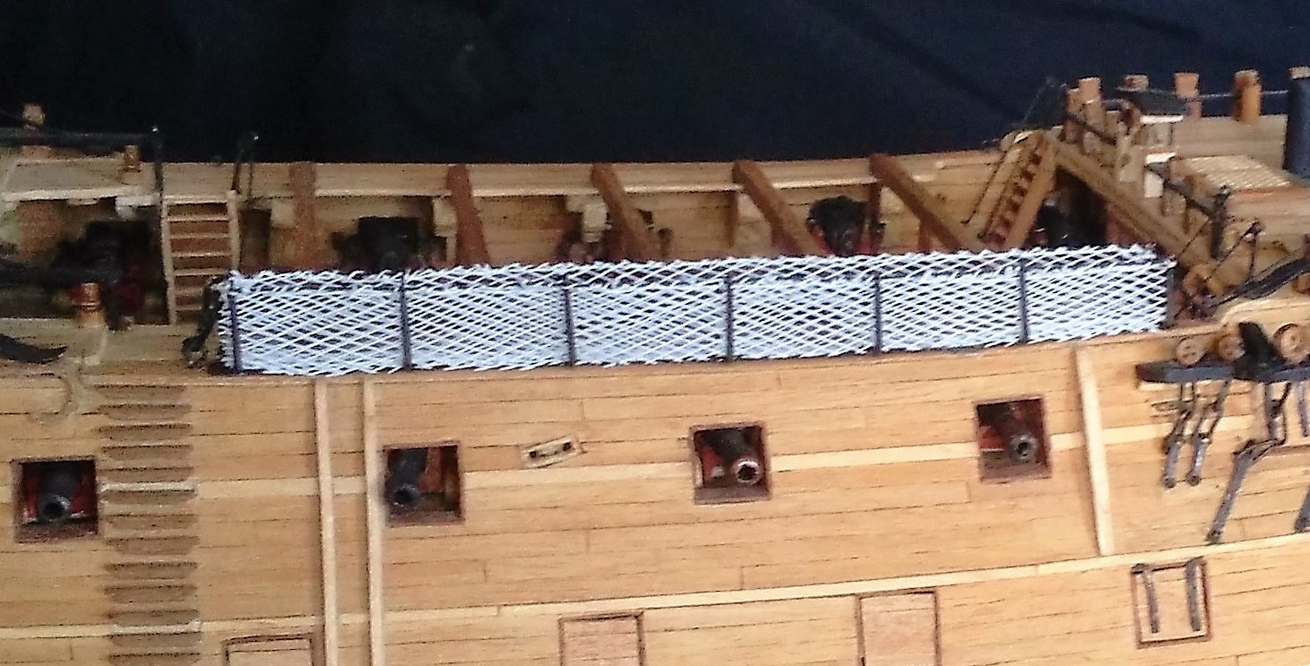
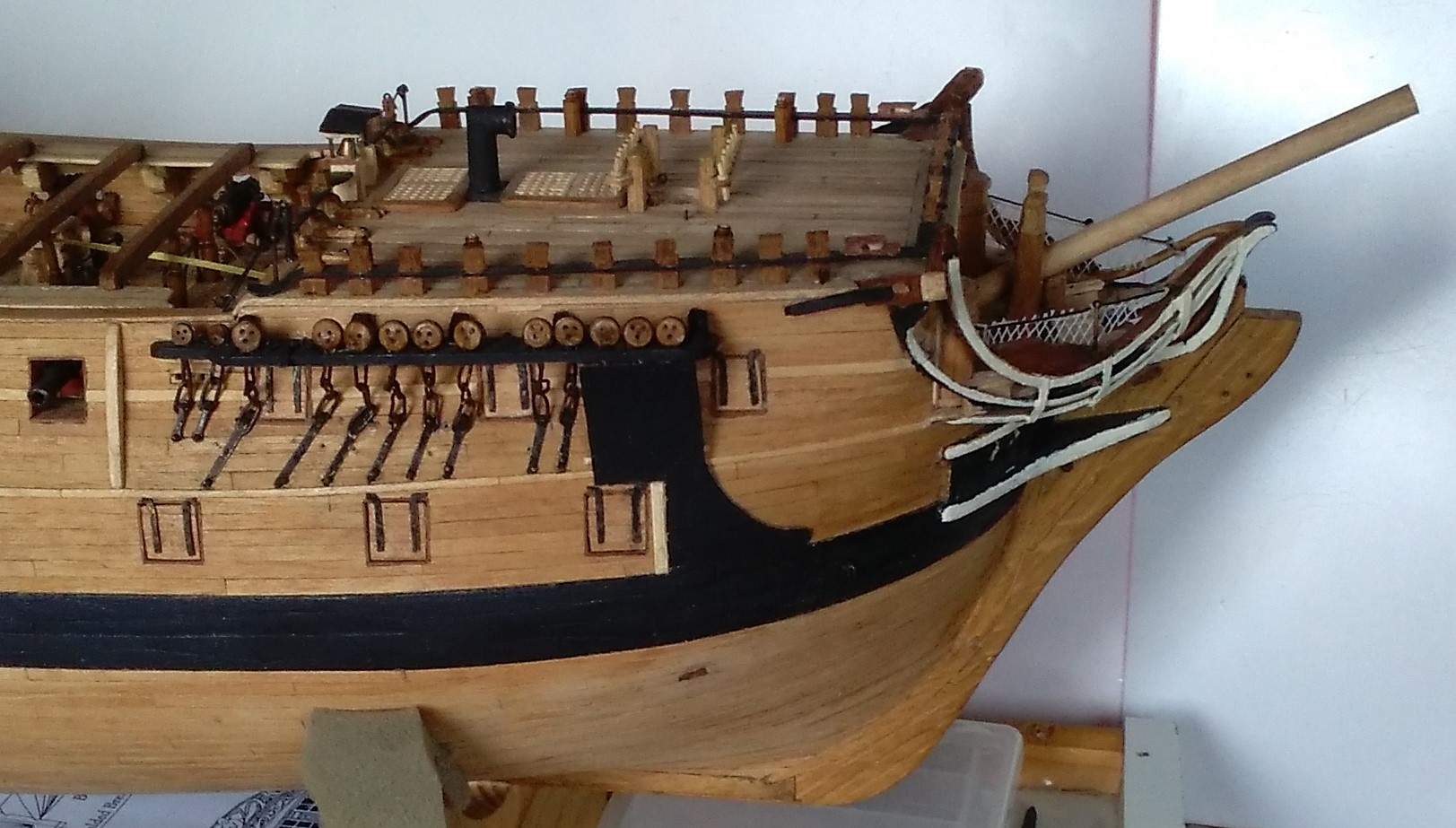
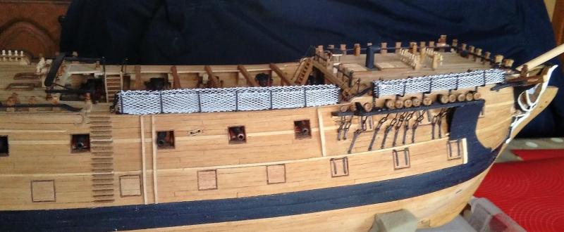
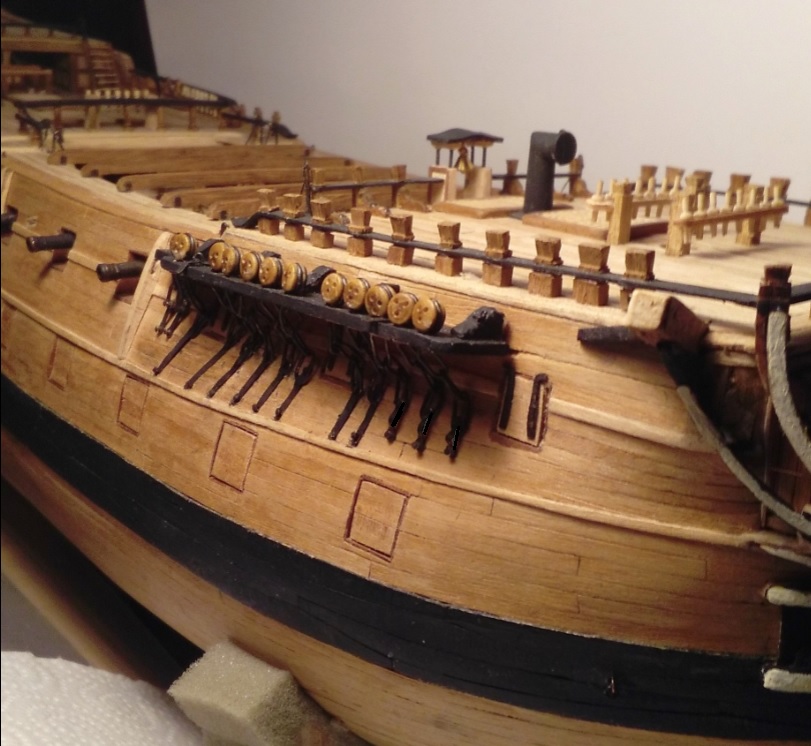
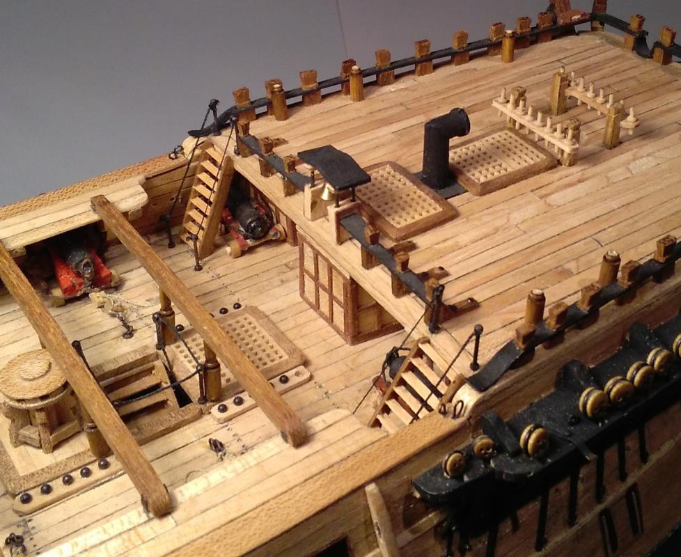
Thanks Steven. Cranes; Phase 4. With the previous cranes I have been able to glue and NAIL them on as there has been relatively substantial structure onto which to to nail them. (Either the hull side for the foredeck cranes, and down onto side rail/bulwarks for the waist and poop cranes.) However, with the athwartship cranes for the poop rail and quarterdeck rail there is virtually nothing to which to nail anything . . . so, it's up to the epoxy resin to hold things together there. As with the two previous sections of hammock cranes, these were soldered onto a brass strip and glued to the rail. Here the brass meets the rail and spends the night in the clamps while the epoxy does its job >>> The epoxy worked! >>> Ropes fitted >>> . . . and with garlic netting >>>


-
Well Tom . . . I think your method is just GRATE! Seriously, that's quite ingenious . . . and time-consuming. The principle is similar to that on my box joint jig where the first cut slots over the guide piece while the second cut is done, and so on. Only difference is my box joints are done on my table saw with an 8 inch dado blade of 5/8 inch width instead of a cut of only 0.040" wide! (My hat's still off!) Jim.
-
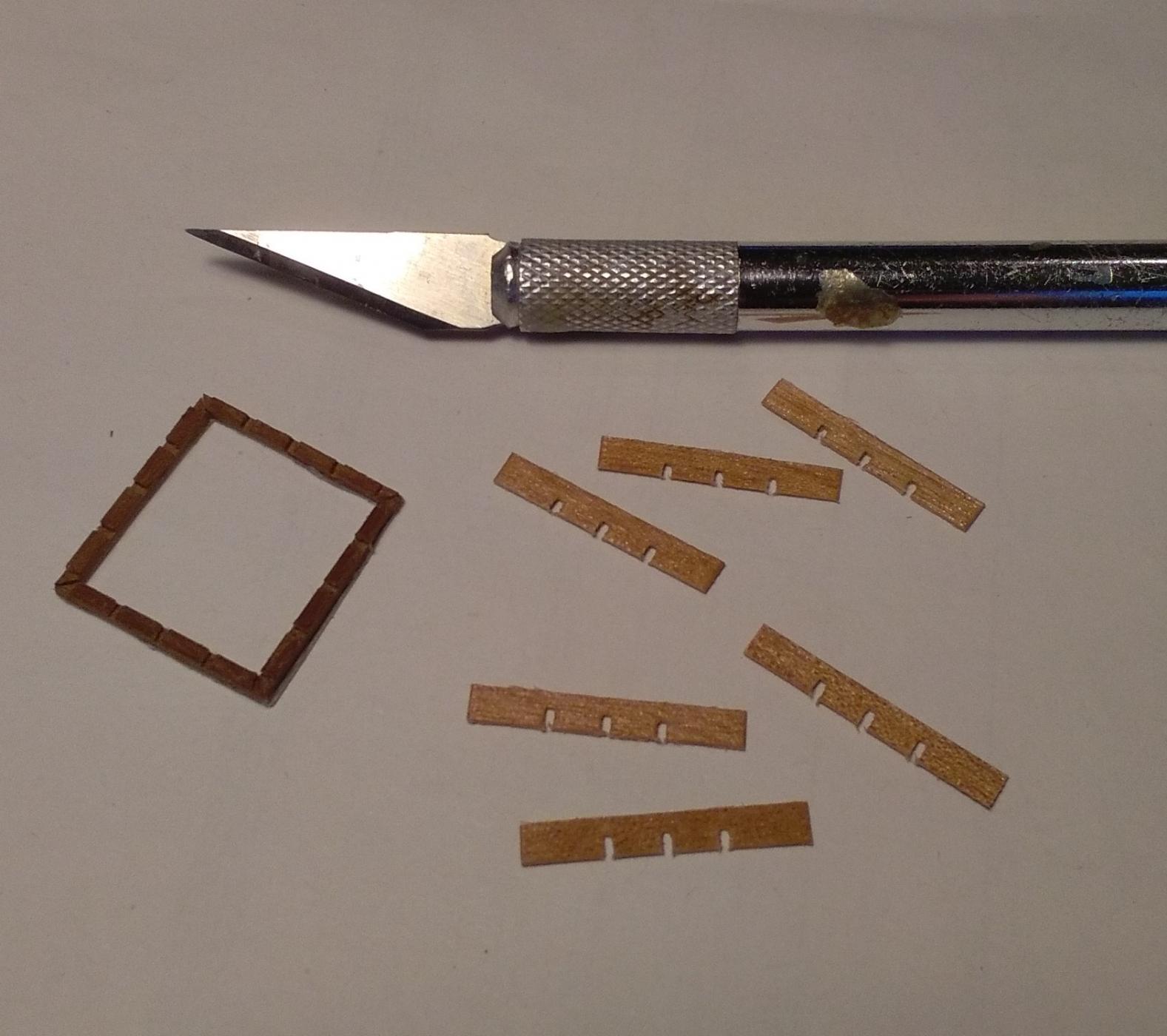
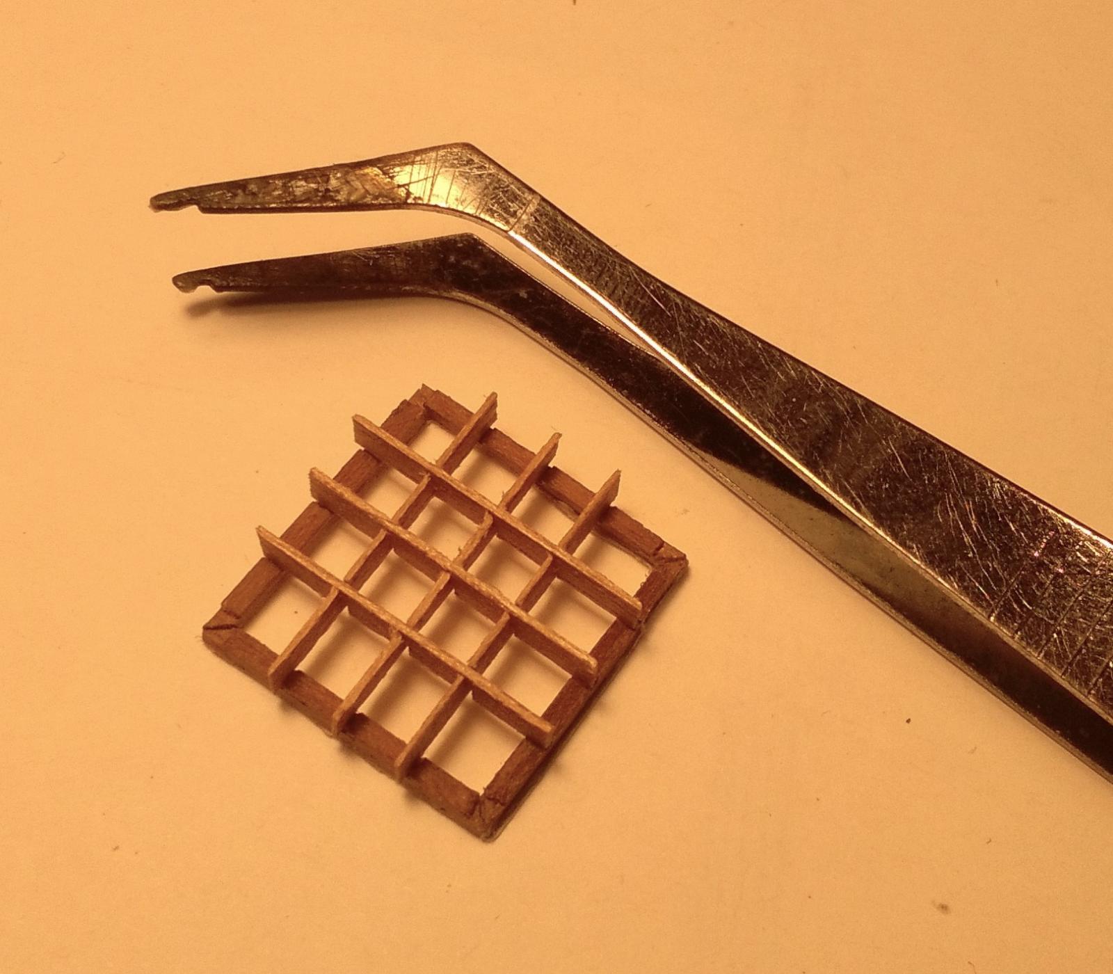
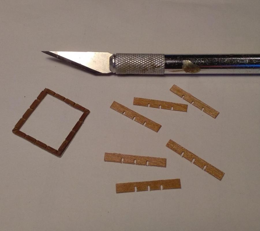
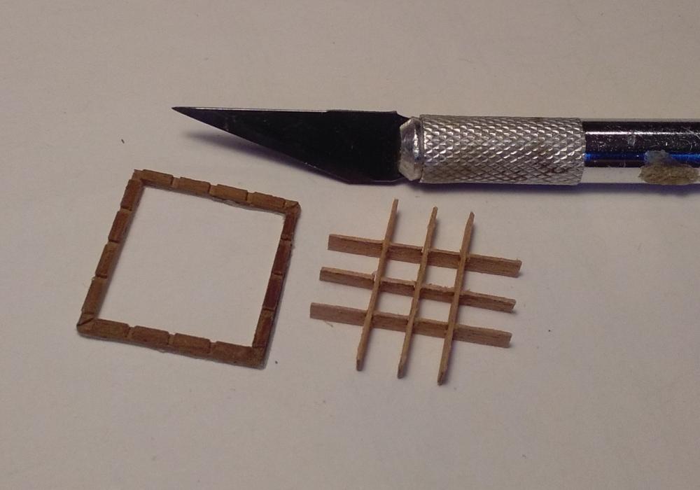
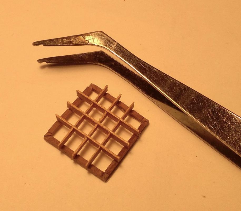
Hi Tom, Some very nice progress there! Congratulations on these gratings. When I was at the gratings stage in my build I attempted to make my own but was having too many failures and in the end I copped out and bought the commercially available ones and assembled these instead. I know how tricky them pesky little things are, as the scale of my build is only just a smidge bigger than yours ~ so I take my hat off to you! Now . . . you need to show us that jig that you used . . . . . I'll be waiting here to see it!
-
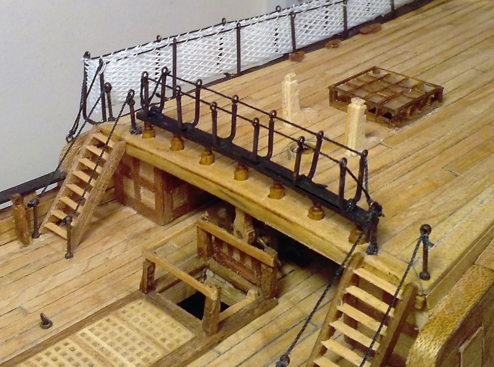
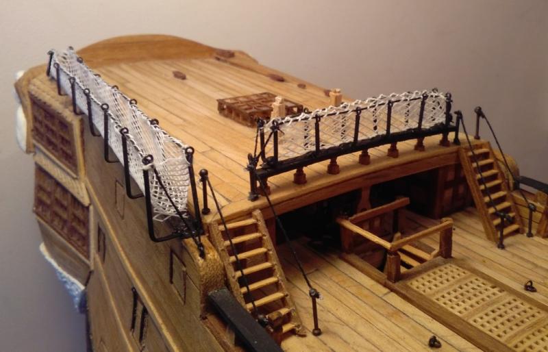
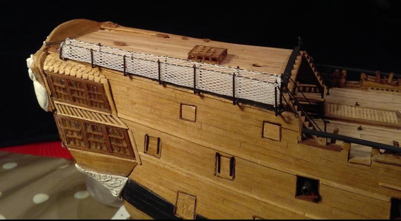
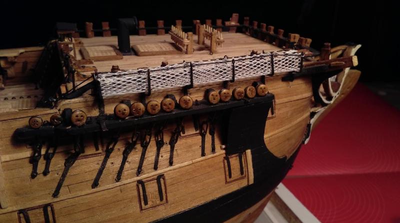
Thanks for the comments, Alan and Steven, and to the others who clicked the 'like' button. (Steven ~ I'm glad your jig works!) Hammock cranes -- Part 3 - - - Poop deck starboard side. Used the same jig as I did for the waist cranes but just had to fit another fence with a slot angled at around 87 degrees instead of the vertical slot. (Of course, just for added fun, none of the cranes here are the same dimensions as any of the others.) >>> . . . with ropes fitted >>> I made these cranes to the dimensions shown in the drawings and fitted them in the positions also shown in the drawings, but when I saw them on the ship I began to worry that the netting would interfere with the mizzen mast shrouds/lanyards. So I mocked-up a dummy mizzen mast, channel and shrouds to test if there would be any clearance between lanyards and hammock netting. It looks like there should be about 1mm to 2mm space so hopefully no fouling between these items. In the hope that there WILL be clearance later, I went ahead and fitted the netting >>> Starboard side nettings all in place >>> . . . hammock cranes/netting - - - just parts 4, 5, 6, 7 & 8 to go . . . . .


- 257 replies
-
- 13
-

-
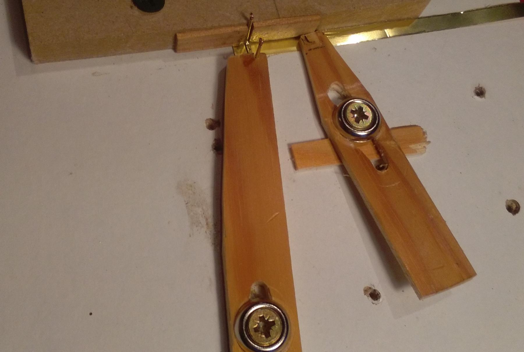
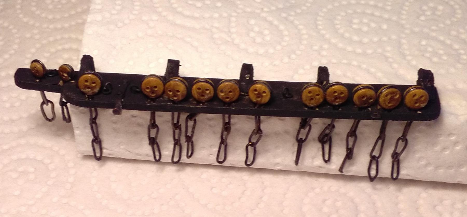
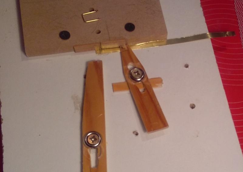
Hammock cranes: Phase 2. While I'm deciding whether to fit the port side fore channel before or after the foredeck hammock cranes, I made a start on the starboard waist cranes. While I had to fit the foredeck cranes individually, I was worried that I wouldn't make a very good job of fitting the others while trying to keep them all vertically parallel to each other as well as being equally spaced . . . so I decided I would try to fit the 7 waist cranes as a single unit by soldering them onto a base plate which could then be taken to the ship and fitted as one unit. I cut a 5mm wide strip off a sheet of 0.005 inch (0.125mm) brass shim and soldered the cranes on to that >>> In that photo above, the soldering looks much worse than in reality. In any case, when blackened, the soldering is almost invisible and it will be completely hidden once the netting is fitted. >>> When I was soldering the 'legs' on to the foredeck cranes I found it very tricky trying to get these tiny parts stuck together (and not burn my fingers at the same time) so I made up a very simple clamping device. Getting these 7 cranes soldered vertically on to the base plate for the waist was also going to need some sort of jig. . . and that's what I came up with --- "some sort of a jig". From some scrap material, I concocted what must be the most crude jig ever seen by mankind! . . . but it worked perfectly. Have a look . . . (please try not to laugh.) >>> In the photo above, the brass base strip is held securely against the fence, and down on to the melamine base by the sliding 'clamp' on the right. In the next picture the crane is held vertically in the slot that is part of the fence, and is being held securely by the sliding wooden 'clamp' on the left. This 'clamp' has a 1mm notch cut into the end that makes contact with the crane in order to prevent the crane from moving to the left or right. Once clamped like this I have 2 free hands with which to concentrate on soldering . . . as well as not burning my fingers! >>> This 'jig' (is it OK to call this thing a 'jig'?) will work for the other waist cranes as well as the cranes for the poop & Q/deck rails, but as the cranes aren't at 90 degrees to the poop side rails I'll have to adjust the vertical slot in the fence to being slightly off vertical . . . and I'll have to do that twice as each side is a mirror image of the other, so what works for starboard won't work for port.


- 257 replies
-
- 14
-
-
Thanks Steven, John and Tom for the comments, and to the others for the likes. John -- 'Imperfections' - there are plenty on this model, but I'm not going to list them for fear that even more people will spot them! Tom -- funny you should mention the garlic Vs vampire thing --- since I"ve been doing these nettings there has been a noticeable reduction in the number of vampire sightings around here!
-
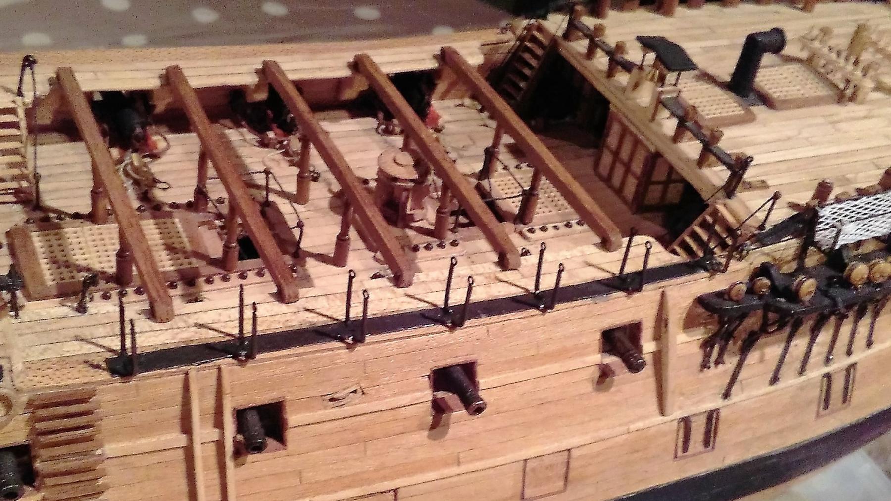
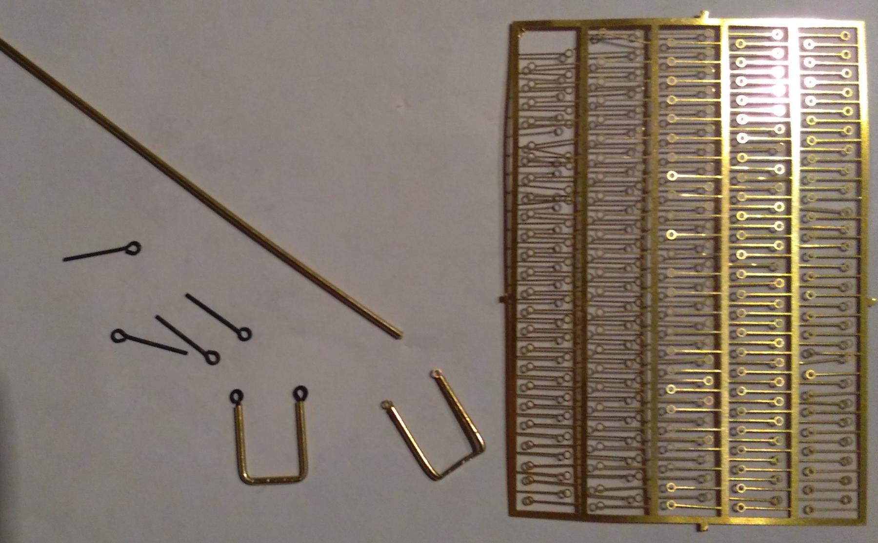
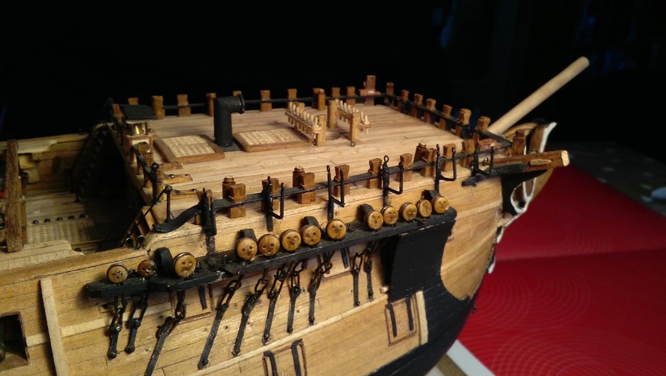
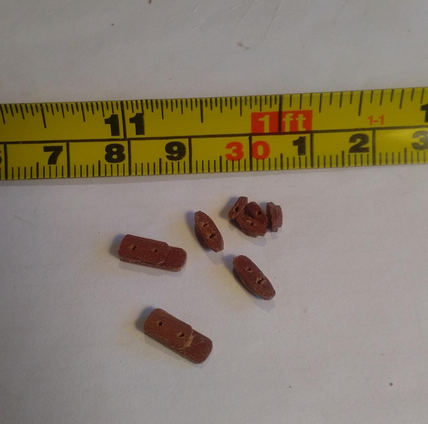
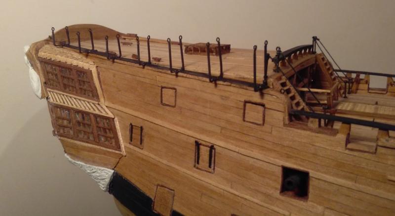
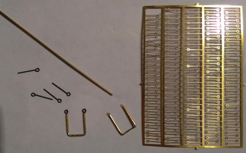
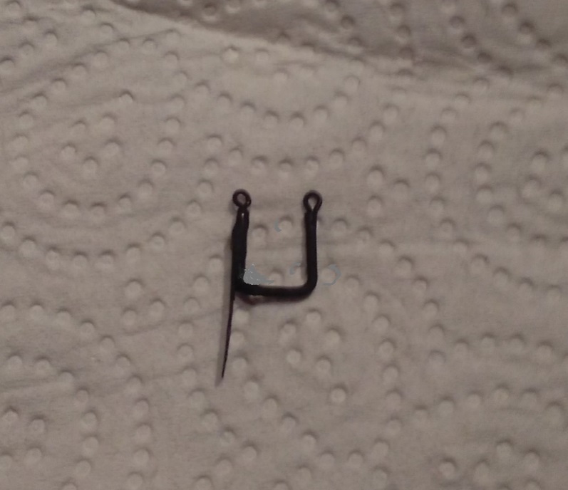
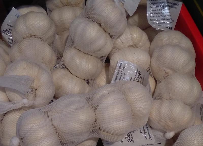
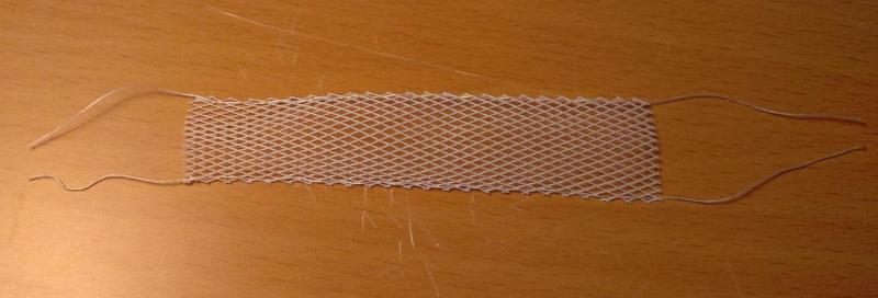
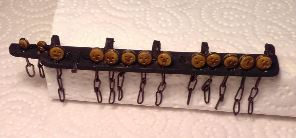
It was about time I had a try at making hammock cranes. There are about 55 cranes on Leopard and there are at least 10 different sizes in varying height & width combinations, so trying to use commercial items was out of the question. Besides, none of the limited options available to buy 'over-the-counter' appealed as their quality and appearance didn't look too good. I wasn't sure how I would go about making them as I have been unable to find any forum posts showing how other builders made theirs. (I'm sure such forum posts must exist -- I just haven't found any.) So, this is what I did >>> These are the first two cranes I attempted. The tube I used was the smallest diameter brass tubing I could find -- 1mm (1/25 inch) outside diameter with an internal bore of around 0.5mm (1/50 inch). I wasn't sure how well that tubing would cope with being bent, but it holds up well even when bent tightly into right-angled 'corners'. The crane on the right was the first, and for the eyelets I used the small etched brass items shown on the R/H side of the photo. At first I opted to use these as I didn't think anything larger would fit inside the bore of the tubing -- but later found that the copper eyelets on the L/H side of the photo were a very snug fit . . . and I preferred the look of these better. The cranes for the foredeck/forecastle are different to the cranes for the other areas of the ship as these cranes are fitted outboard of the topmost hull planks instead of being fitted down onto a rail, as are the other cranes. So, instead of just being regular "U"-shaped cranes, these had to have a vertical 'leg' "welded" on. I've never done a lot of soldering and trying to get these tiny parts stuck together sure provided me with tons of "fun"! Here's a foredeck crane >>> (with not the tidiest soldering) . . . and the 6 stbd foredeck cranes >>> Then it was time for some garlic >>> I had tried to make my own netting but the results were truly awful, and the netting in which these garlic bulbs are sold are about the closest I've seen to the scale I'm working at. This netting, being made of some kind of plastic material isn't keen to hold any creases I try to put in it, but a few spots of white glue helps . . .

- 257 replies
-
- 10
-
-
Thanks Nils, Tom and Mark for the comments, and thanks to the others for the 'likes'. Mark ~ I'm not really averse to a little bit of cheating! Although this is in the "Scratch Build" section there have been a few items that have been 'store-bought' and have been mixed in with the scratch built parts. I estimate that by the time I've finished (if that ever happens!) the scratch built content of the ship will probably be around 95%.
-
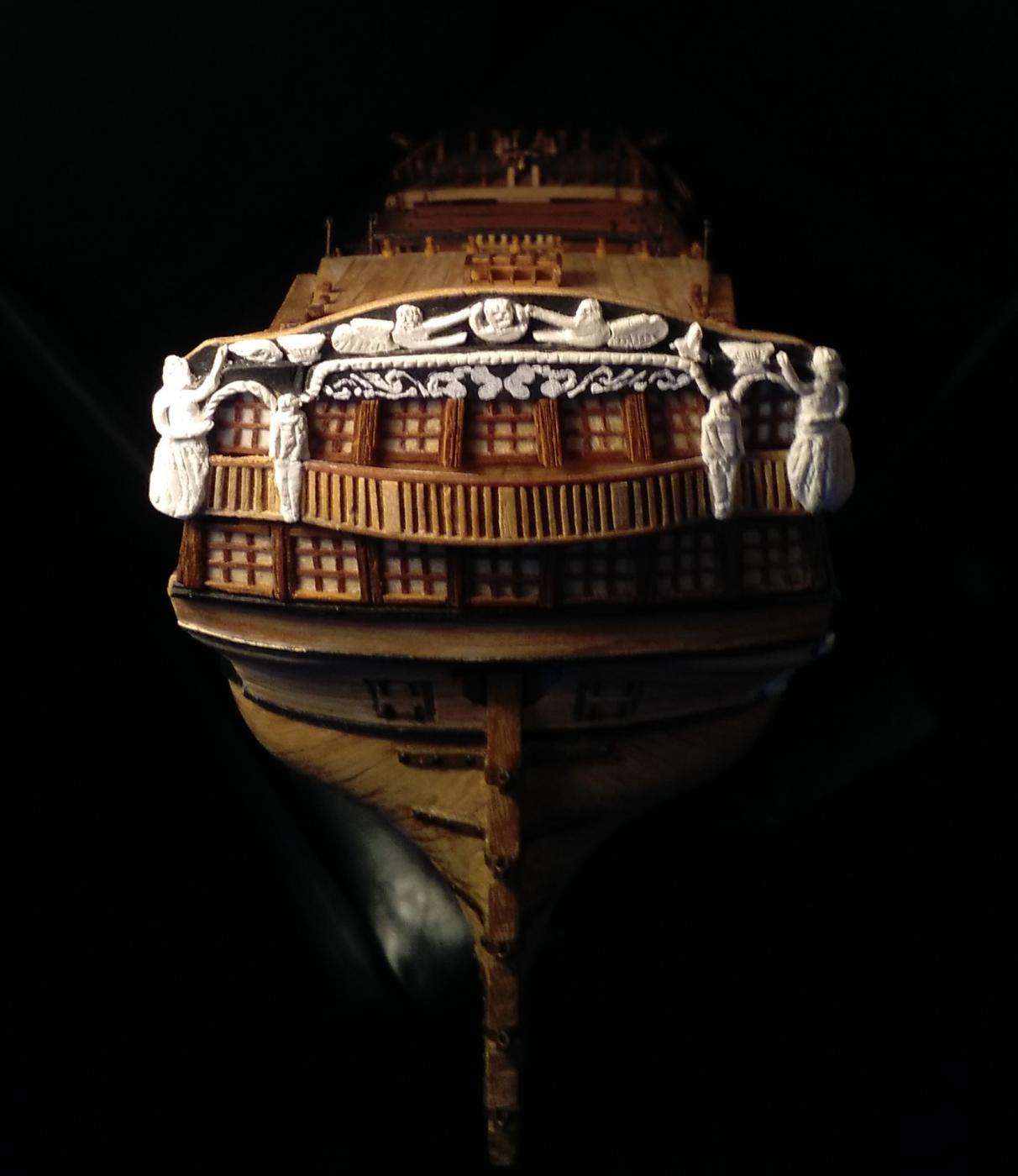
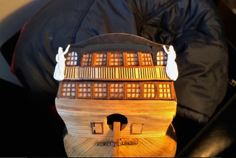
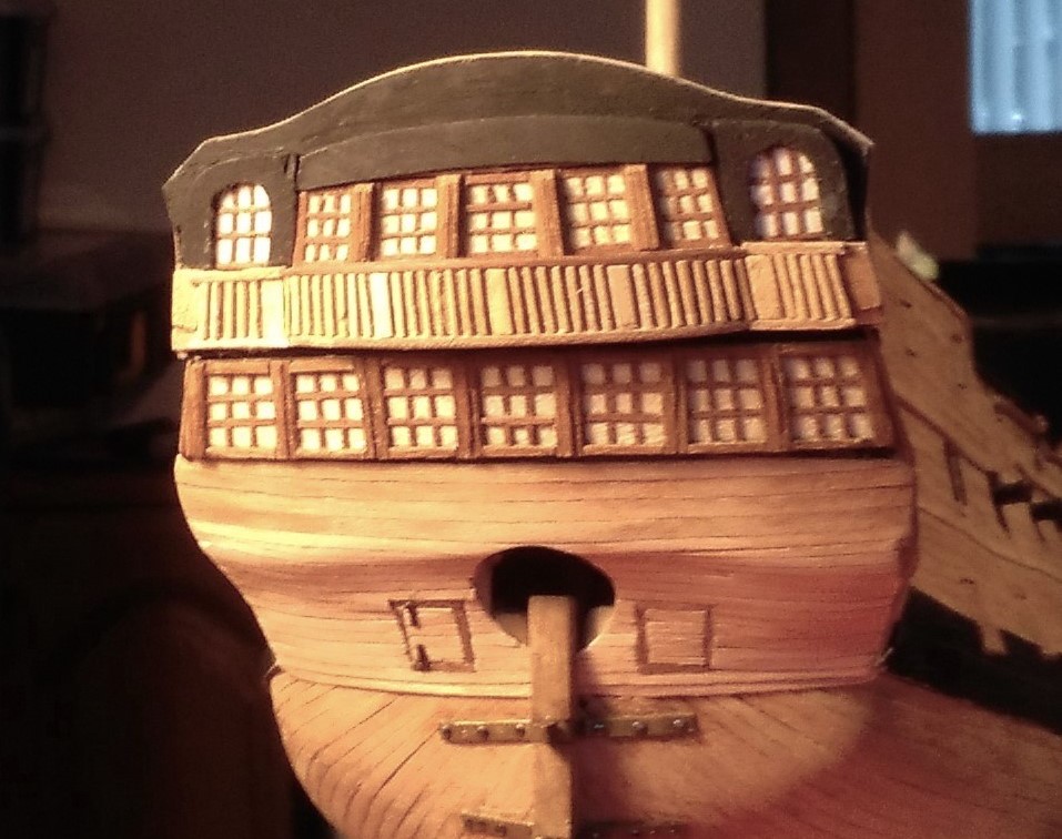
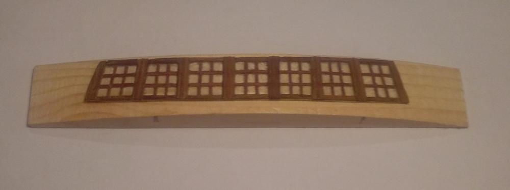
I already said that I had no idea how I would tackle these minuscule moldings/carvings for the lower half of the upper transom. Some parts are less than 1mm/1/25th inch thick and I knew there was no way that I would be able to use the clay . . . so I cheated. I used white acrylic paint on black paper to simulate these carvings, cut the paper to shape and glued it onto the transom >>>
-
Tom, I had also considered the 'oven bake' clay but eventually opted for the air dried version. My main concern with the oven variety was that between molding the shape(s) and getting them into the oven that the shape(s) may have changed or distorted a little - - - and they wouldn't fit where they were meant to go after baking! But I don't know if that would really happen as I haven't used it. I'm really liking your idea of the velvet rope. I'm now off to the rope shop and I think I'll go for the red one! (All I need now is a museum-sized room in which to get it all set up!)
-
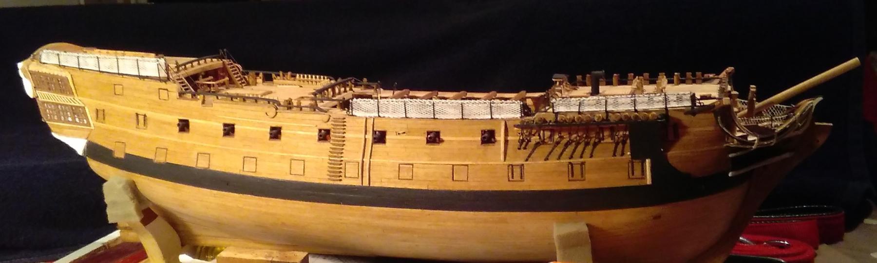
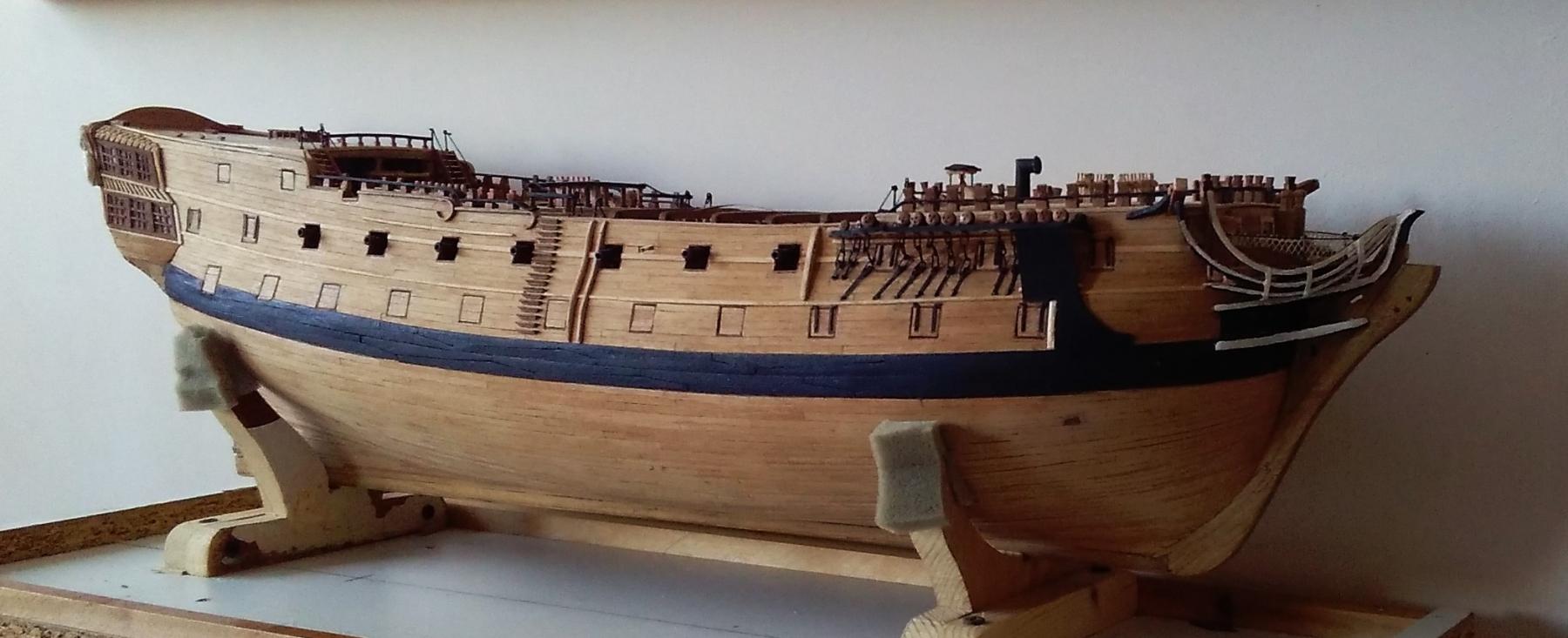
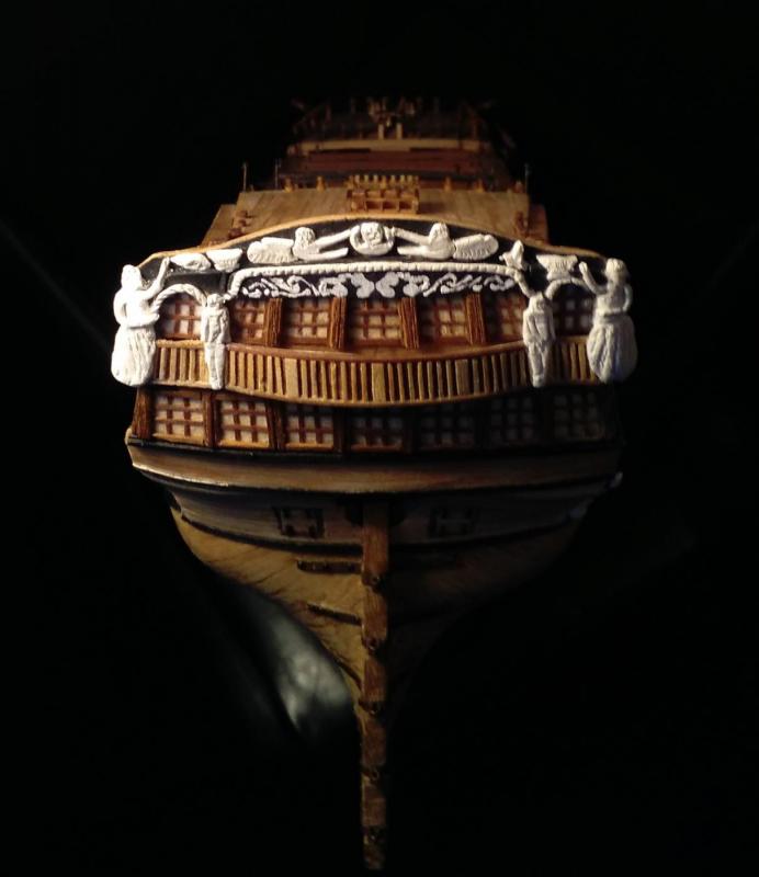
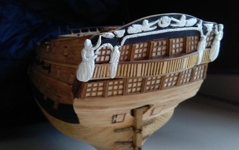
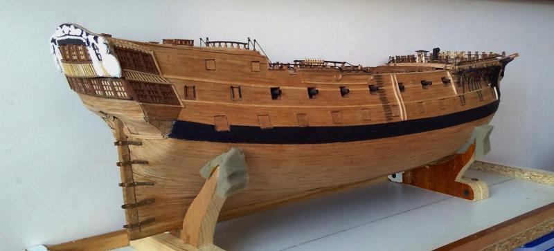
Tom ~ it's coming together . . . it's just that some of the 'bits' aren't as 'happy' as I would have liked them to be. I must admit that when I embarked on this build about 6 years ago I never really gave any consideration to moments such as I have recently encountered! I never really thought ahead about the time when I would have to be getting to grips with trying to make the carvings for the stern. So, here I have arrived at that challenge, and I'm slightly surprised that it hasn't been just as scary as I imagined it would be. Okay, they're not in the same league as the work I have seen on so many build logs here, but for my first attempt they're almost passable . . . at least from a couple of metres away. My first attempt was with the two 'ladies' who occupy the opposing stern corners >>> They're not true carvings in the sense that I didn't carve them out of wood. I used air-drying modelling clay and molded them to the basic shape and tried to scribe such details as eyes, mouth, creases in their clothes etc. I placed the ship 'nose-down' in a large box and supported it with some clothes so that the transom was more or less horizontal. I pushed the moldings into their positions while trying to get them as close as possible to their final shape and left them undisturbed overnight to dry and harden. Carefully prising them off their positions on the transom, it wasn't too difficult to trim them a little with a sharp craft blade. I've already said that I don't want strong/garish colours, and while I had thought of something like a yellow ochre or pale gold colour, I eventually decided to use them in their 'out-of-the-pack' colour of white. Some of the details are so minute that I felt that any addition of paint would probably obscure tiny eyes, mouths etc. Here's another brutal close-up of all the 'major' carvings for the stern. I've called these ones 'major' as the carvings that go immediately above the five upper windows are truly tiny. (I really have no idea how I will tackle these, and am thinking I might make-do with what's already on the transom???) There are still 2 'major' carvings to go at each corner below the quarterdeck level. >>> Over the last umpteen postings there have been nothing but these brutal close-ups that show up all the imperfections (and even worse things!), so, just for the fun of it I'm going to post a few photos showing 'the whole picture'. My original intention in building this was to end up with a ship that has the general appearance of a sailing ship, and when I look at it from a short distance I'm reasonably pleased with it - - - it's just the details that get to me! Okay, enough of the lamentations, here are a few pics >>>

- 257 replies
-
- 10
-
-
Other 'stuff' done recently. This fore channel was made about 3 years ago and has been living in 'the box' since then. >>> It was time for it to meet the ship >>> . . . and fitted with the board that protects the hull and the forward chainplates from the anchor flukes. The best information I have is that is called the 'billboard' ~ but maybe someone knows differently??? >>>

- 257 replies
-
- 10
-
-
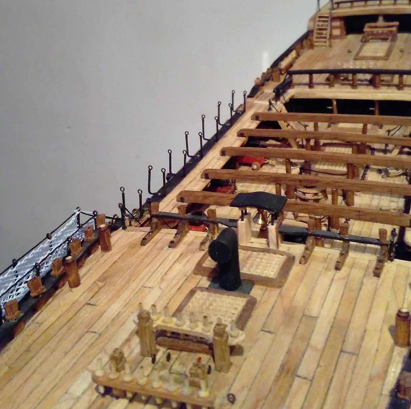
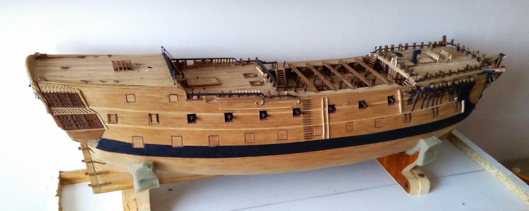
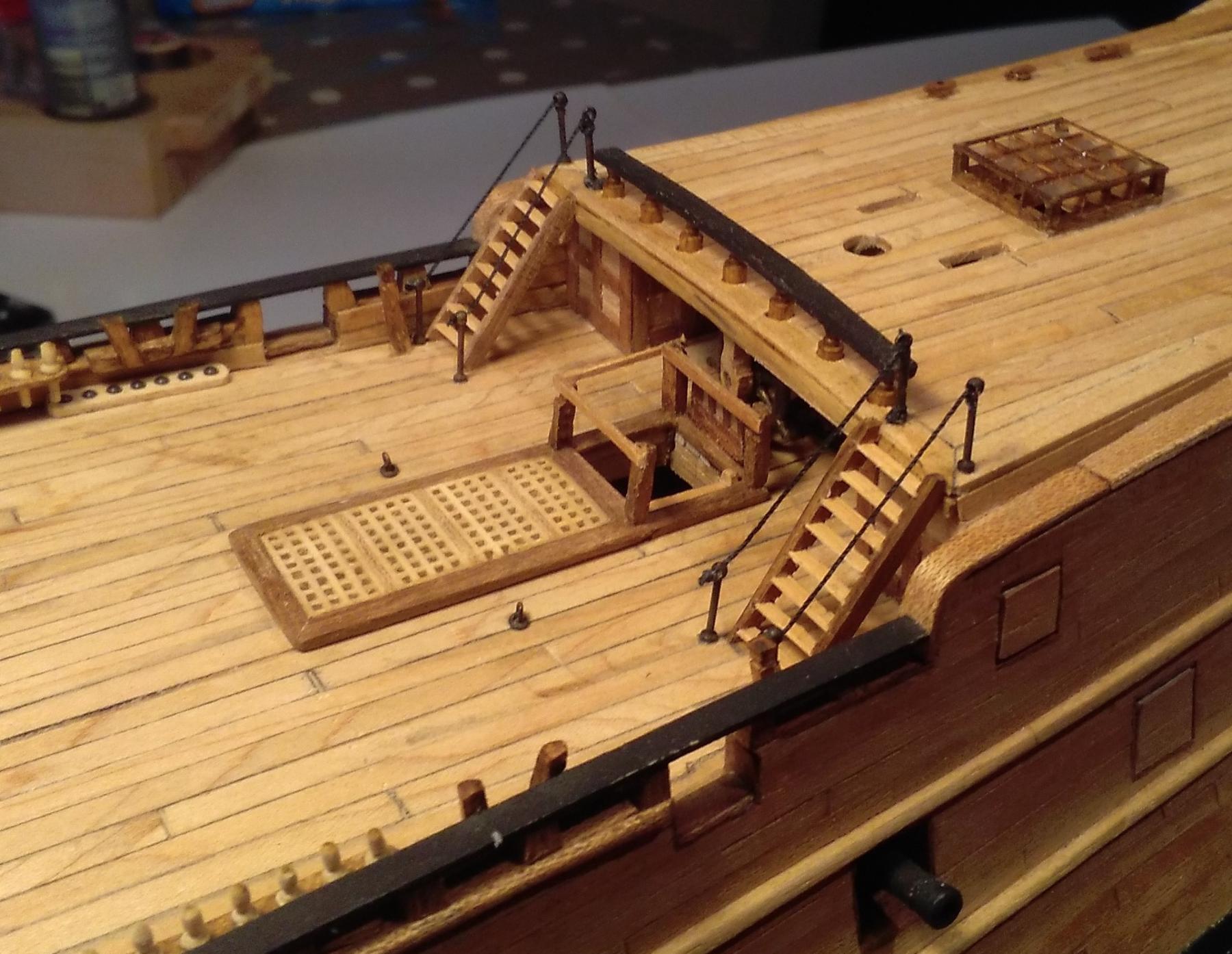
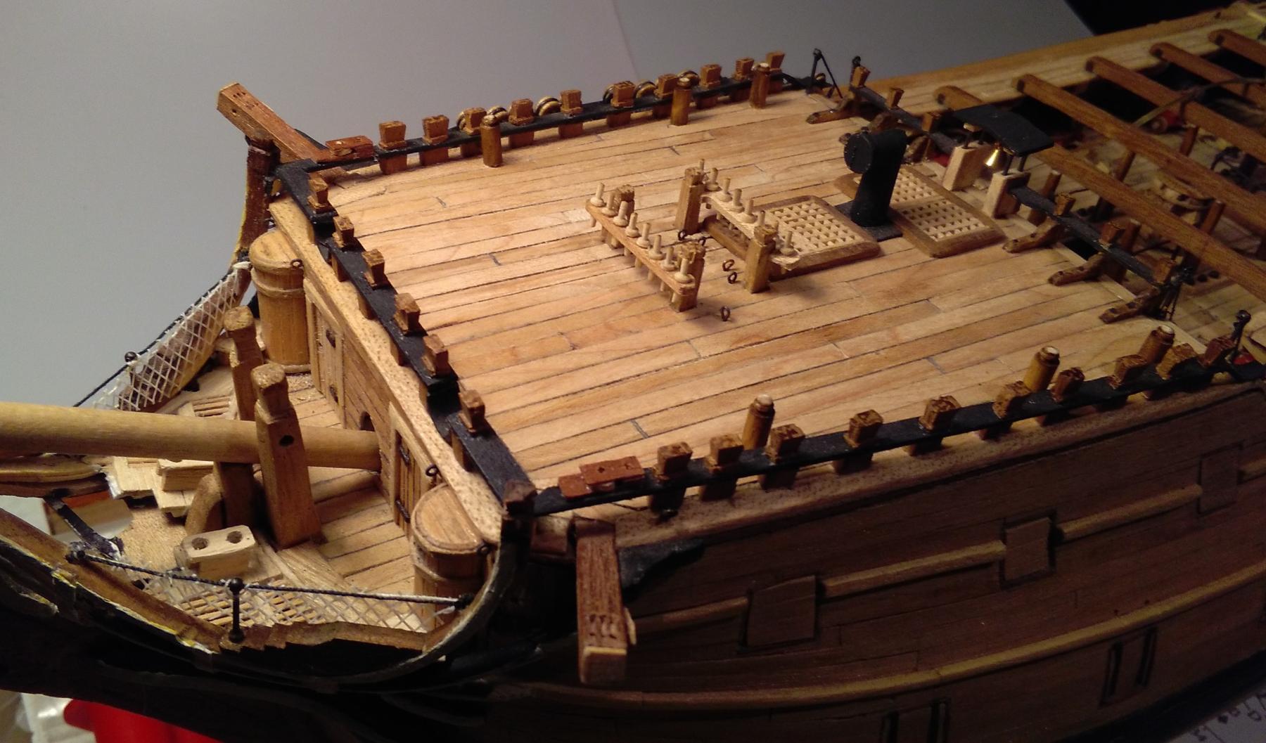
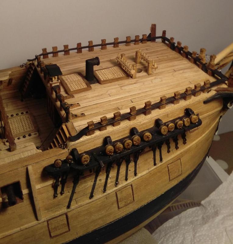
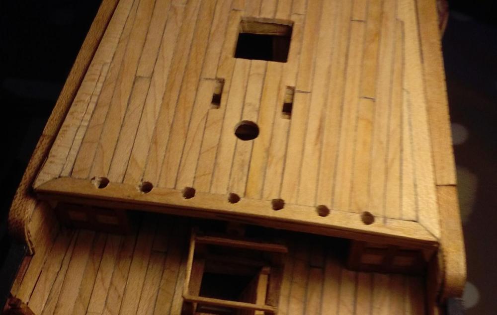
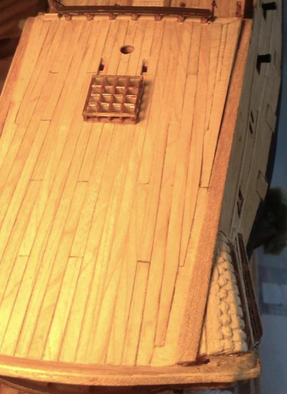
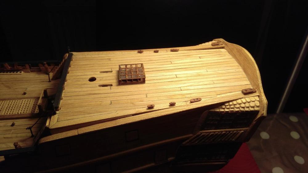
Right now the stern area looks like this while I try to prepare myself to have a go at those carvings >>> Meanwhile, other smaller (and easier) stuff has been getting added around the ship. That square hole in the poop deck needed to be capped >>> Two snatch blocks and a collection of deck cleats for the poop deck >>> . . . and fitted >>> Eventually, the poop deck ladders got both handrails >>> As did the foredeck ladders >>> The foredeck eventually got its' kevels, snatch blocks, deck rings etc. >>>


- 257 replies
-
- 10
-
-
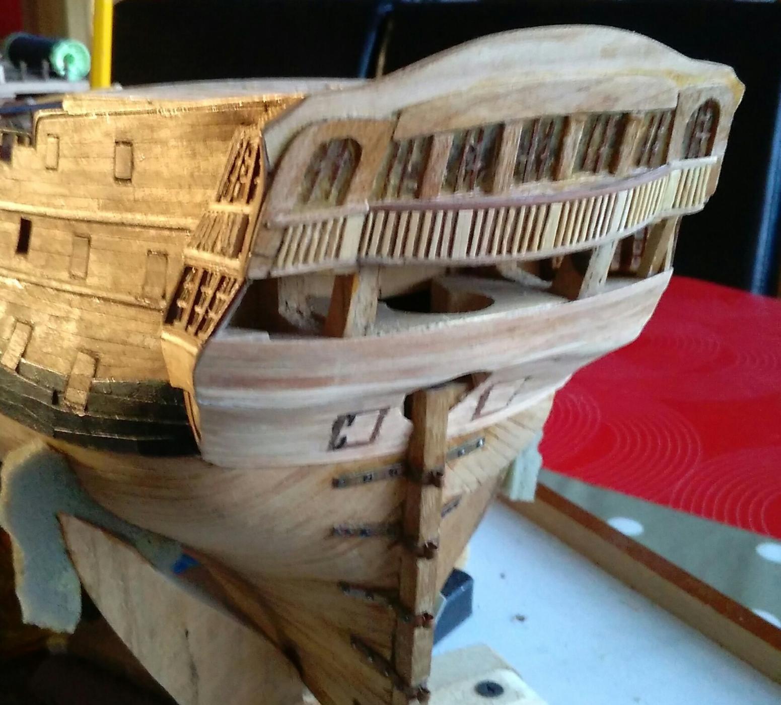
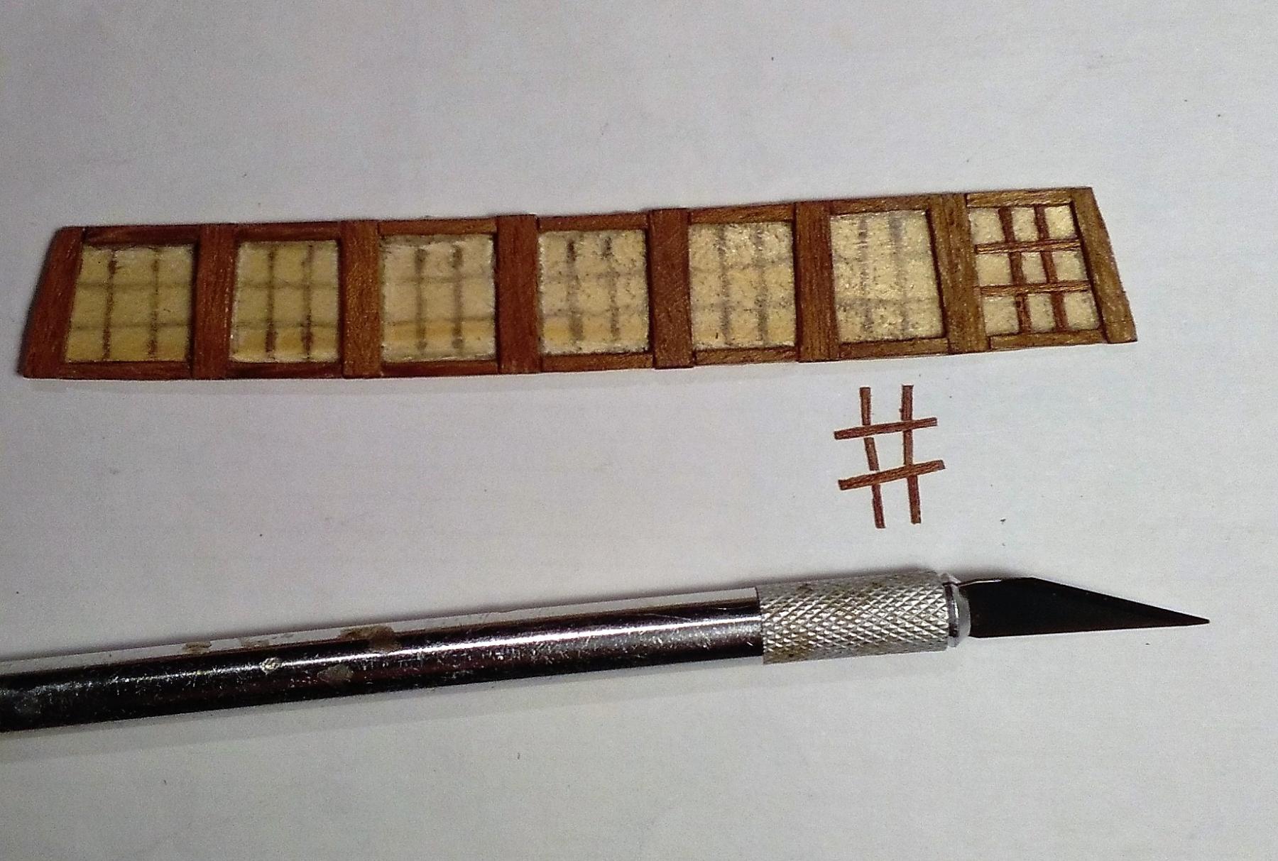
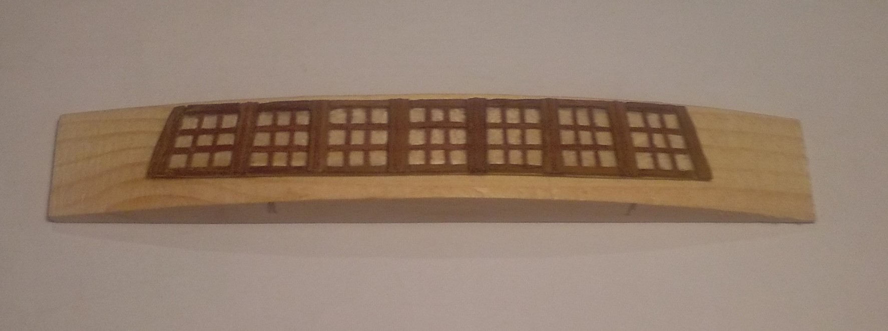
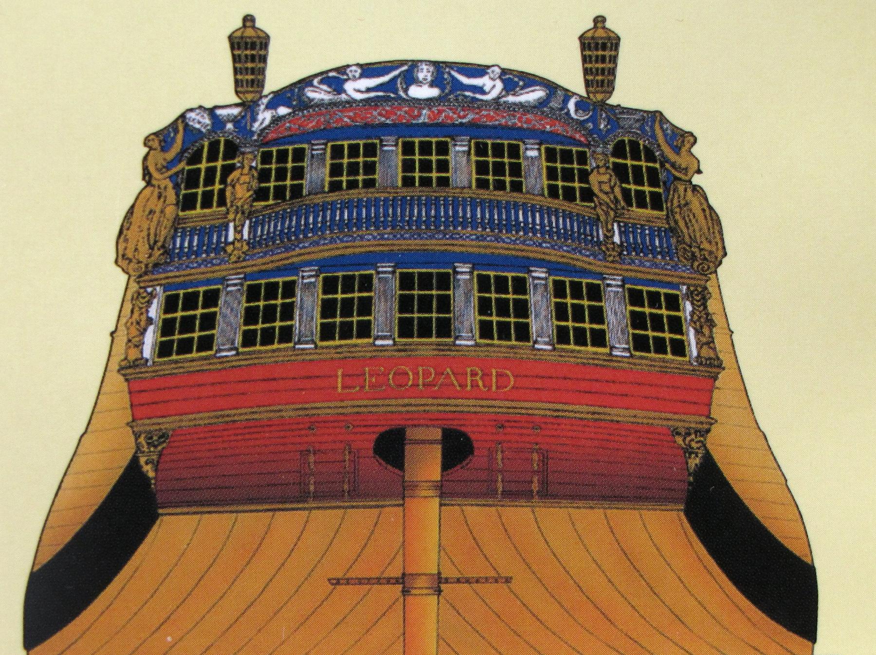
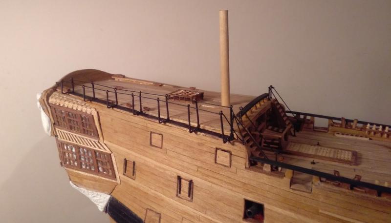
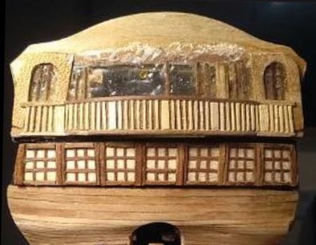
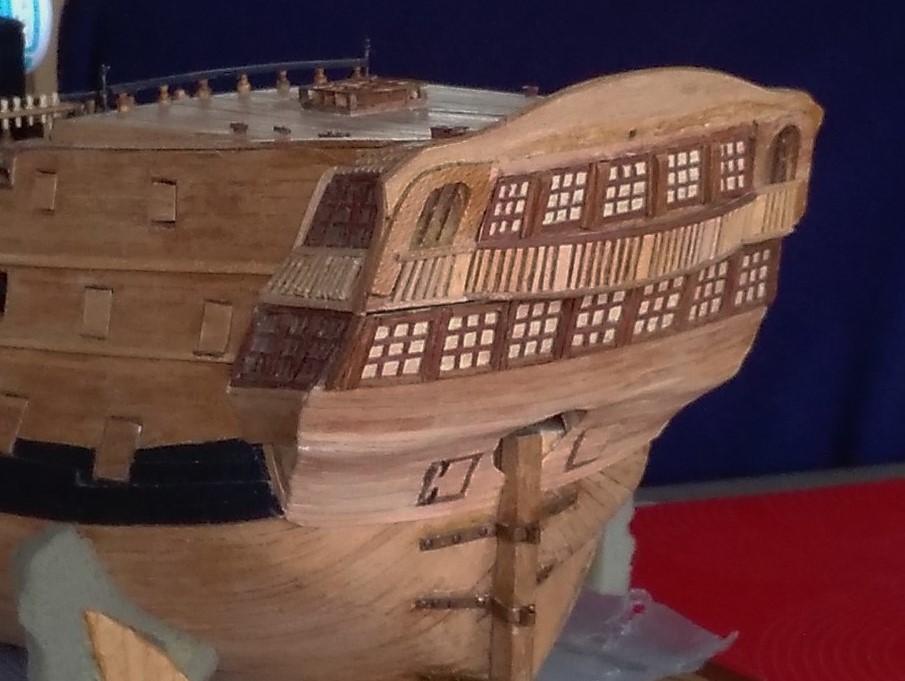
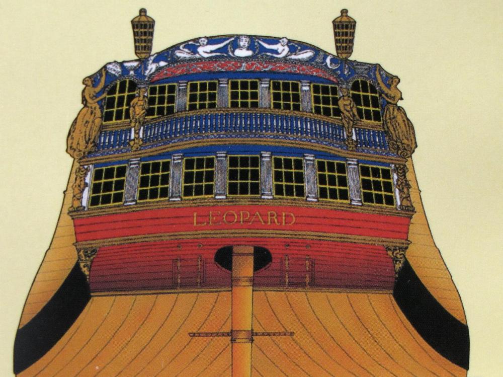
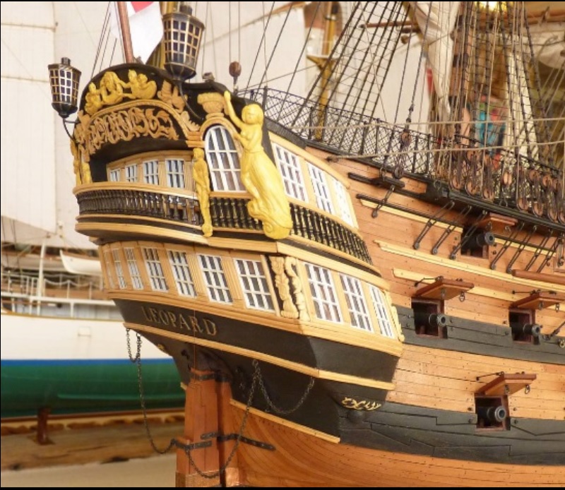
I'm thinking of re-naming my ship as H.M.S. 'Nemesis'. A few months ago I had something of a Nemesis when I was attempting to get an acceptable result with the head timbers . . . but for more than 3 years there has been a historic Nemesis awaiting further attention. For over 3 years the stern quarters have been languishing there, looking rather desolate. This is what lurked there >>> At upper deck level there was just that gaping hole that stretched from one side to the other. At quarter deck level I had attempted to create lights/windows using clear polythene masquerading as glass, and thin mahogany strips as frames/mullions. These windows didn't look good back then, and when I recently re-visited the area, they looked even worse. They had to go. Before demolition I had a try at making something to cover that gap on upper deck level >>> I abandoned the polythene windows in favour of light coloured wood with thin mahogany strips again for frames/mullions. >>> The pic above showing the upper deck windows fitted, and the partial demolition of the 5 inner Q/deck windows. The 2 outer Q/deck windows remain and will need some attention to get them to some kind of acceptable appearance . . . what that 'attention' will be, I'm not sure yet ??? The photo also showed the horrible Q/deck polythene which still had to be removed at that stage. The stern quarters at the present time >>> Since I began this build until now I haven't been very clear as to a 'colour scheme' for the stern, and until just a couple of weeks ago the following illustration was all I had >>> That was just far too garish for my taste . . . I'm hoping for a far more neutral look for the ship, and while I know there is an amount of decoration at the sharp end as well as at the stern, I want to keep it a bit low key compared to the illustration above. A couple of weeks ago I found the look that I would ideally like for my stern >>> Unfortunately, I have already gone the opposite route in that I went for light coloured windows and dark frames, but this photo has given me a degree of direction for where I go from here. . . . then, of course, there is the adventure of doing all those carvings! . . . I have no experience of doing any carving of any kind, so you may like to check back here in another 3 years or so to see what's going on then! *** For the final photo above of the Leopard's Stern, credit goes to Larisa Rumantseva, Ukraine. ***


-
Hi Tom, Just back from holiday and catching up with your build . . . and it's looking very impressive. You seem to be making quite rapid progress with these frames and bulkheads, and they're looking very crisp and precise. I'm really looking forward to seeing this 'half and half' model. (I'm very keen to see what the inside of my model SHOULD look like!) Jim.
-
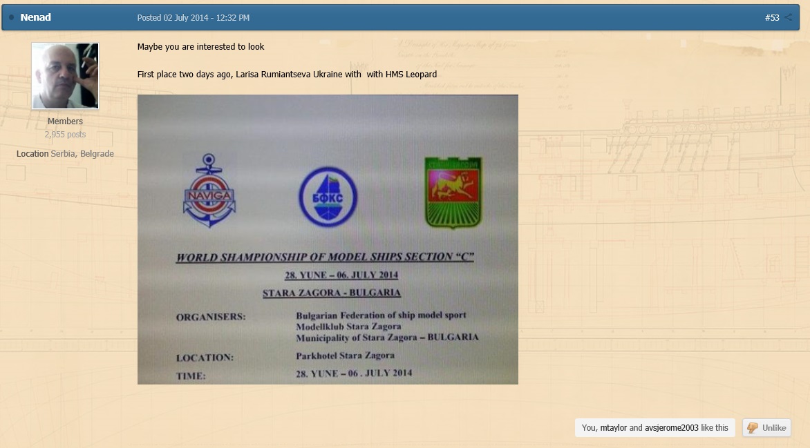
MMDD ~ back in 2014, on my own build log of Leopard, Nenad posted about Larisa's Leopard >>> At that time I could only find a couple of photos of her Leopard but your photos are great. I wish I could have found these photos back then . . . they would have been a great help to me in my attempts with my own build. If you have any more photos of Larisa's Leopard I would love to see them. Thanks.

-
Looking great Tom! . . . I'm looking forward to seeing it once you've got some "flesh" on it! . . . I'm sitting here, waiting patiently!
-
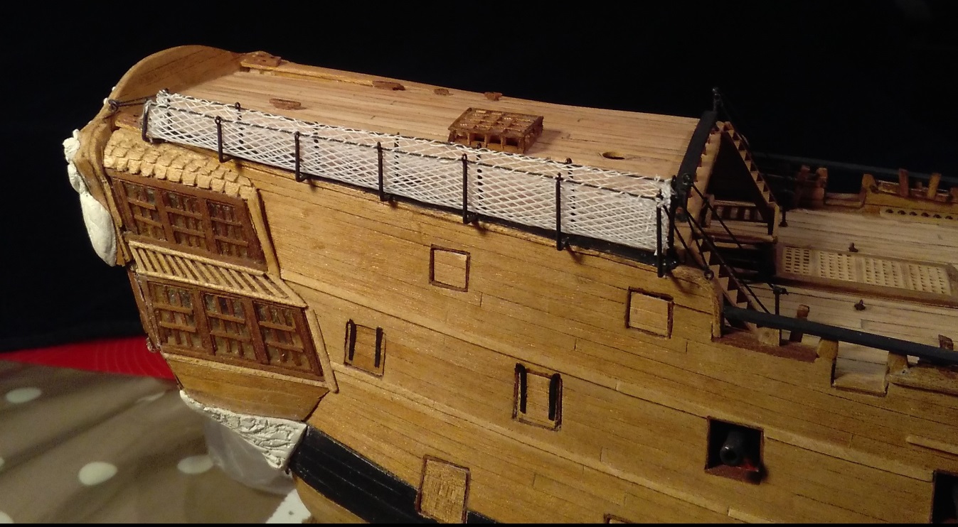
RedDawg, Maybe I should have explained how the body plan relates to real bulkheads. In the plans you will already have a copy of the body plan as shown below. I've drawn a red vertical centre line on the plan, and this line is critical when drawing your bulkheads/frames. The plan only shows "half-bulkheads". The ones on the left side of the centreline are the bulkheads aft of mid-ships to stern, and those on the right are for the ones forward of mid-ships to the bow. As the plan only shows "half-bulkheads" I had to cut out a half for each bulkhead and from there transpose onto the wood that I was using --- as shown on the video in the earlier post. (This meant that I had to have a photocopy for every one of the 25 or so bulkheads ~ and a nice pair of sharp scissors to cut them out!)