Bluto 1790
-
Posts
324 -
Joined
-
Last visited
Content Type
Profiles
Forums
Gallery
Events
Everything posted by Bluto 1790
-
 Tom, don't worry about posting on this topic . . . the more the merrier! RedDawg ~ I don't know if this will be any help, but I did a short video of how I drew my bulkheads before cutting. Even if you propose to do a framed model I would think that you would be able to use the same (or similar) procedure with a bit of modification, for drawing the outline of frames instead of bulkheads. If my memory serves me, there were about 25 bulkheads and on a framed model there would be more than twice that amount of frames. While the frames aren't detailed, I expect that you would be able to calculate from the plans how to create the frames. Here's the video >
 -
Tom ~ I see you're proposing to build at 1:85 . . . that's just a tad smaller than mine! I'll definitely be watching your build log. Only thing is -- you should have built and logged your Leopard before I started mine so that I could have learned from you! I've been looking at your Constellation build log ~ very nice! . . . AND - you're building a P.O.F. model. I haven't seen a frame-built Leopard. Now, don't let me hold you back here --- you need to get building and logging here!
-
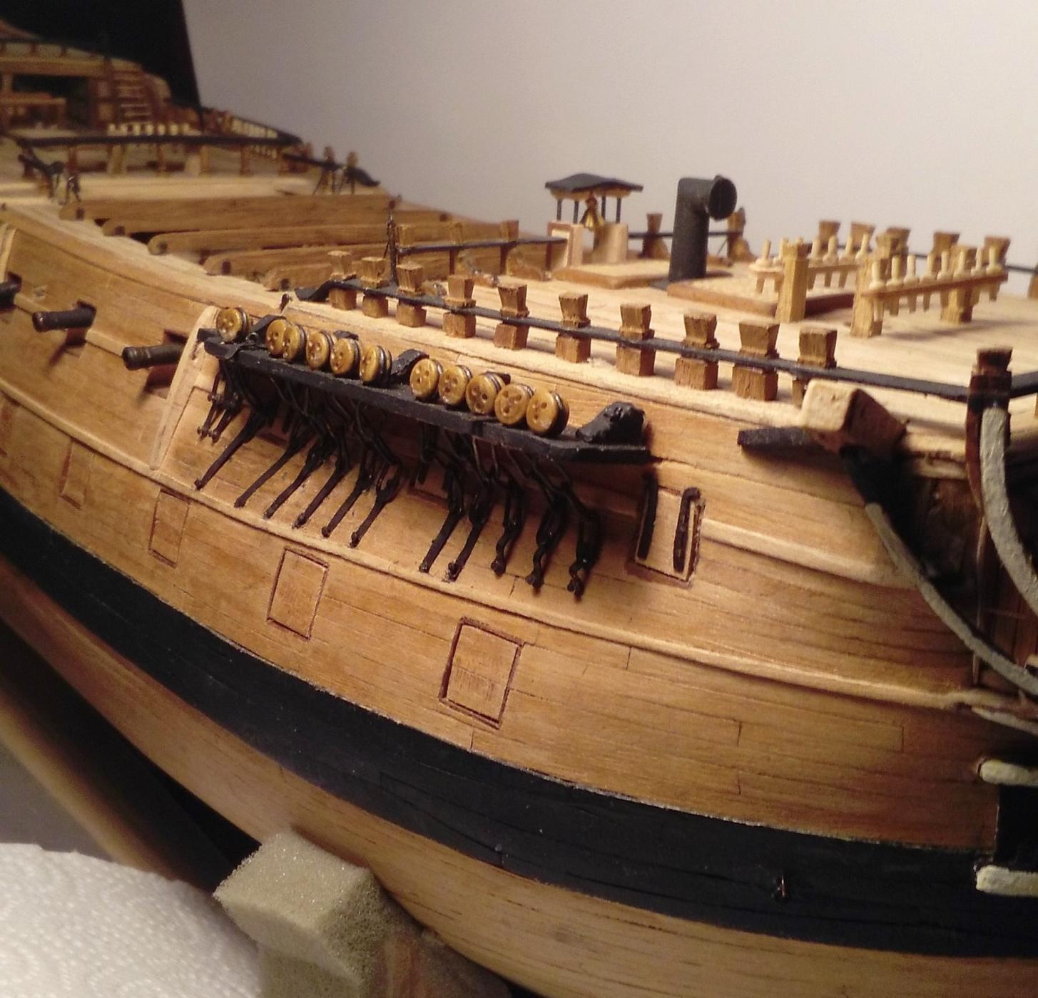
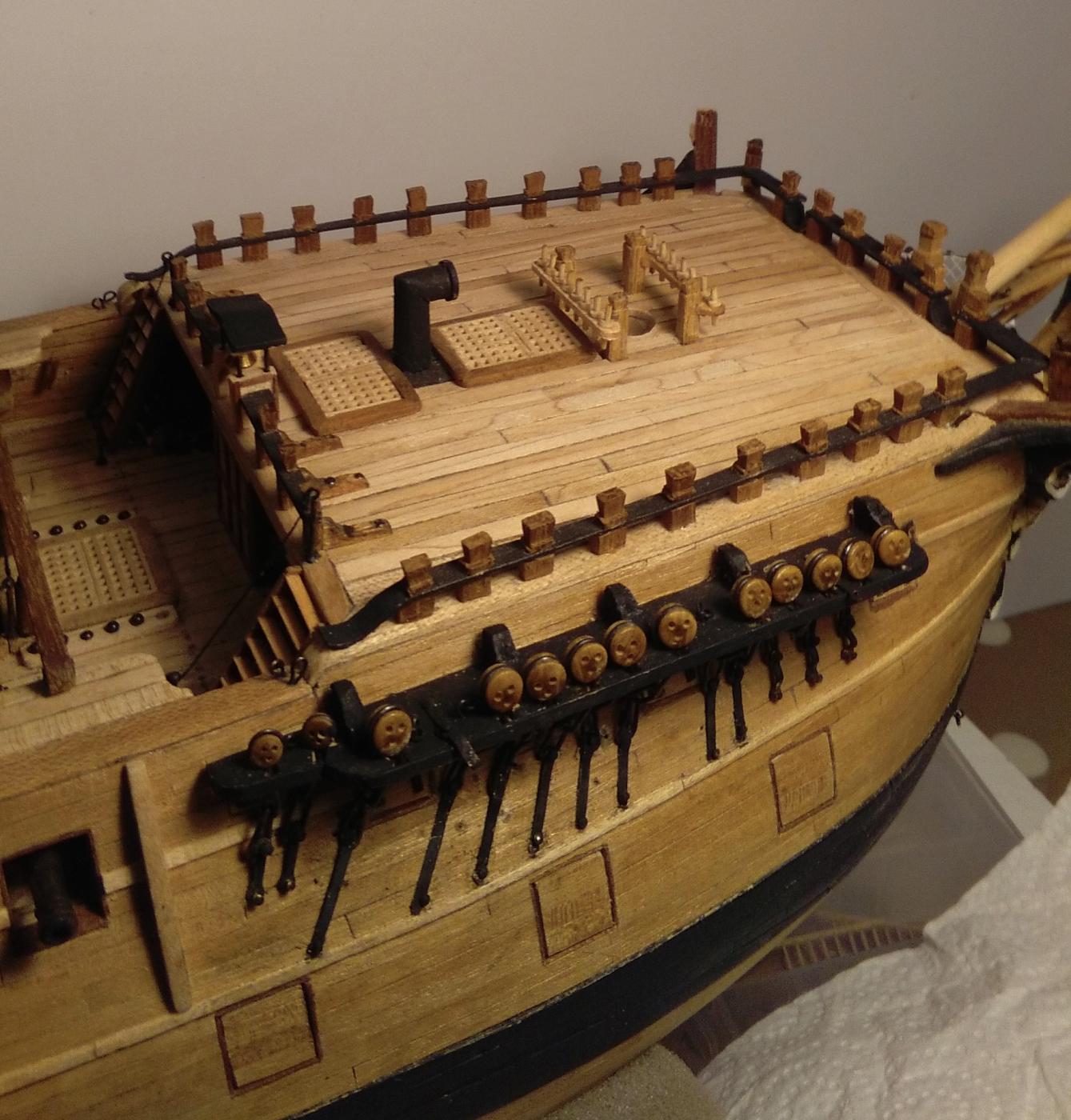
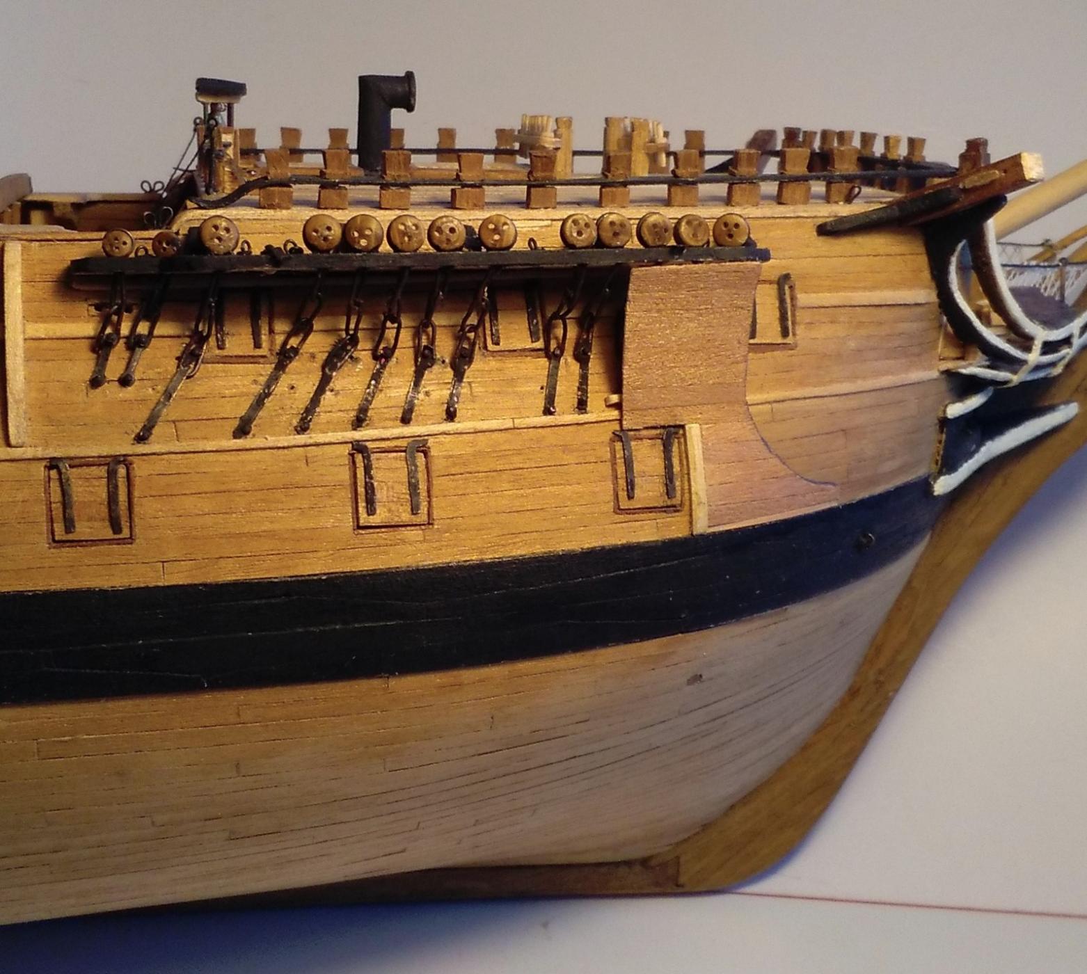
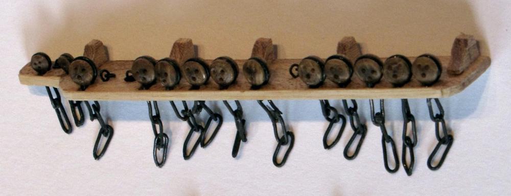
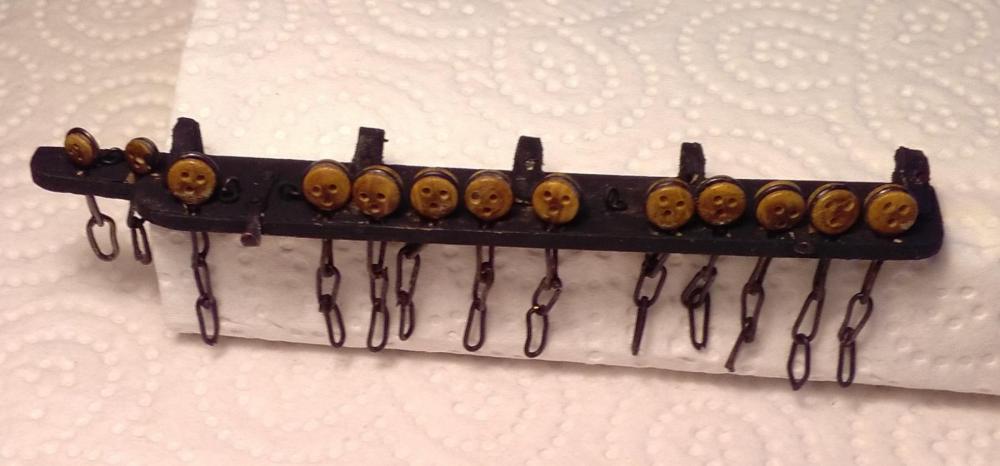
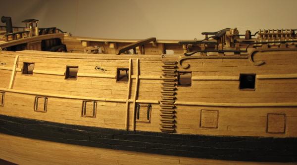
Thanks for your comments, Mark and Tom. Tom ~ it's good to see another 'Leopard Man' on board! I'll also be watching your build log with great interest and I'm looking forward to your log getting under way. Have you decided at what scale you'll be building your Leopard? If you've read the earlier part of my log you'll have noticed that I've said I would have liked to have built at a larger scale than the 1:80 at which I'm doing this one. O.K. while I'm here I'll post an update. Long, long ago, when I was slogging away at the hull planking I did a few diversions to escape from the tedium and one of these was having a go at making the fore starboard channel. It must be around three years since it has been hibernating in 'the box' and it looked like this > It came out of the box recently and got a coat of black paint > Then > . . . with chainplate guard (I expect it had a 'proper name' but I'll just have to call it "chainplate guard") > Before I fitted that channel I eventually got all the timberheads finished on the forecastle > The other 5 channels are calling me, as are the hammock cranes and netting but there are still a few other things around the various decks to get sorted out first.


-
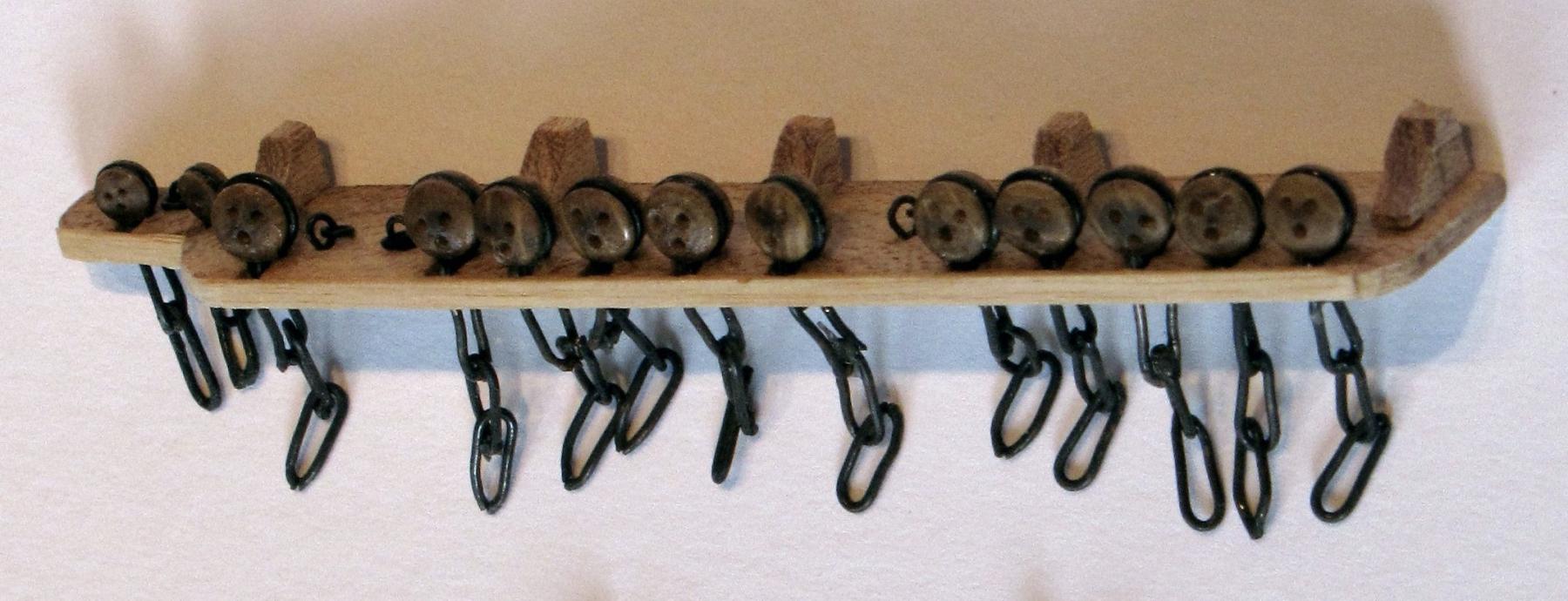
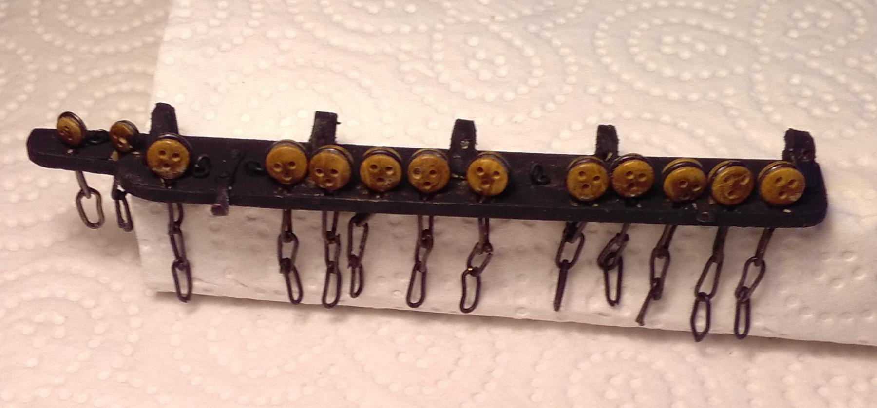
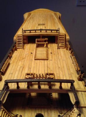
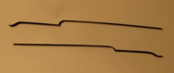
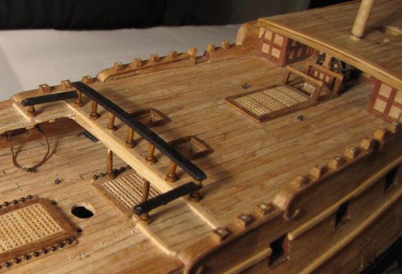
Before that almighty challenge ~ "The Rigging" arrives, there are still plenty of miscellaneous tasks to be done around the various decks. Of the six 'exposed' ladders there have only been two of them fitted for such a long time ~ the two from the waist up to the quarterdeck at the aft end of the gangboards. These two had been done by hand before the arrival of my milling machine but the final four were done on the machine. The two forecastle ladders >>> Before the poop deck ladders, the poop rail came along >>> Then with both ladders fitted >>> . . . and now I have the 'interesting' challenge of how to create something that will pass for hammock cranes ~ or, rather, more than 50 'somethings' that will pass for hammock cranes . . . and just to make it even more interesting -- there are so many different sizes of them as well!


-
Hi Frankie, Thanks for your comment. I'm not big on reading novels . . . but I have read Desolation Island, and all the way to the end!
-
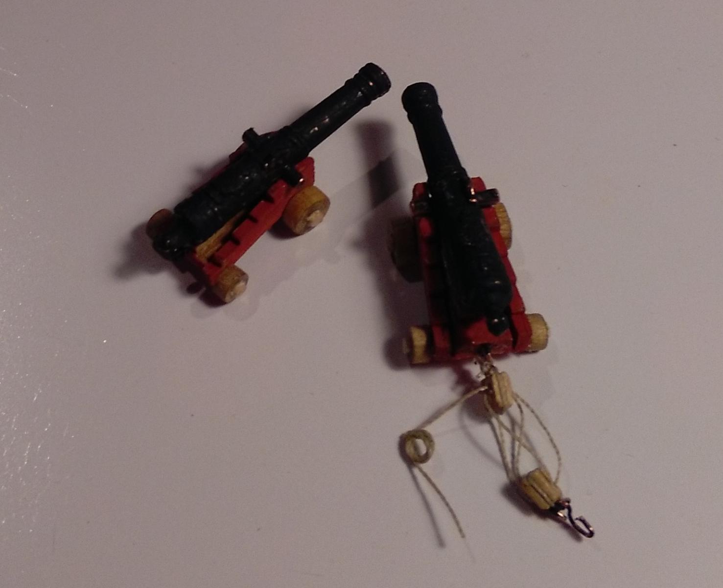
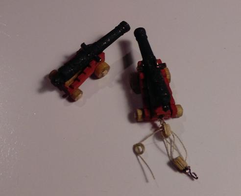
Time for some more work in the waist: The port side ladder at the aft end of the gangboard was fitted. Preparation of the 10 gun carriages worked out at something like 1 carriage & rigging = 2 night's work, so about 20 night's work for them alone. Here are a couple >>> I previously said I didn't want to be hampered by the skid beams while attempting to get the guns in place then fiddling with the rigging so I fitted 1 gun/carriage & rigging to each side then fitted a skid beam and worked along the waist like that. So, for several months there had been one skid beam there all on its own ... Then there were . . . >>>


-
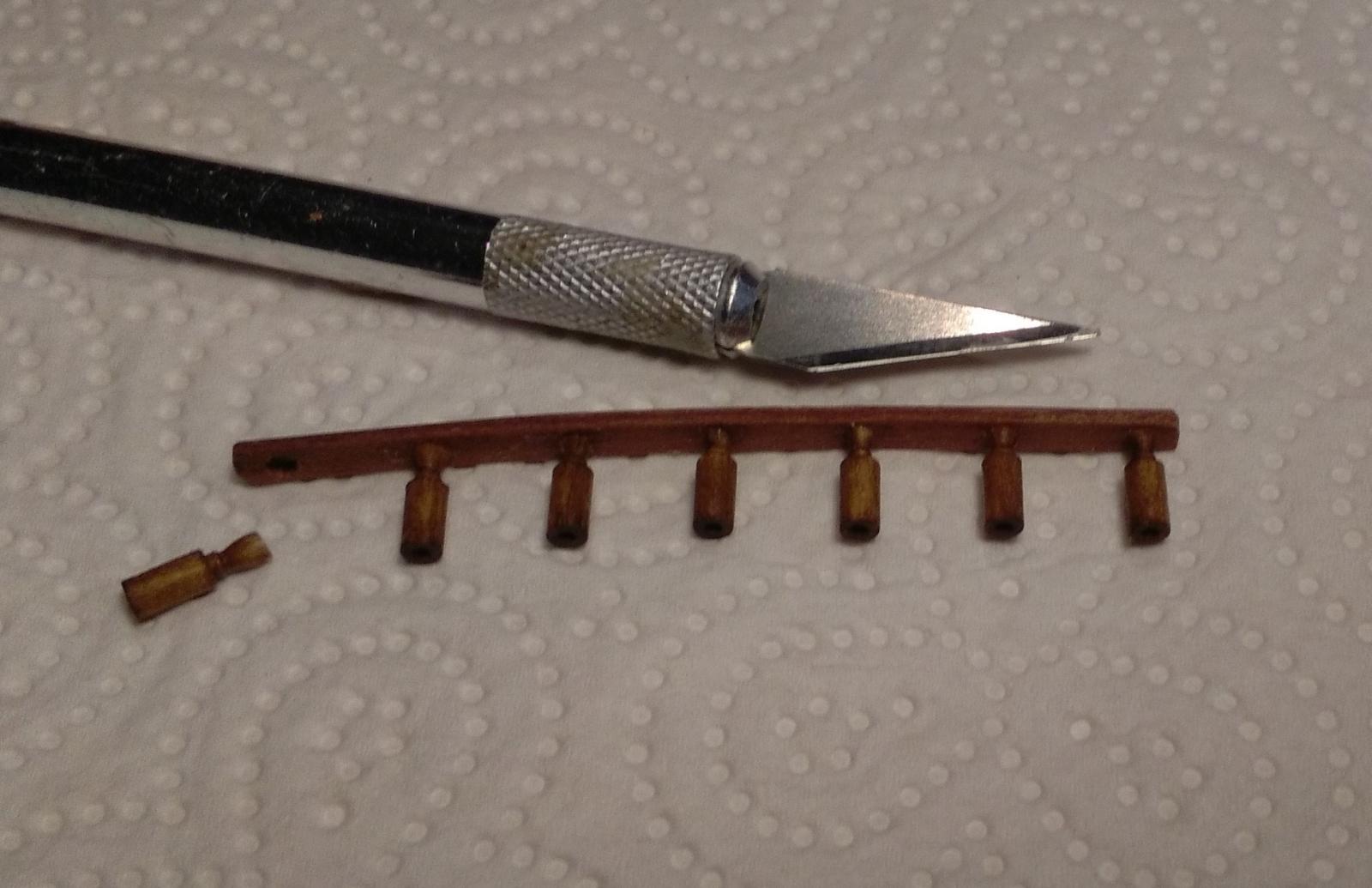
Progress report: --- or rather, lack-of-progress report. The forecastle has been close to being more or less finished for a time. I still had the 'tops' of the timberheads to fit all round plus a few eyebolts and kevels. These tops are only about 3mm (1/8") in height and are ideal 'fodder' for the milling machine. So, since the fo'c'sle aft rail required 6 'tops' they were the first to be done as they are slightly different from the 'tops' on the other 3 rails. They worked out OK and with the thinned down belaying pins for the forebitts here they are >>> The timberhead tops for the other 3 sides are slightly different and there are 26 of them. So, back at the milling machine and these tops were about 75% complete when my milling machine suddenly died. Well, I think it was murdered as there was an almighty BANG like a gunshot which tripped out the entire domestic ring main of my house and workshed. After I re-set the mains the machine remained dead and right now is back with the supplier . . . and my timberhead tops patiently wait to be finished. I will leave them for the machine as I just couldn't reproduce the accuracy and consistency that the machine can deliver. I can use the machine to cut them all to exactly the same height instead of doing the job by hand and only achieving "26 timberheads that are only approximately the same dimensions." Only a few other small jobs have been done and of these, only one gun with its carriage and the starboard quarterdeck/gang board ladder and handrails have been fitted >>>


-
Thanks to those who clicked the 'like' button and to Frankie and Mark for your comments. Mark ~ thanks for the link you posted. I've only had the milling machine for about 3 months and I wish I had had one much earlier in the build. Frankie ~ first, thanks for liking my build! You said that I "appear to think that I'm not as good a builder as some people." Well, you're right, and it's not for no reason that I feel that way. There are so many incredible build logs on the forum by so many fabulous builders (none of whom will I mention as I wouldn't want to miss any). I'm just blown away when I look at some of these build logs and see the perfect detail that goes into these ships. But --- you're also right about the scale at which most of these models are built and I would have been happier to have started a project at 1:48 or at least 1:64. When I started this build it was my intention to finally have a model that will at least have a passable resemblance to the real thing, and as it stands at the moment I'm quite pleased with its general appearance - it looks fairly acceptable at about 2 metres distance! It's the detailed parts of the ship that sometimes cause me to be disappointed with my results . . . but I'm old enough and ugly enough to realise that I can live with the limits of my own skills.
-
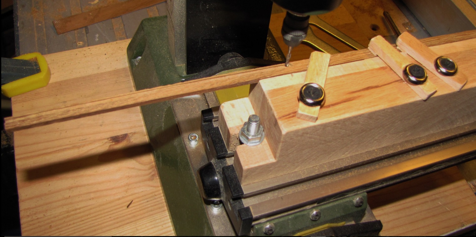
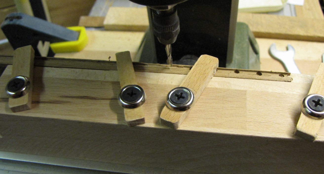
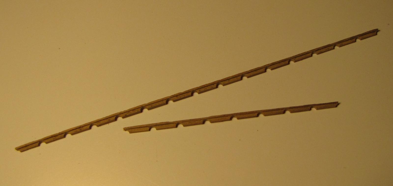
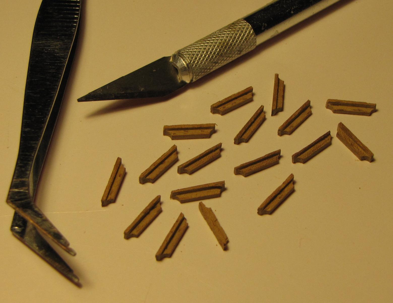
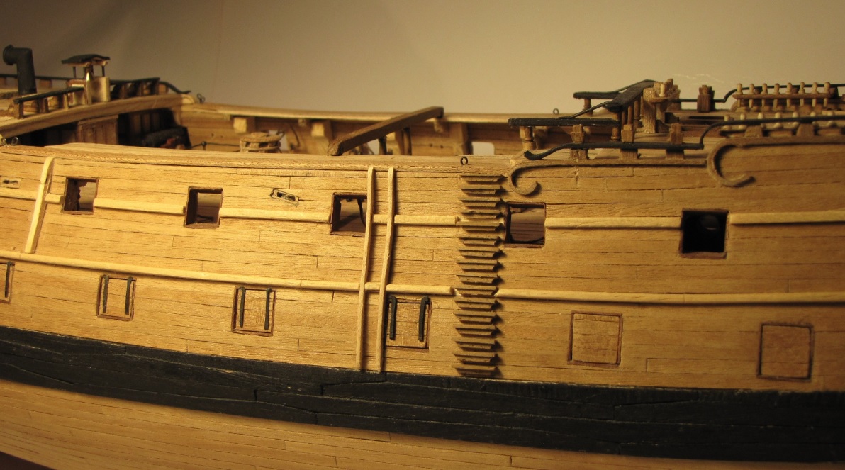
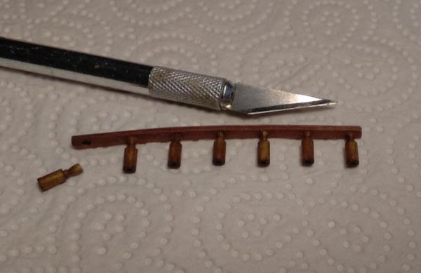
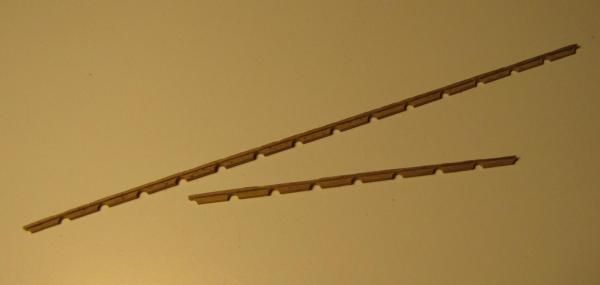
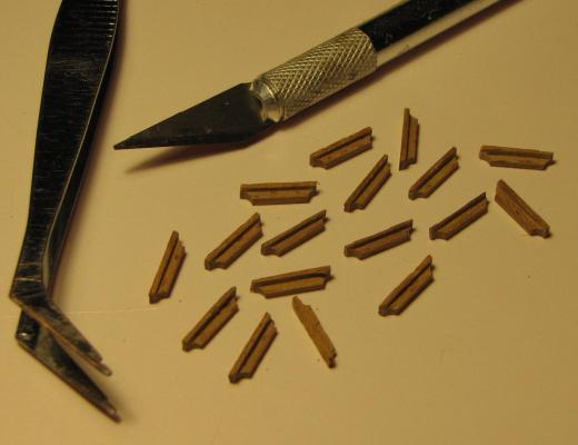
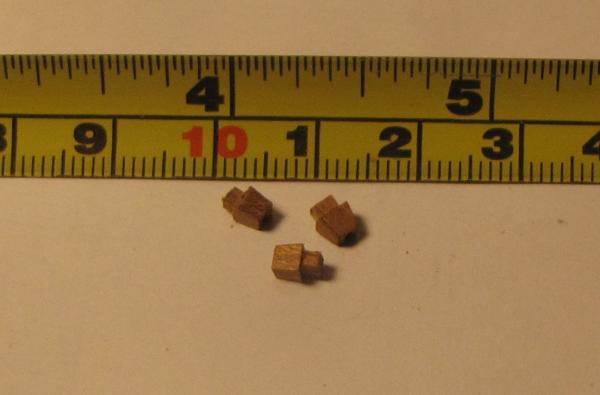
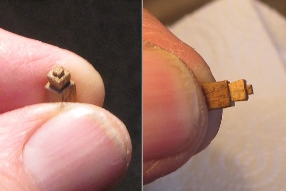
When I started this build (over 5 years ago) it was my intention to finish up with a fully rigged ship. Right now at this time I’m not sure if I’ll ‘progress’ that far, but at least I want to have a completed hull model. There are still so many small parts to be made and fitted to the hull and next task I chose were the boarding steps. I don’t know how all you proper model ship builders make these steps and before I recently got a milling machine I had imagined that I would have glued a narrow piece of timber to the underside of the step to achieve that ‘two-tiered’ appearance, but instead here’s how I’ve done them --- In a 2mm thick piece I milled a reveal at about 0.75mm below the top edge of what will be the step . . . probably better seen in the pic below >>> (each length had to be milled in 2 stages as the 'working travel' of the work table is only 134mm. In the pic the first half has been milled and the workpiece has been moved along the table ready for the 2nd half to be milled. The first half wasn't milled in 'mid-air' ! ) I used 2 pieces of about 190mm in length in order to obtain enough steps for one side of the ship from each piece then drilled 3mm holes at 11mm centres below the top of the ‘step’ along the entire length. These holes ensured a constant length of 11mm for each step and also provided an arc shaped cut-out on the underside at each end of every step after they were finally cut out >>> Here’s one of the 190mm lengths after being milled to width (in 2 pieces after it collided with a ship builder’s hand) >>> . . . and cut into individual steps >>> . . . then, on the ship >>> All the steps shown in the pics above were milled to final width and they are all more or less identical. However, without thinking it through, I didn't use the milling machine at first to cut the other strip of steps to width. Instead, I started to cut them by hand and after about 5 or 6 I realised that it was going to be difficult to get them all a uniform width so I finished off the strip in the machine . . . but now I don't have a 'collection' of identical steps for the other side of the ship . . . . . . so, it's back to the milling machine with a new 190mm length to start over again . . .


- 257 replies
-
- 13
-

-
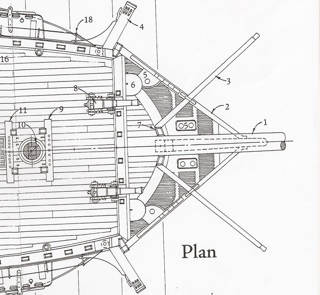
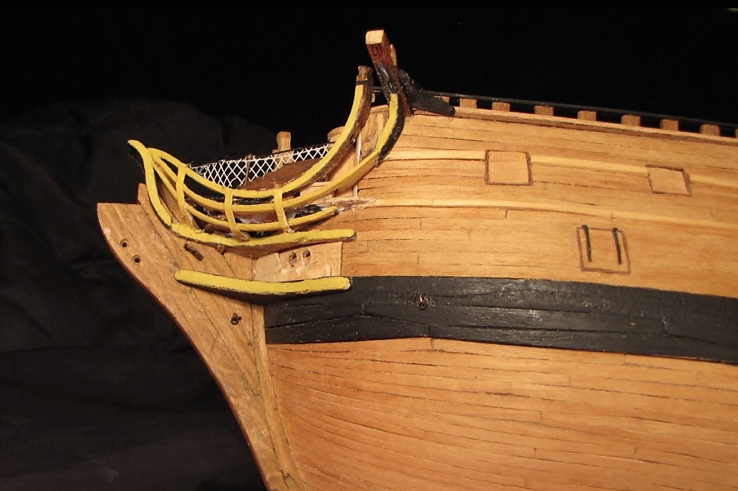
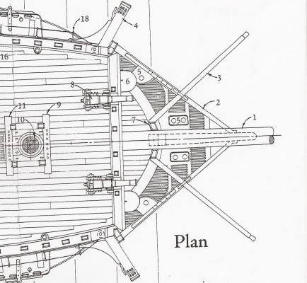
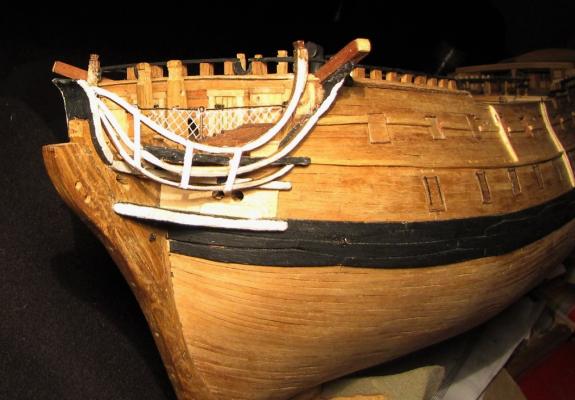
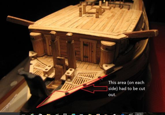
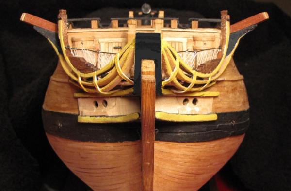
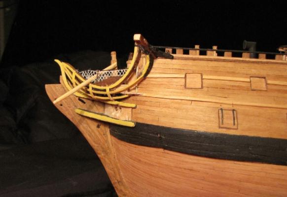
I feel I've reached a milestone in the build --- not that this should be a milestone, but it certainly is for me as I've been wrestling with this for about a month. After several attempts I've finally got headrails and timbers that are more or less "acceptable". I'm having to accept that this is about as good as I'm going to be able to achieve. Part of the problem was the way that I had constructed and fitted the heads platforms. In the plans and drawings there was only one illustration of these platforms . . . and I had made them just as I saw them in the plan. Here is the plan >>> These platforms looked OK when I fitted them but after I tried to create reasonable rails around them I found it just wasn't working for me. The top rail wasn't much of a problem but I just couldn't get the middle and lower rails to fit and look anything like they were supposed to look. Despite having made the platforms according to the plan, they were preventing correct (or even near correct) fitting of the middle and lower rails. I 'chopped' the front part off the platforms and made a further attempt and the pretty awful result can be seen in the following photo. (Yes - this is quite awful, but you should have seen the earlier attempts!) >>> I wasn't happy with this but out of frustration I painted the rails, timbers and cheeks an off-white colour ~ perhaps thinking that a coat of paint would somehow make them right --- it didn't work! . . . they were still awful! The photo shows that the lower curves of the middle and lower rails were actually below the upper cheek when they should have been above, and it was the platforms that were causing this problem, so more butchery was the only answer. Out came the hacking knife and a chunk of the platforms went in the bucket. The following photo shows how much had to be removed >>> Only after that demolition job was I able to get the rails looking nearer to acceptance >>> Not having the steadiest of hands isn’t the best for doing fine paintwork and the paintwork on the headworks needs to be sorted properly and that’s something I’ll address later. Right now I’m just pleased that I’ve eventually got the structure of the headworks as correct as I’m going to get it. I’m not convinced that I like that yellowish colour that I have used. I haven’t really given any thought to colours that should be used so please suggest what colour would look best on these headworks. Blue? – Gold? --- I don’t know ??? View from the side >>> . . . and with a boomkin in position >>> That boomkin was just being “road tested” to see how it would look, and along with its neighbour will be going back ‘in the box’ for now as they’re very vulnerable poking out there at the front of the ship. Due to having no experience I wasn't looking forward to this part of the build before I arrived at it, and I have to say that, for the most part, I didn't enjoy all the frustration (and feelings of wanting to throw the model out the window!) associated with it . . . but it's done now and the exercise has hopefully added to my experience.

-
Well ~ all the best descriptive words have already been said here so many times, so I'm just going to say:- 'Anything this good should be illegal !!!' . . . and I also have to say: WOW !!!
- 1,215 replies
-
- 5
-
-
- sloop
- kingfisher
- (and 1 more)
-
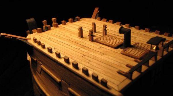
. December has come and gone and another year has begun, and the last month has been very frustrating in the shipyard. I ended my last posting with the words:- "but I'm not sure the head timbers will be straightforward" ~ well, I'm now sure that the head timbers aren't straightforward !!! Over the last few weeks I've spent considerable time making and fitting head timbers --- and removing, and re-making and re-fitting and removing them several times and right now at this time I still don't have an acceptable result. It's getting closer to being something acceptable, but it's not there yet . . . So there won't be any photos of the ship's bow in this posting. Just to get away from the frustration of the headworks I've spent some time adding some fittings to the quarterdeck. A kevel, a staghorn and a shot garland were added to each side of the deck, and almost immediately I was a little less than happy with the colour of the kevels and staghorns. They were just not right -- they were a bit too white in contrast to the surrounding timbers of the ship. I thought about removing and replacing them but was reluctant to do any more butchering after all the butchering I had been doing at the beakhead. Here's a pic of the offending "white parts" >>> Using wood stain to colour the parts seemed like an option but I was a bit concerned that I might stain the deck planking, since I don't have the steadiest hands! Anyhow, I decided to mask the surrounding areas and delicately applied the stain and saved myself the operation of removing and replacing them. Here's how they looked after staining >>> That photo above also shows the main bitts with the rail and pins, as well as a pinrail and pins fitted to each side of the deck . . . and they were a further source of annoyance to me! As I had previously had considerable failure in my attempts to turn some spindles down to just over 1mm diameter I decided I would buy 'over-the-counter belaying pins. I bought 8mm pins as that length was just about right for the scale I'm working at. However the diameter of over 2mm was just far too 'fat' for scale. I was reluctant to try to thin them down because of my previous experience so I fitted them as they came . . . but each time I looked at them on the ship I just hated them. Out came the pinrails and I was surprised that I was able to push the pins cleanly out of the rails, despite them having been glued in. I was able to turn them down to around 1.2 - 1.3mm -- any thinner than that and they were breaking. At that size they are still over scale but they look better than their original thickness and I'm just going to have to live with them. They would have to be around 0.5mm diameter to be properly in scale and I'm just not capable of that. Here are the belaying pins after refitting >>> OK ~ I'm heading back to that beakhead now . . .


- 257 replies
-
- 10
-
-
ancre Le Fleuron 1729 by rekon54 - 1:24
Bluto 1790 replied to rekon54's topic in - Build logs for subjects built 1501 - 1750
When I look at all these photos I can't believe I'm looking at a model --- IT MUST BE A REAL SHIP !!! -
Hi Nils, After 63 pages of this build log I feel that I should apologise that I haven't caught up with your superb model previously! There are so many great build logs here on the forum and I just can't get to them all! Brilliant build!
-
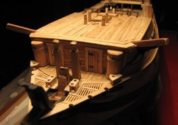
Staying on the foredeck, the timberhead 'bases' for the rails have been fitted along with the 2 gun 'ports' for the bow chasers. > . . . then the rails were added > The forward corners where the fife rail meets the side rails are presently just 'hanging ' there without support. The plan is for support to come along in the form of the head timbers which are an "in the very near future" project ~ as soon as I can figure out how to make these fancy, curly things, and fit them! Some of you may have noticed from a couple of the pics above that the head platforms are already fitted to the ship. (Yeah, go back and have another look!) These were fitted prior to the foredeck rails making an appearance > These were fairly straightforward, if fiddly and time consuming, to make, but I'm not sure the head timbers will be straightforward. (At least the sailors now have toilets to go to!)

- 257 replies
-
- 10
-
-
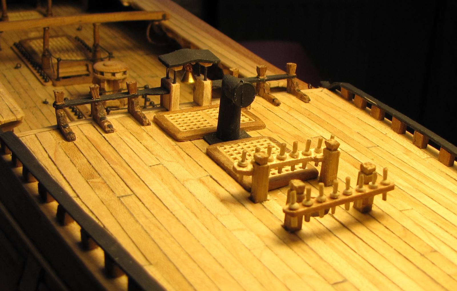
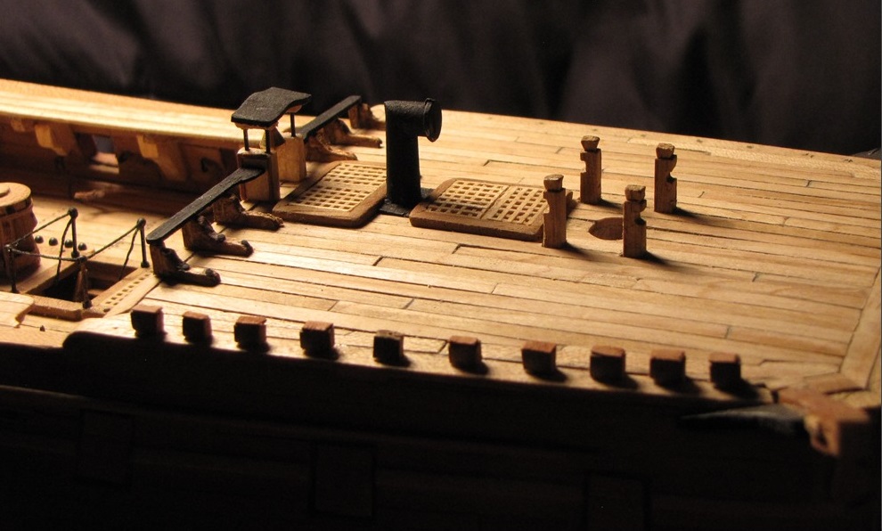
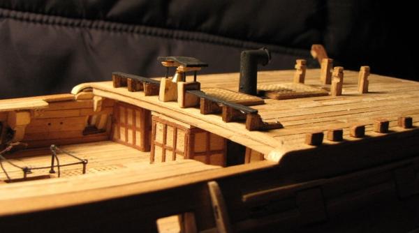
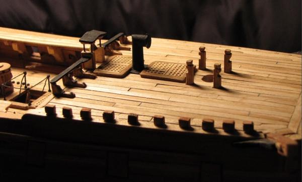
Thanks for your comment, Hans, and to the others for the 'likes'. The belfry now has its bell and it looks like cooking facilities have been installed as there is now a chimney sticking up through the deck of the forecastle. (but there isn't really any stove down below. ) The fo'c'sle rail still awaits the cappings to finish it off, but they're real tiny parts to make and very fiddly to fit so they'll be coming along at a later date. (I hope?!) A start has been made along the starboard side to prepare for the side rail but the port side rail, the fiferail and this starboard rail effectively form a continuous rail so I'll have to spend some time fitting the 'timberheads' for these as well.
-
Hi Piet, As for the rigging of the guns on the upper deck (of my ship) I've "copped out" somewhat and opted for a much simplified installation for 2 reasons:- 1) Unlike your ship, the guns in the waist of mine aren't 'open' as there are the gangboards above them and the guns will therefore be partially covered and obscured from view; and . . . 2) because of the gangboards I could foresee that it was going to be a very tricky (if not near impossible) task for me to rig the guns as they really should be. You'll see from the photo below that although my guns aren't in position yet, a very rudimentary 'system' of rigging has already been put in place. In fact these ropes have been there since even before I carried out the secondary planking of the hull and also before the gangboards were in place. Before I did the final hull planking I planked the inside of the bulwarks in the area of the waist so that I could drill and fit the rings to which I attached these crude rigging ropes. So, when I look at your rigging I am definitely very impressed !!!
-
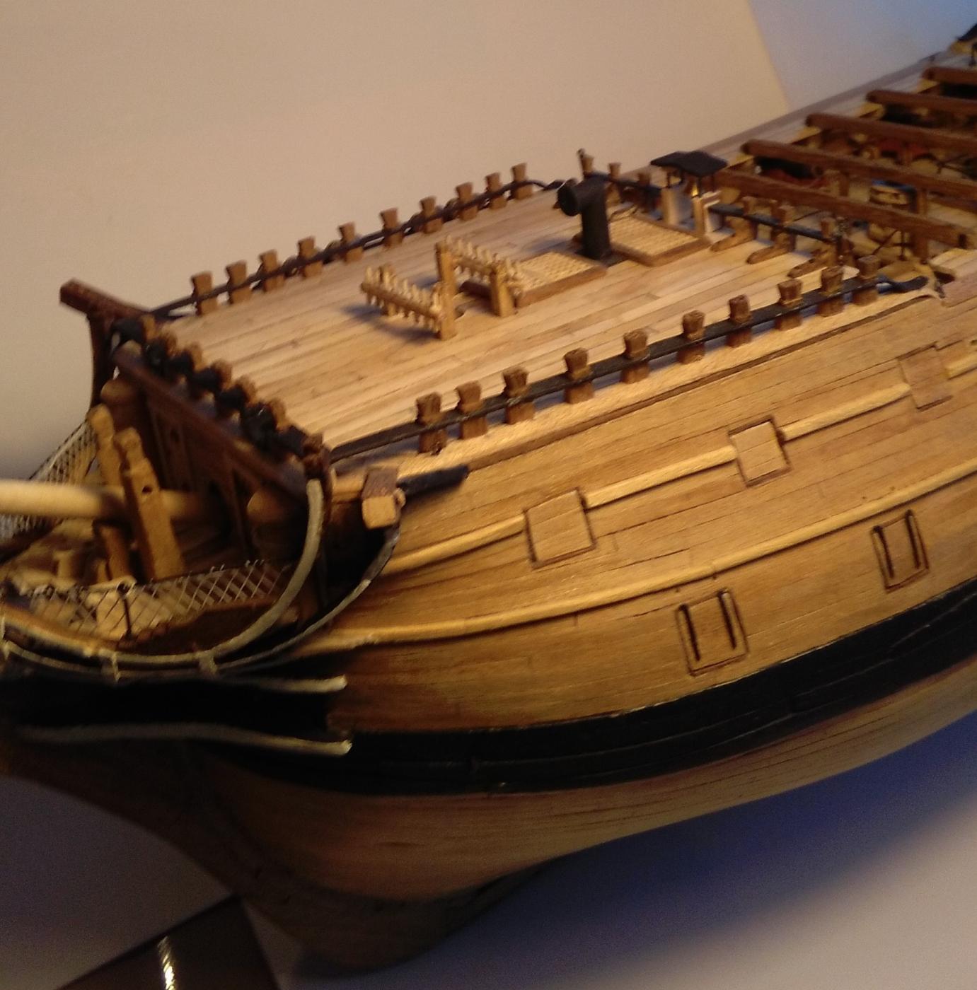
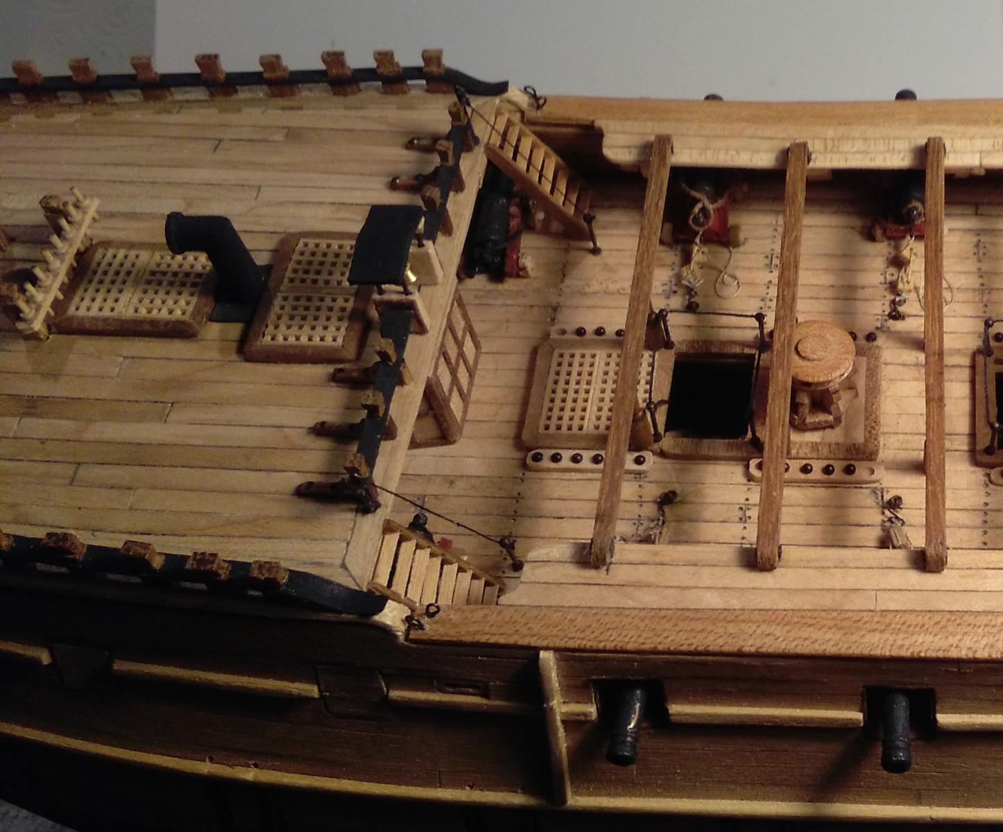
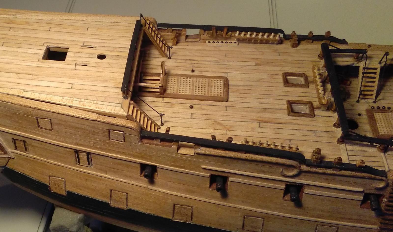
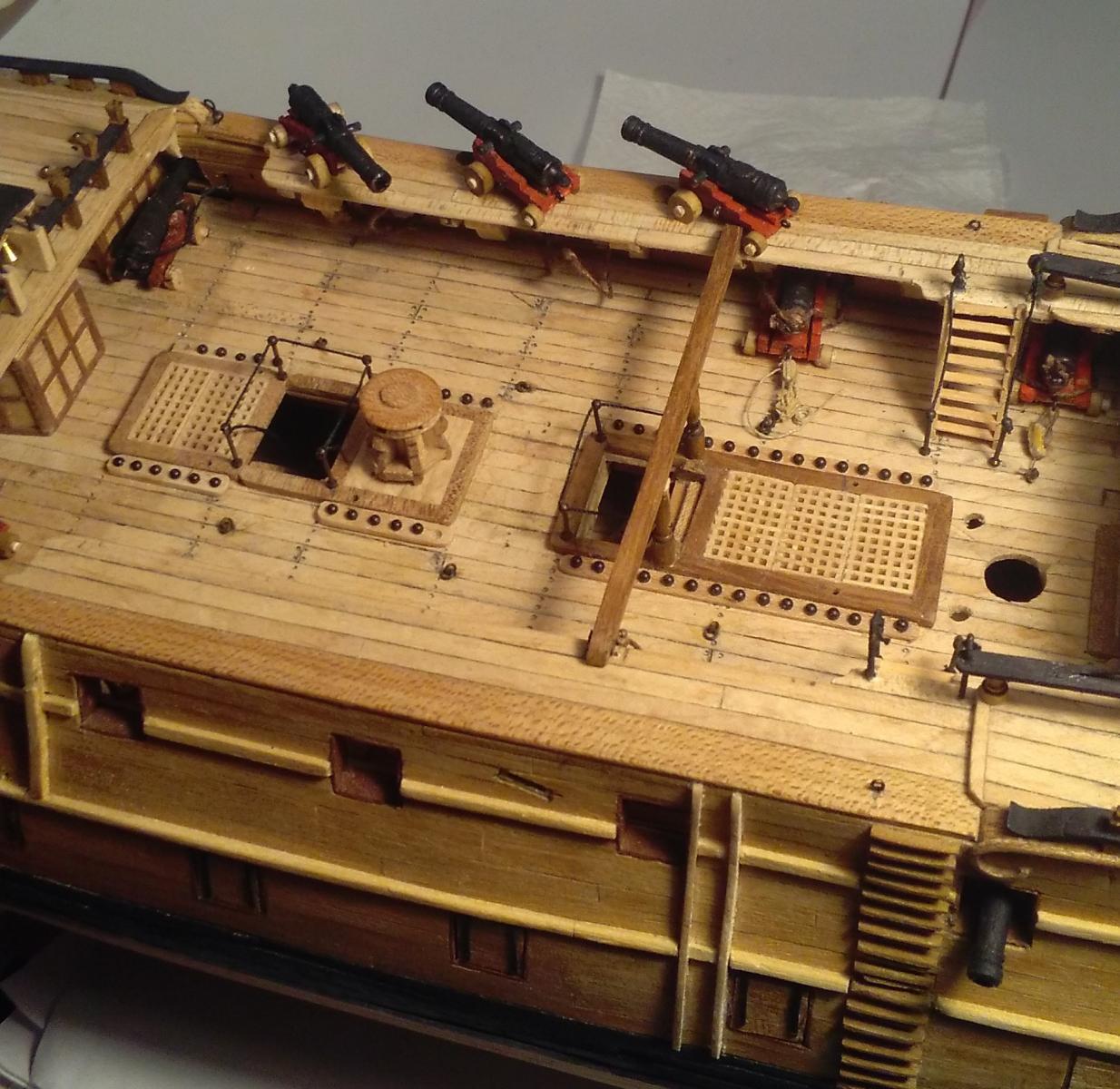
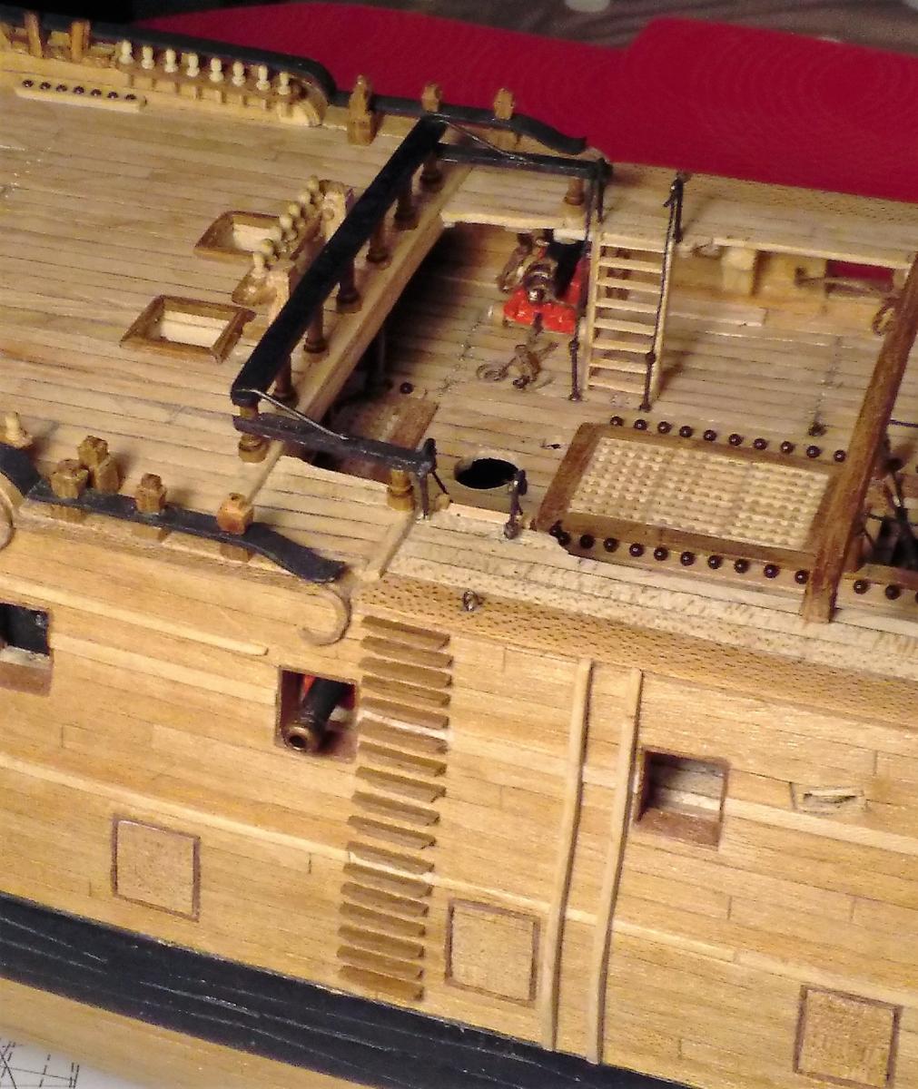
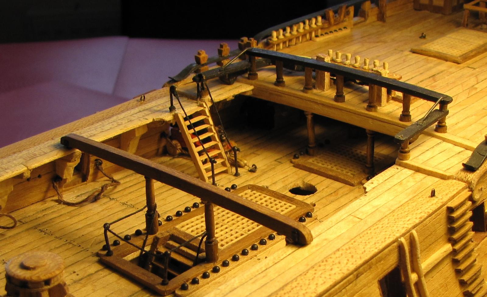
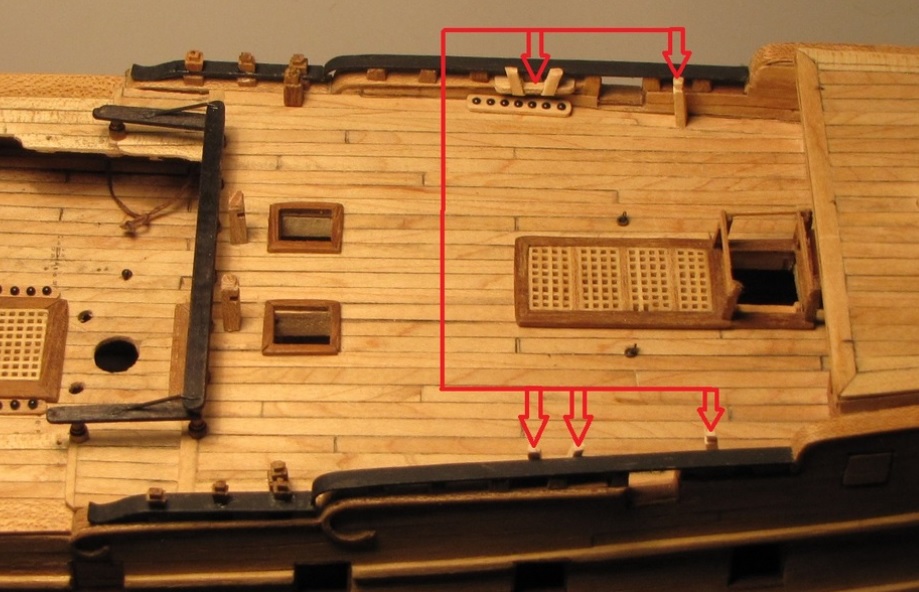
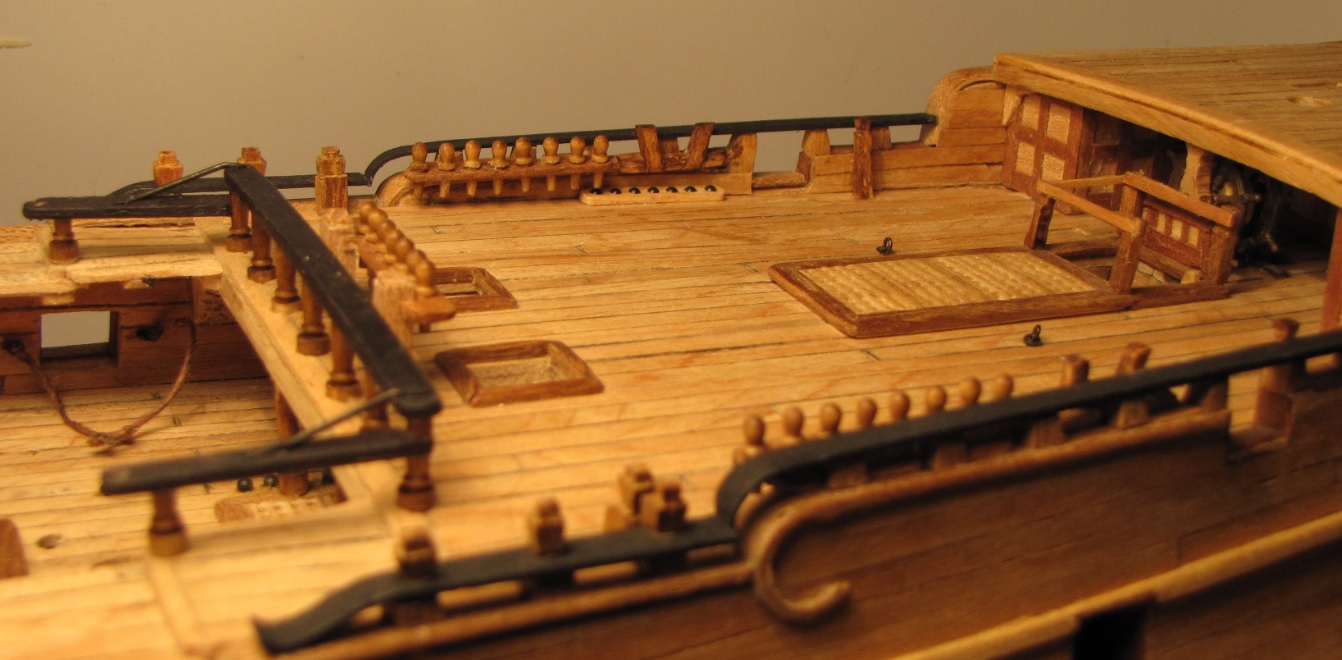
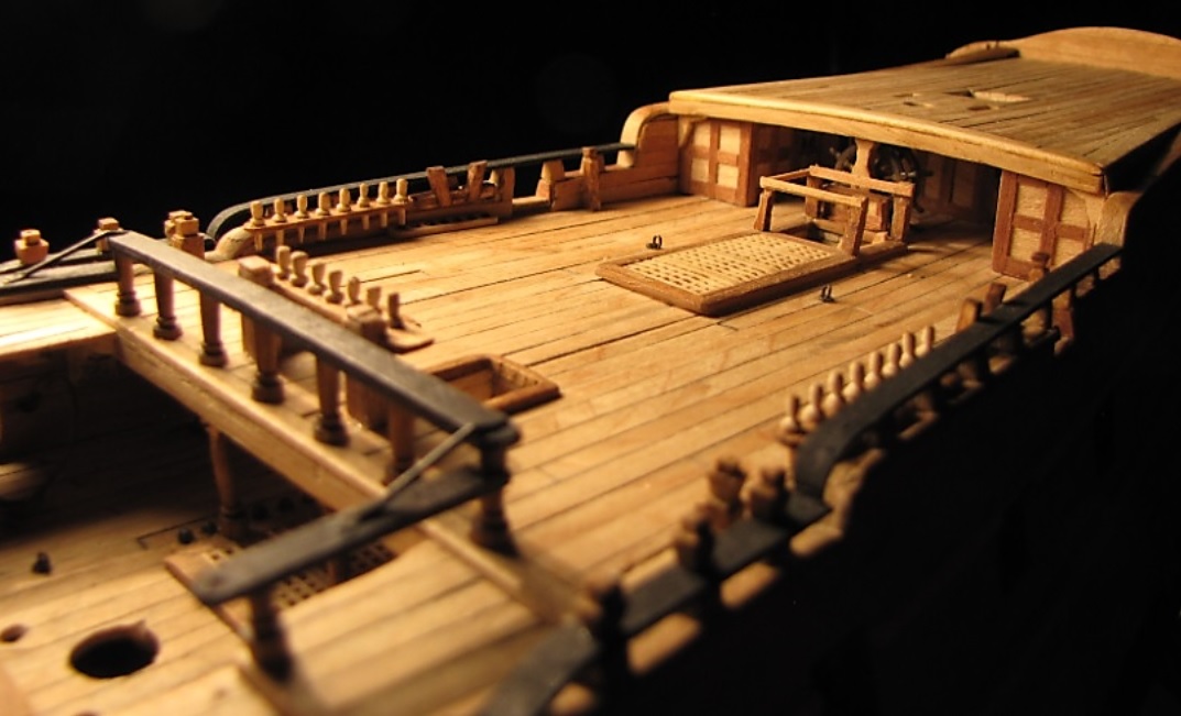
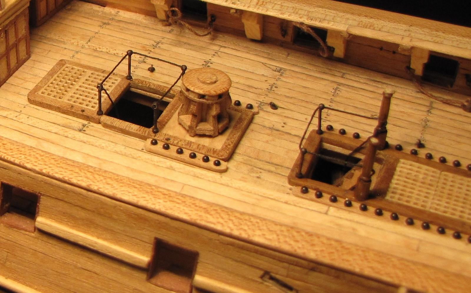
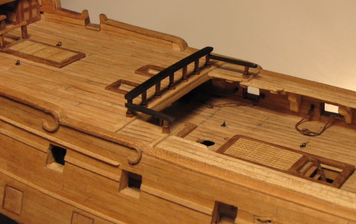
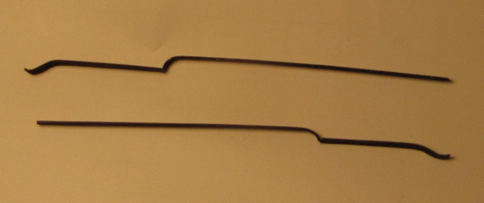
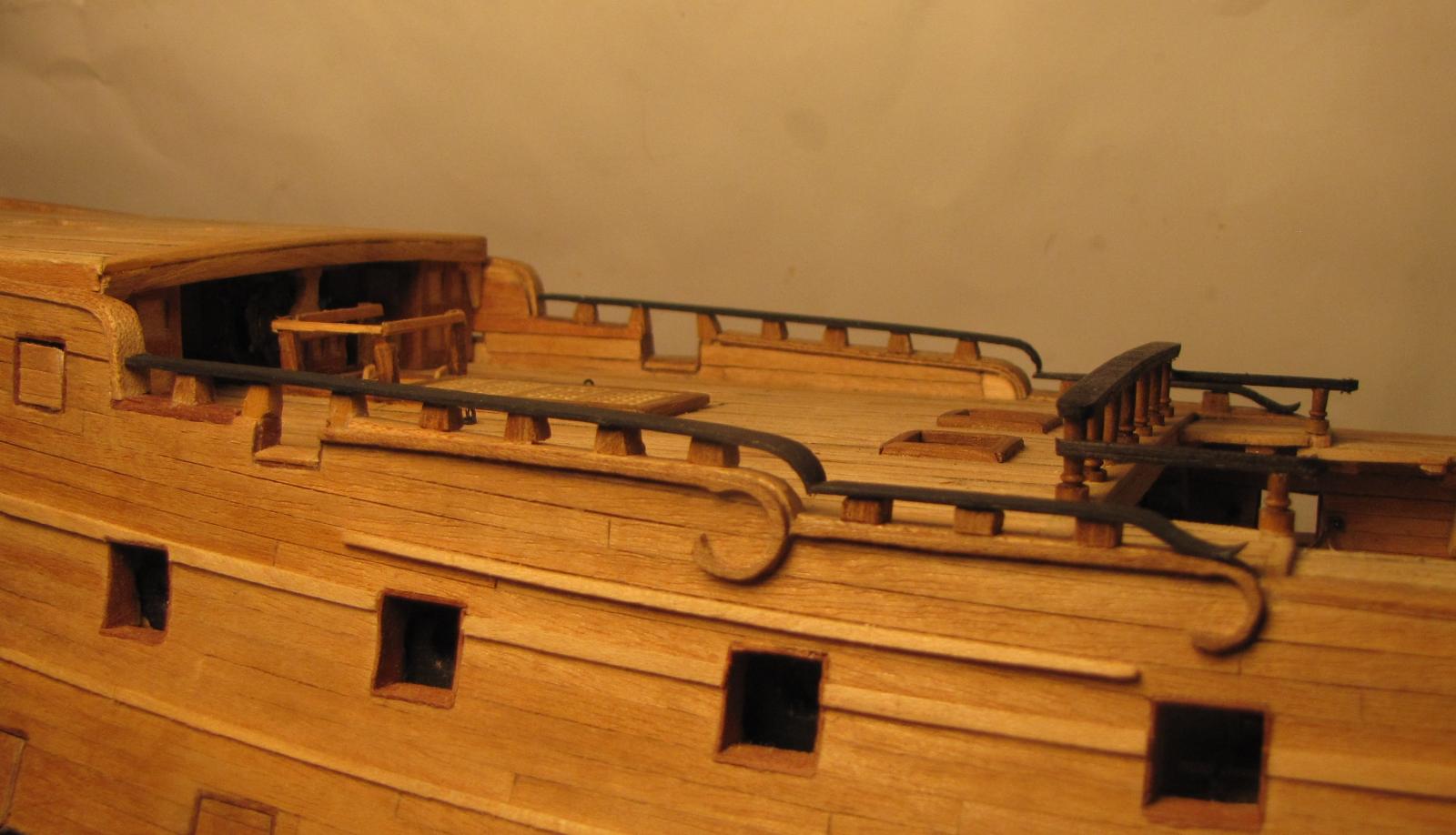
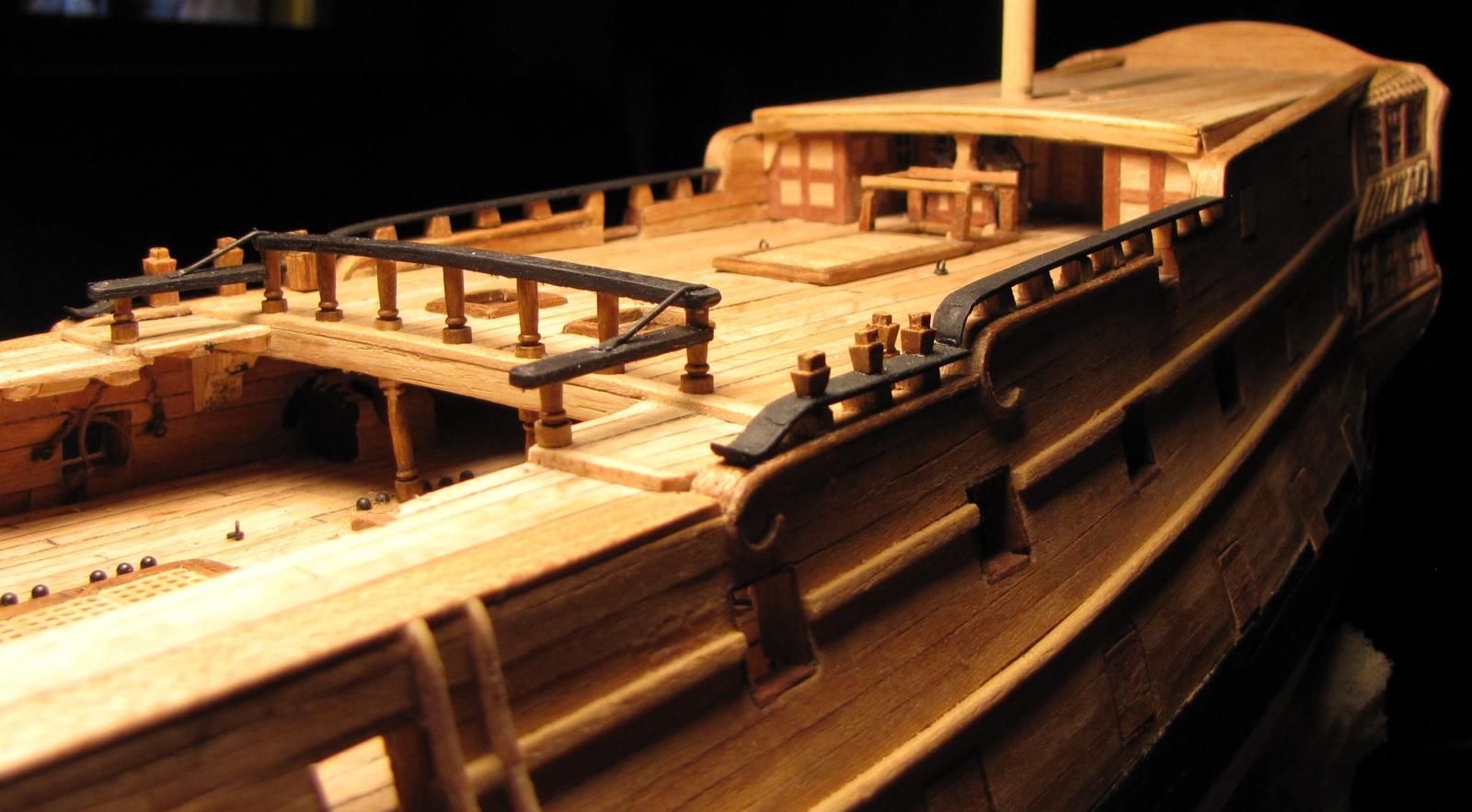
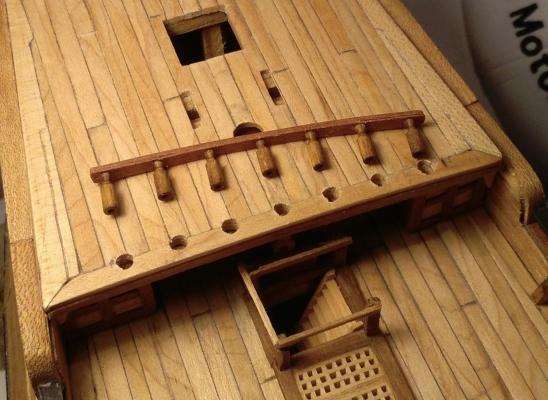
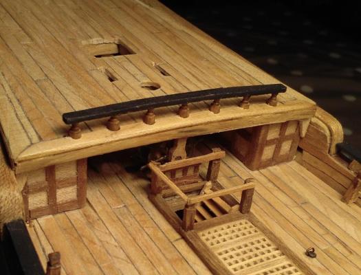
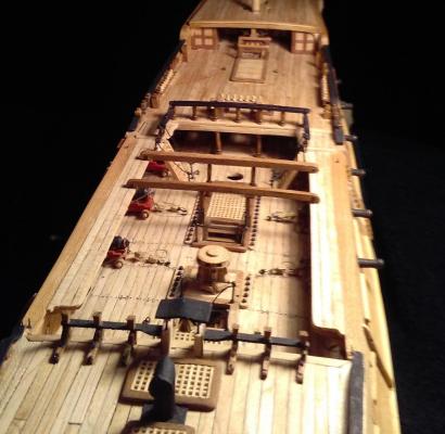
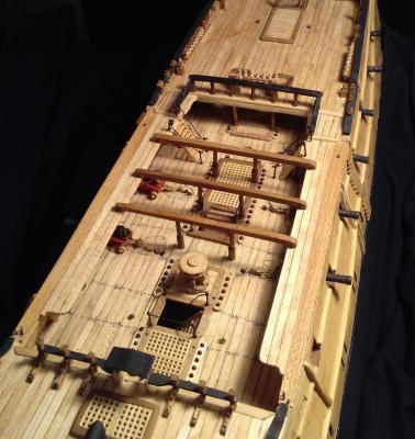
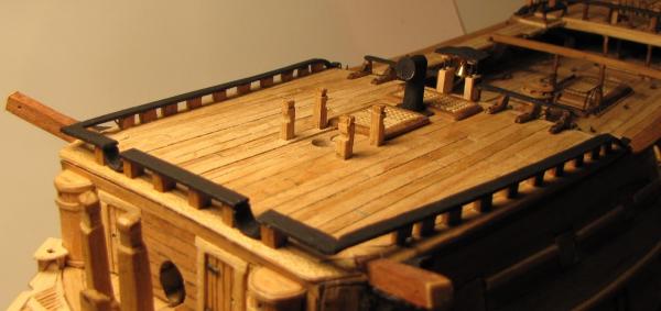
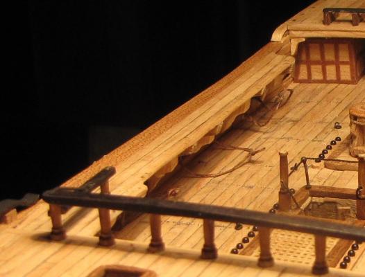
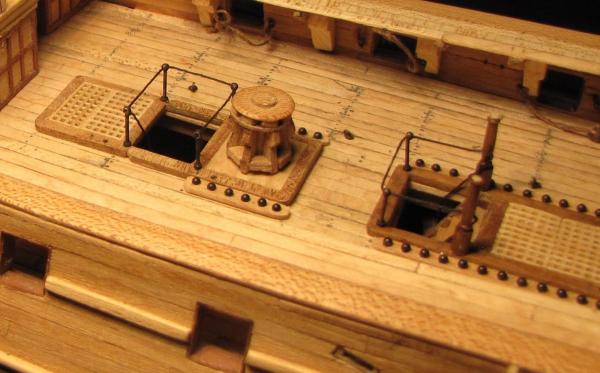
Still a few things to be done around the quarterdeck which I'll get back to later. In the waist of the ship there are several things that need done. Most of the shot garlands have been fitted but there are still a couple missing. Four ladders serve this area (2 to the Q/deck & 2 to the fo'c'sle) and 2 of them have been made some time ago and are waiting 'in the box'. I don't want to fit the ladders or the skid beams (which are also already prepared and waiting . . . ) as I don't want to make the installing of the guns any more difficult than it has to be. I've already done a trial 'dry run' of trying to get a gun & carriage in position with the beams and ladders in position and I didn't like the experience. I know I could fit all the guns first but I'm a bit reluctant to do so as they will be something else sticking out the side of the hull that I would have to try to avoid damaging. I have fitted the guard wires/ropes around the 2 companionways on that deck. When doing so I found that 2 of the skid beam supporting columns would have been very close to being in the same position as 2 of the guard rail stanchions --- so, I employed these 2 columns in the dual role of stanchion and column > . . . and seein' as these 2 columns were sticking up looking very vulnerable, I decided to fit their skid beam hoping to stabilise the columns and make them less likely to be damaged. That single skid beam won't hamper any later efforts to fit the guns. > While I think about the order in which I will finish the 'works' in the waist, I moved forward and began doing some 'stuff' up on the forecastle. I made a start on the fo'c'sle rail which still waits to be 'topped' off and the basic structure of the belfry awaits its canopy and bell. >

- 257 replies
-
- 12
-
-
Hi Piet, I'm just catching up with your build log here. I'm also trying a build at the same scale as yours, but at 1:80 I'm finding it difficult to re-create many of the small items with any amount of reasonable accuracy. (Maybe if I had started about 50 years earlier I might have been a bit better! ) I'm very impressed with what I've seen here on your log!
-
I think someone needs to write a book entitled "Superlatives R Us" so that I could refer to it and find some words that haven't already been said here . . . but for now I'll just have to say ~ WOW! . . . Fantastic!
-
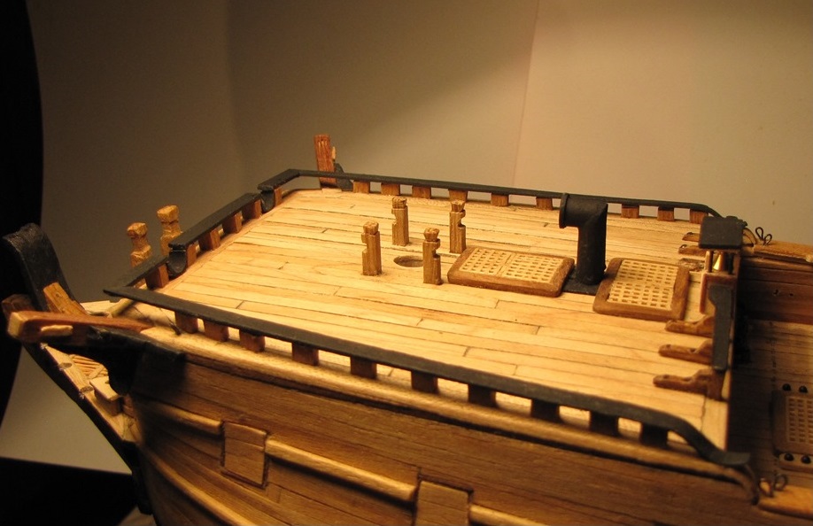
Now that the decks had all been planked some fittings got under way. The parts of the quarterdeck rail had been tucked away in a box for a couple of years so it was time for them all to come together > Cap rails for P & Stbd bulwarks > 'Pseudo' timberheads awaiting the cap rails > Cap rails fitted > 6 'cappings' (not sure of the proper name) for the timberheads are required - 3 for each side at the fore end of Q/deck at the step-down to the gangboards. Here are 3 of the 6 > Also 2 'stand-alone' timberheads - one at each side. Here's one of them > . . . and here they are fitted >


- 257 replies
-
- 12
-
-
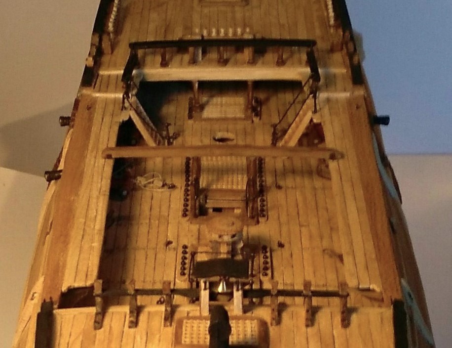
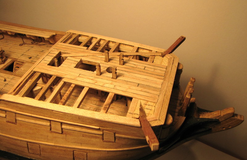
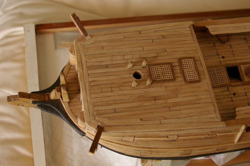
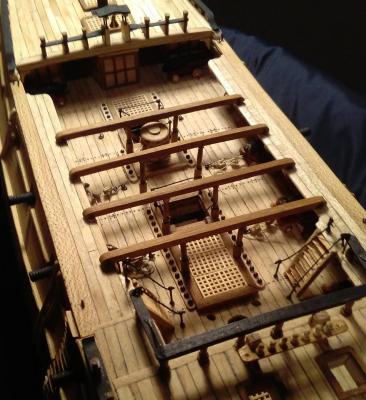
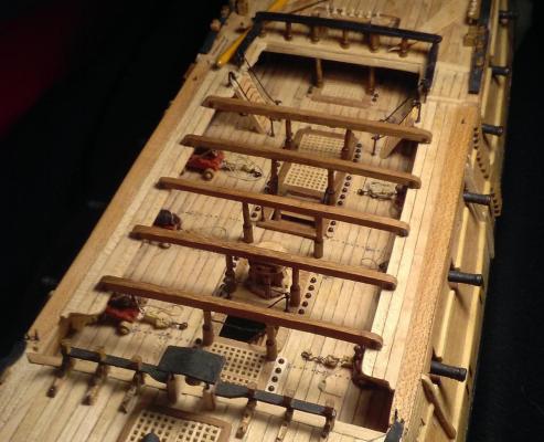
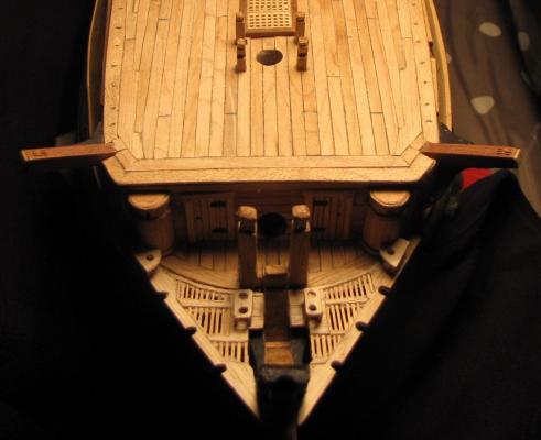
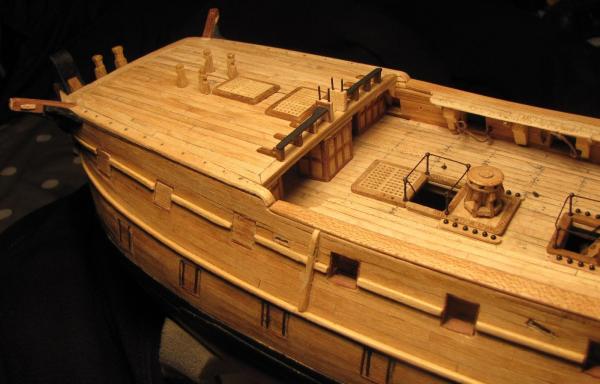
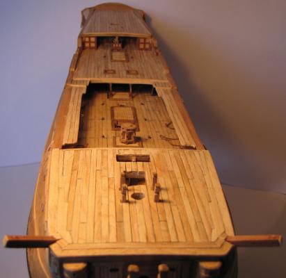
Well, this feels strange --- returning to this after more than 2 years since my last posting. Soon after that post, work on the ship ground to a halt while other 'life things' started to happen. I hadn't intended that no work would be done for almost 2 years but I eventually got back to it around August this year. Before work tailed off I had managed to get the deck planking completed, and here are a couple of pics from back then. Last part of planking gets under way on fo'c'sle > Planking now complete from stem to stern > Then the gratings were laid in place here > This was the last work done before Leopard collected some dust for a while . . .


- 257 replies
-
- 10
-
-
Help with Proxxon MF70
Bluto 1790 replied to Bluto 1790's topic in Modeling tools and Workshop Equipment
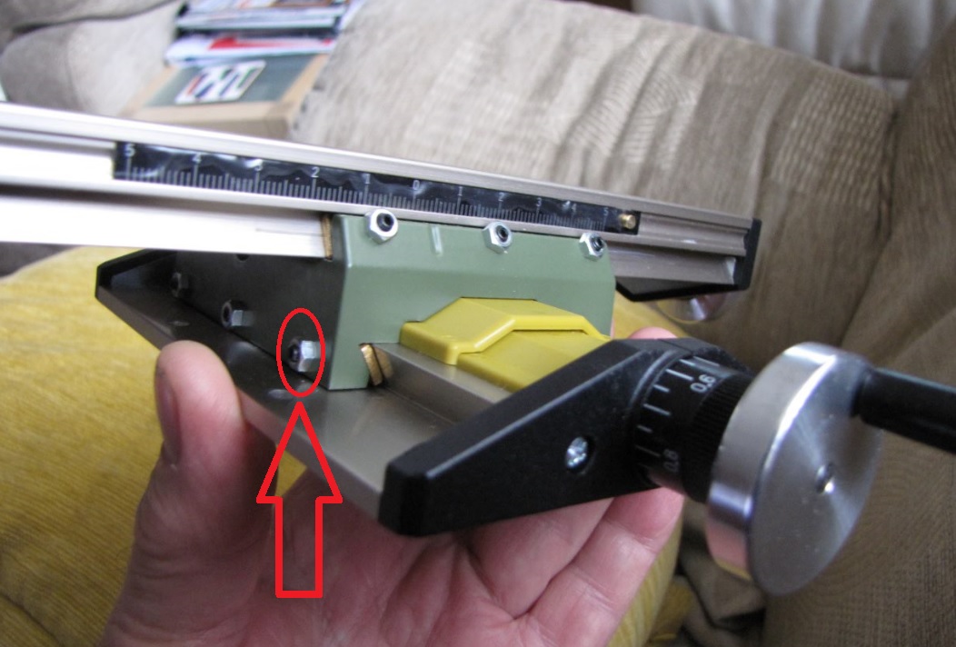
Earlier today I decided to make an attempt at Antony's suggestion. I slackened the locknut on the gib shown arrowed in the pic below, tightened the screw by hardly as much as half a turn . . . and the play was instantly gone. I quickly tightened the locknut before the 'lack of movement' changed its mind! The table is now rock solid instead of rockin' an' rollin'. Thanks Antony and everyone who contributed here. 
- 35 replies
-
- 10
-
-
Help with Proxxon MF70
Bluto 1790 replied to Bluto 1790's topic in Modeling tools and Workshop Equipment
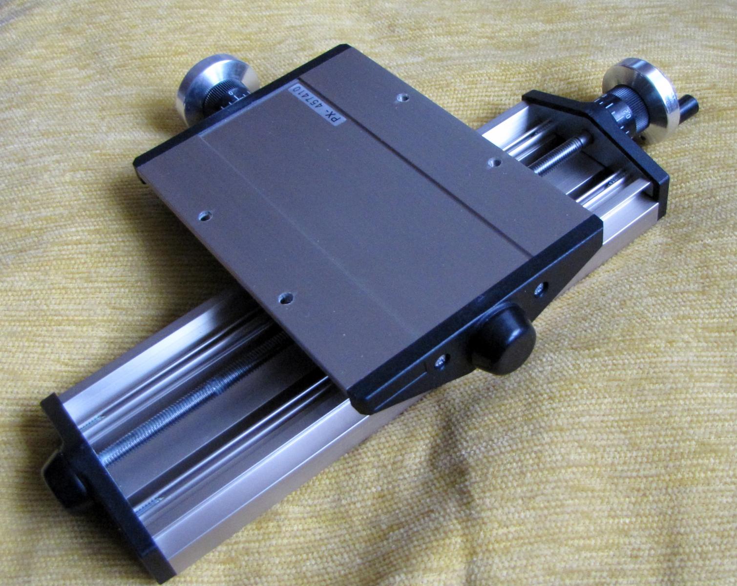
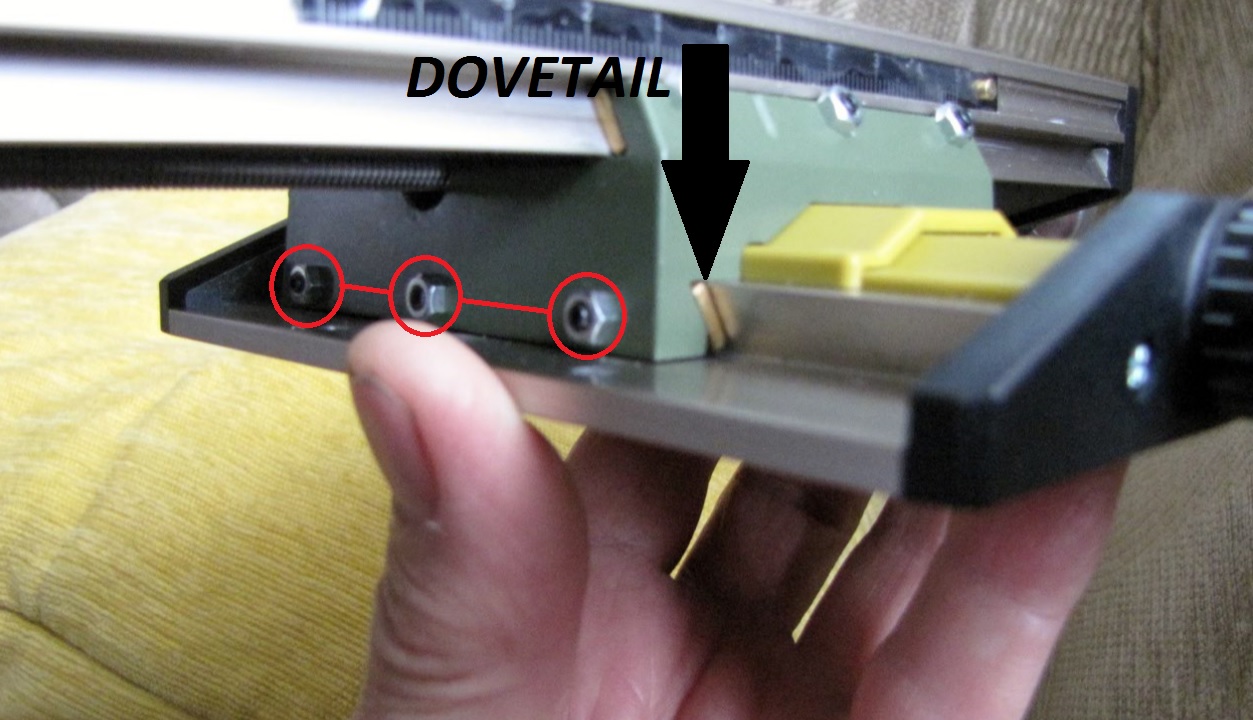
I removed the worktable and here is what is underneath > That base plate is a single piece aluminium extrusion and isn't attached to the green sub-base by any immovable fixings. (screws etc.) Now that I've given a little thought to it, it's clear that both parts CAN'T be permanently fixed to each other as the sub-base has to be able to travel in and out along the length of the base plate. I don't know about other milling machines, but this one uses sliding dovetails to achieve that necessary movement. In the following photo one side of that dovetail can be seen > As all of the unwanted movement (play) is occurring at each side of the dovetail I can only assume that the remedy must lie in eliminating excess 'space' at the dovetail. The only way that I can see how to do that is by using the 3 adjusters (gibs?) as shown circled in red in the above photo. (Are these the nuts and set screws that Anthony [above] refers to?) I may be wrong, but it seems to me that I would have to tighten each of these 'screws' until excess play was removed from that area, then re-tighten the locknuts. . . . and yes, I know that the sub-base would still have to have enough 'space' at the dovetail in order to be able to function as a sliding part. Of course, I could be completely wrong in thinking the above, but I can't see any other way of overcoming this problem ??? If anyone can suggest anything else -- please do! Thanks. 

-
Help with Proxxon MF70
Bluto 1790 replied to Bluto 1790's topic in Modeling tools and Workshop Equipment
On above advice I've emailed Proxxon along with a link to that video so that they can see the problem as well. . . . I feel that you may be on to something Druxey --- straight out of the box I just proceeded to attach the worktable as instructed. I really have no idea what lurks beneath the table as it didn't occur to me to check there for any kind of looseness. I'll check that out later tonight. I have to go out with the 'Boss' (wife) now!