yvesvidal
-
Posts
3,639 -
Joined
-
Last visited
Content Type
Profiles
Forums
Gallery
Events
Everything posted by yvesvidal
-
 Fantastic work Bryan. That model looks so much like the old fishing vessel, I used to see when I was a kid in France. Yves
- 45 replies
-
- 2
-

-

-
- Fischkutter
- Laser Creation World
- (and 1 more)
-
Absolutely amazing, I am in awe!! For having built the same model in 1/48th scale, I have to admire and respect the precision, and cleanliness of your construction, Mark. You are a true artist. Yves
-
Really tempted to get that kit. It would fit well next to my CAF Bellona.... Arghh... not enough time !!! Yves
-
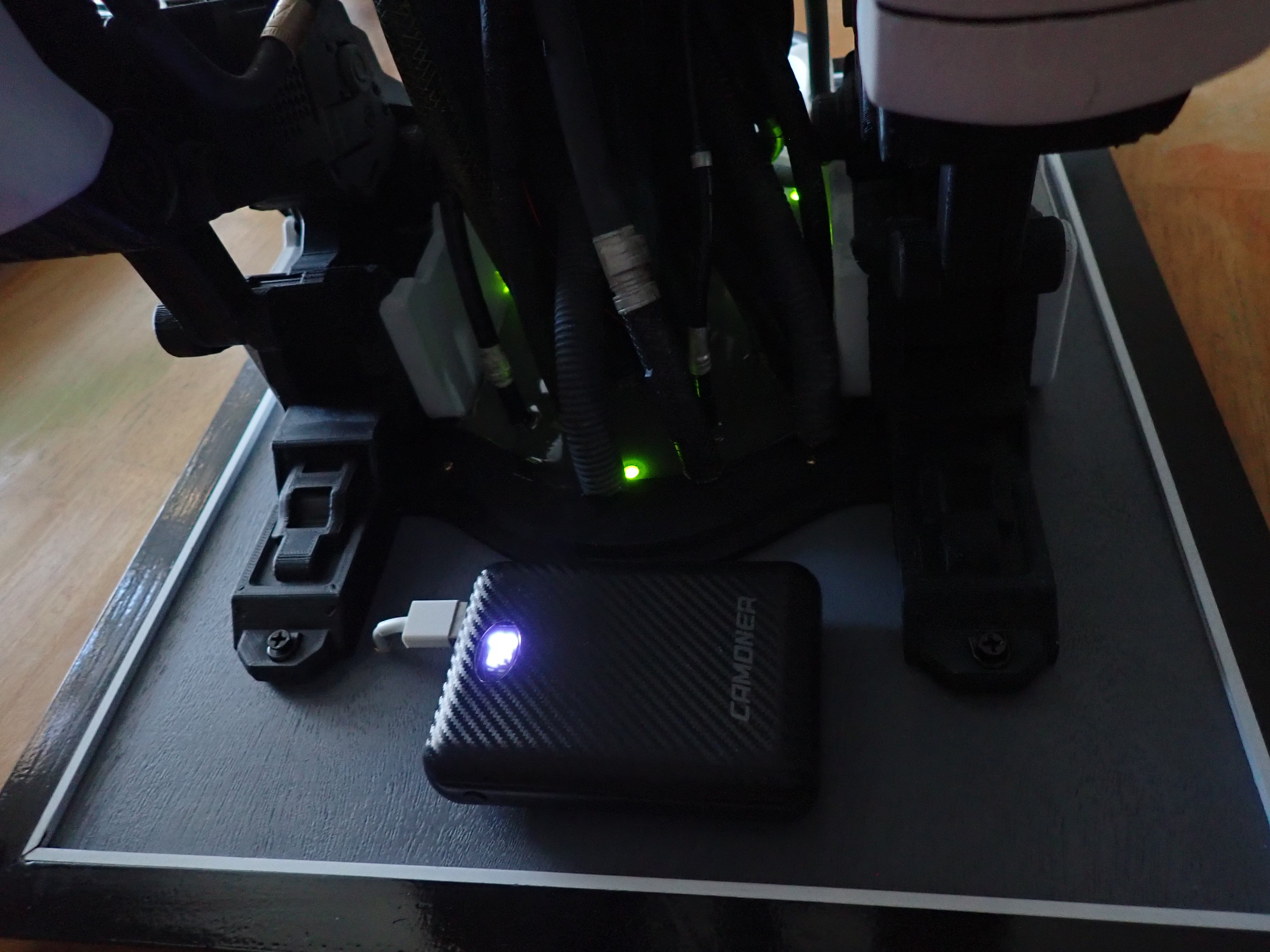
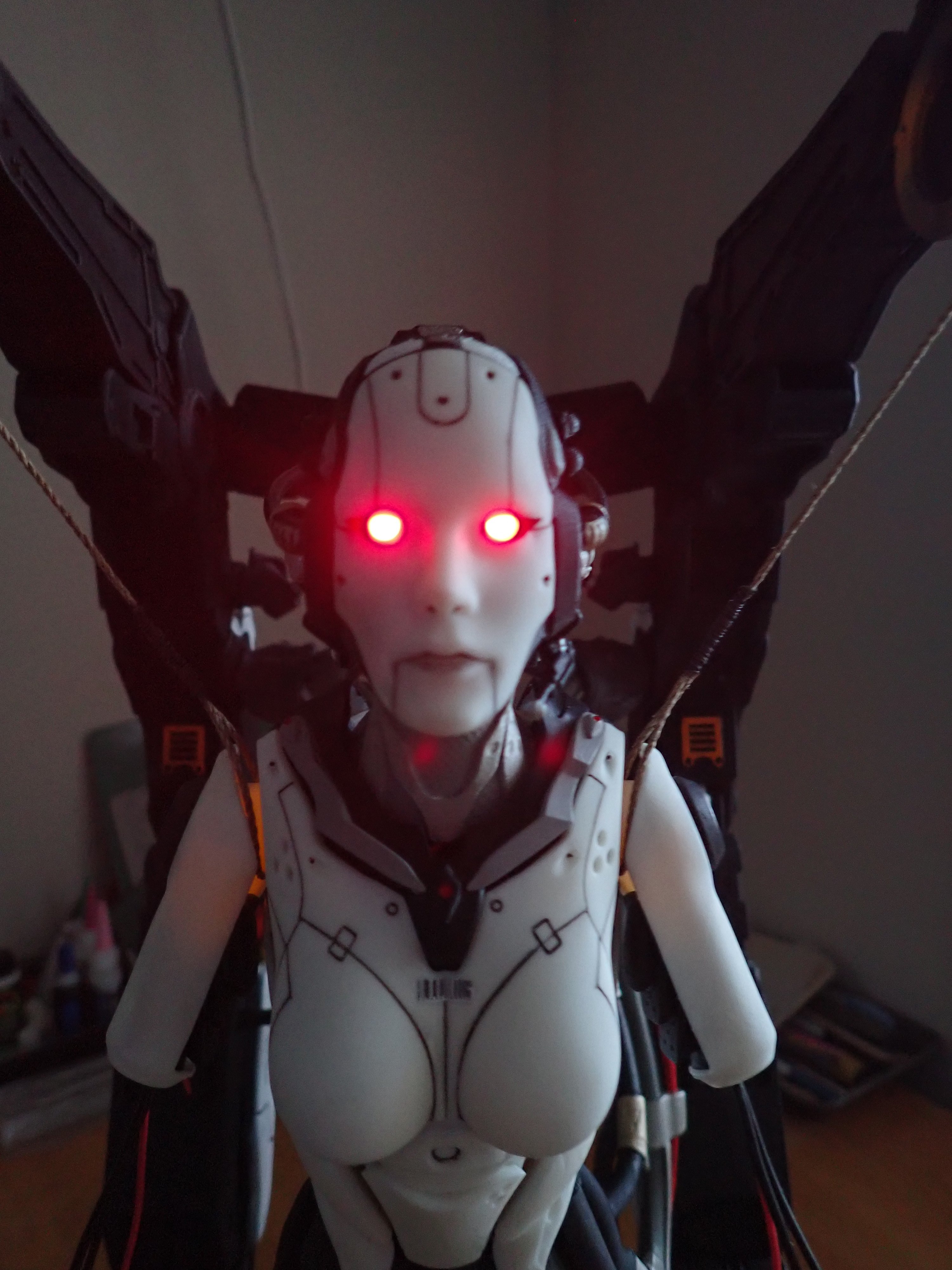
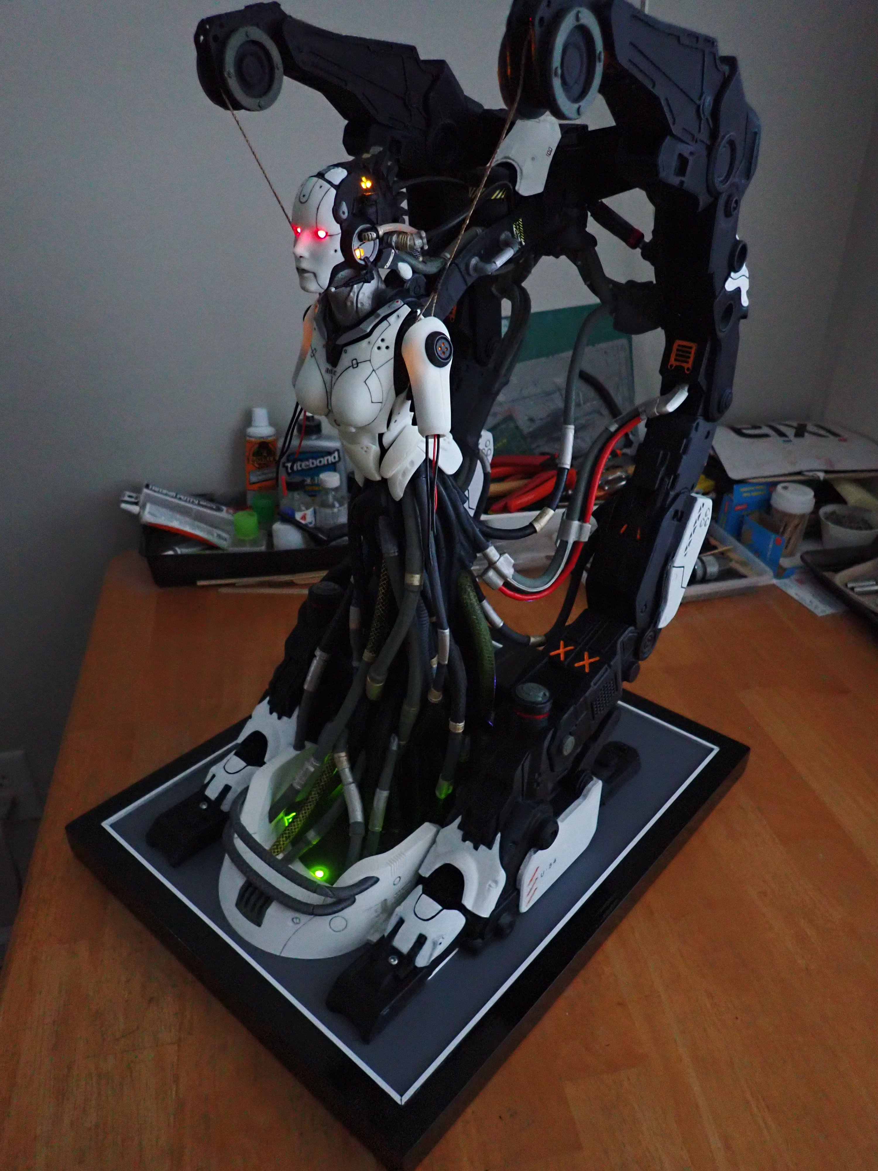
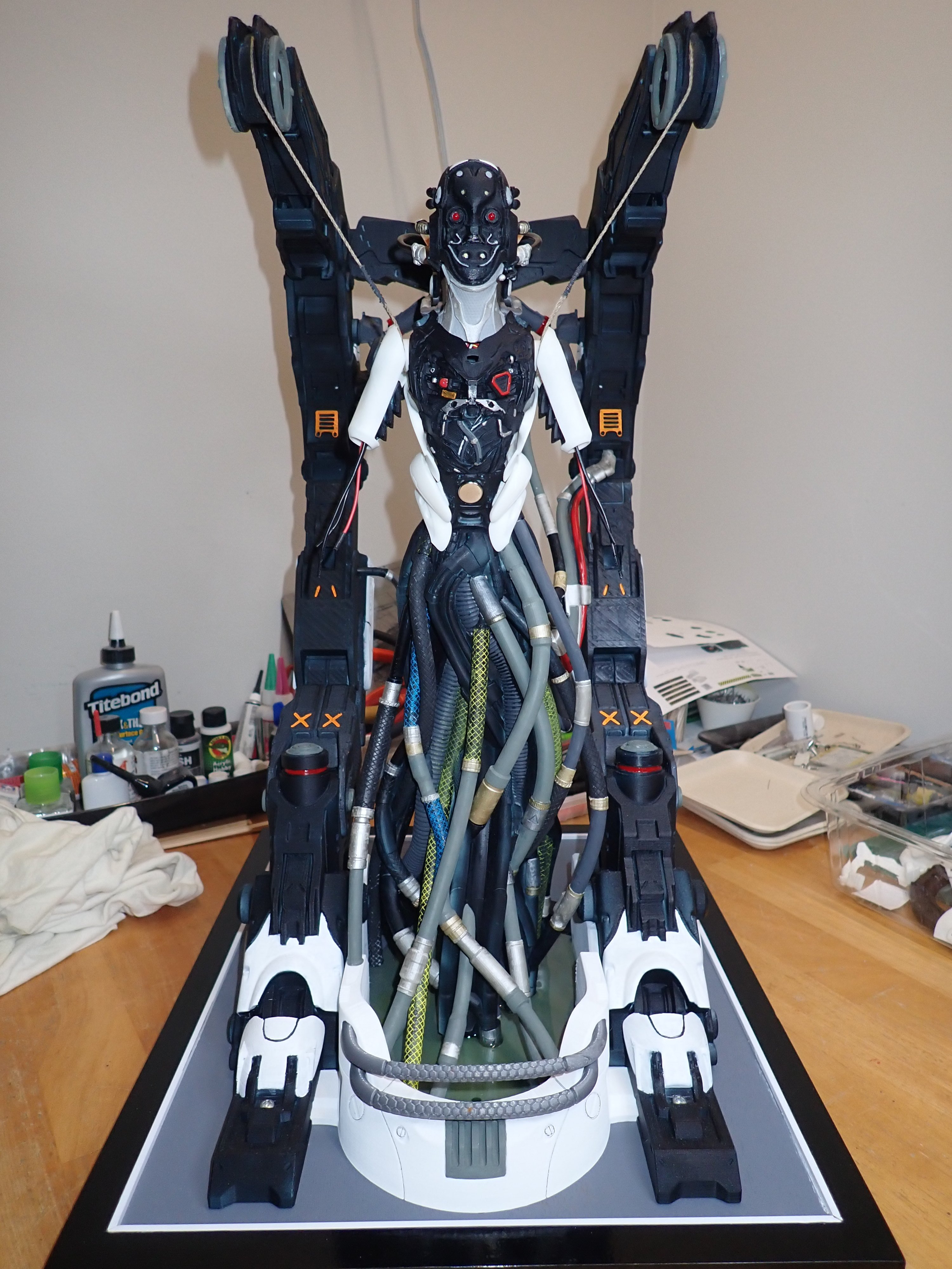
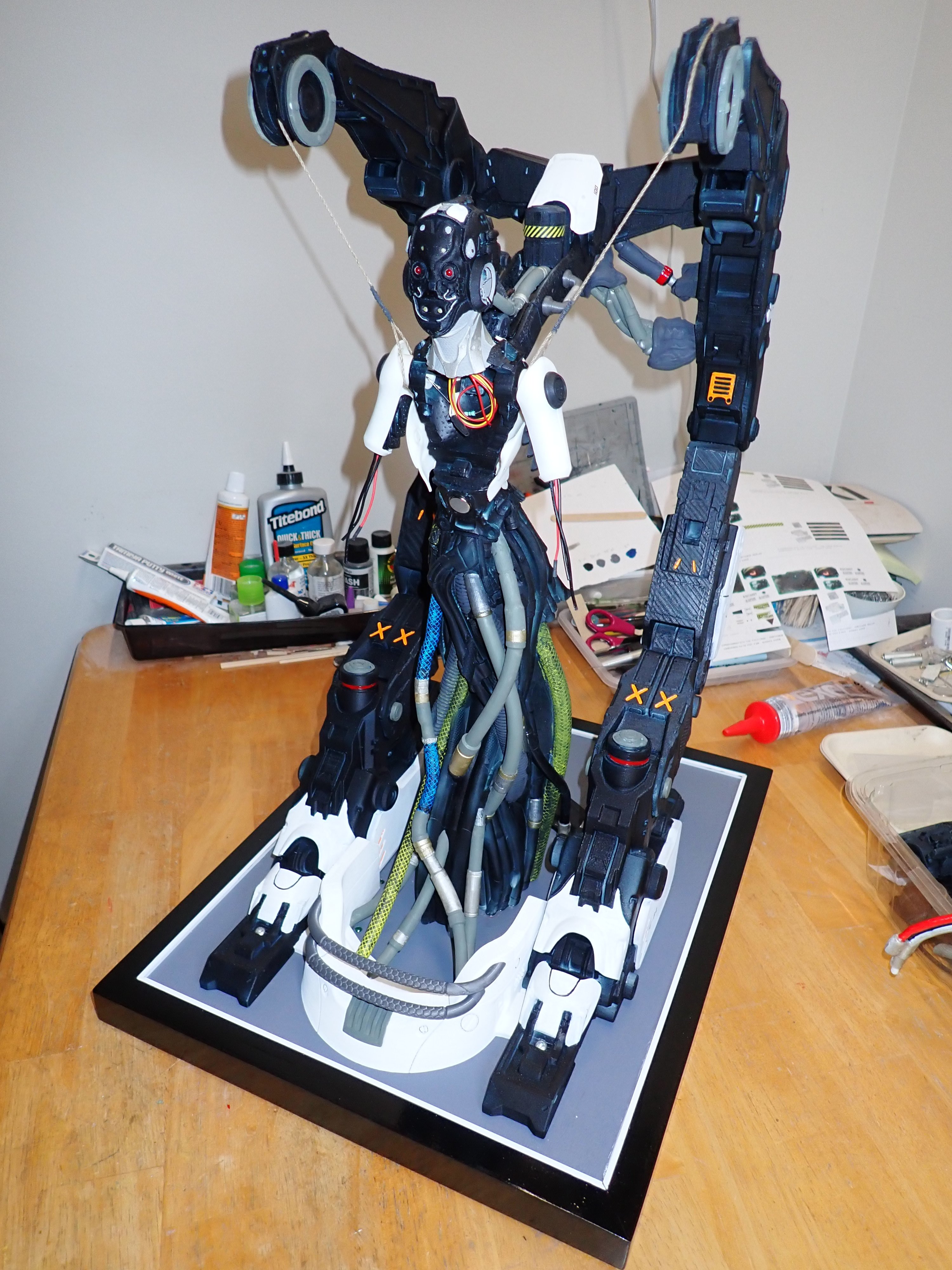
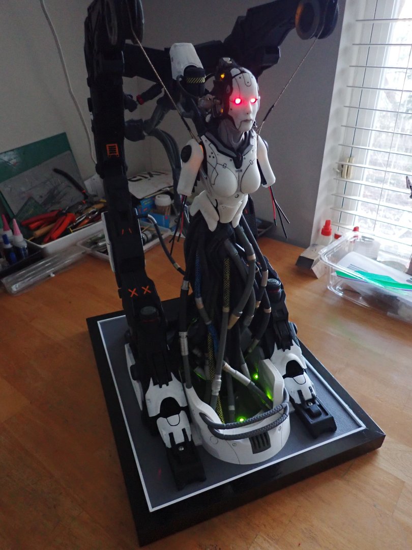
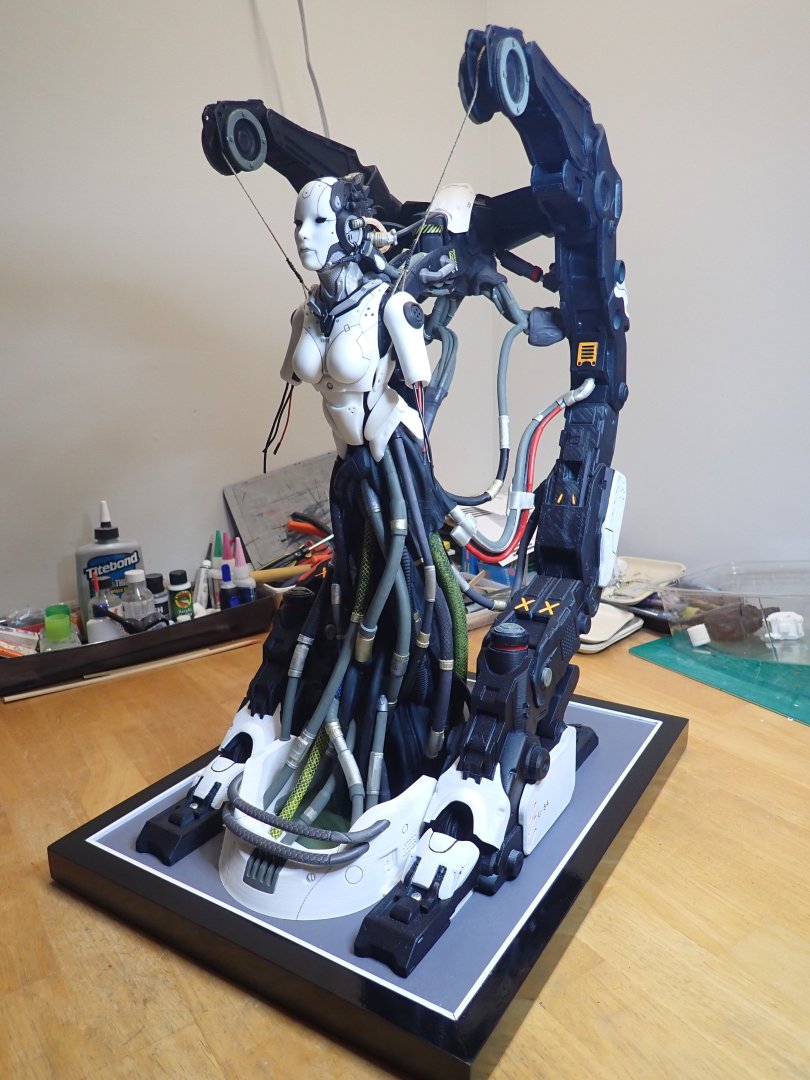
We are coming to the end of this build. It has been a steep learning curve overall, with filament printing (that I know a little bit better) and the new Resin printing process and equipment needed to fabricate all the parts. I don't regret investing in a resin printer and cleaning station as it opens many doors for beautiful rendering of figures and detailed parts for ship modeling. That AI creature had been taunting me for years, and I am glad that I was able to build it to completion. It will definitely be a piece for discussion.... I installed a power pack (5 Volts / 3 Amps) normally used for thermal clothes. A full charge can power the unit for more than a day. The murkiness of the cable pool.... Despite painting the back of the face mask in black, there are still some light leaks. A second coat will be required... And the eyes are reflecting on the base of the nose. That's it. Final step will be the computer interface to dialog with the AI creature. I hope you are and have enjoyed that project. Yves


-
I agree. This ship has always tempted me, but 1/35th is definitely calling for a monster, especially in height. I wish they would offer that model in 1/48th scale..... Yves
-
This feature is a sweeper that removes all ice, snow, rain and allows you to have a clear vision in front of you. Yves
-
For those of you who would like to see the AI Adjutant creature in action, youtube has a couple of videos: Yves
-
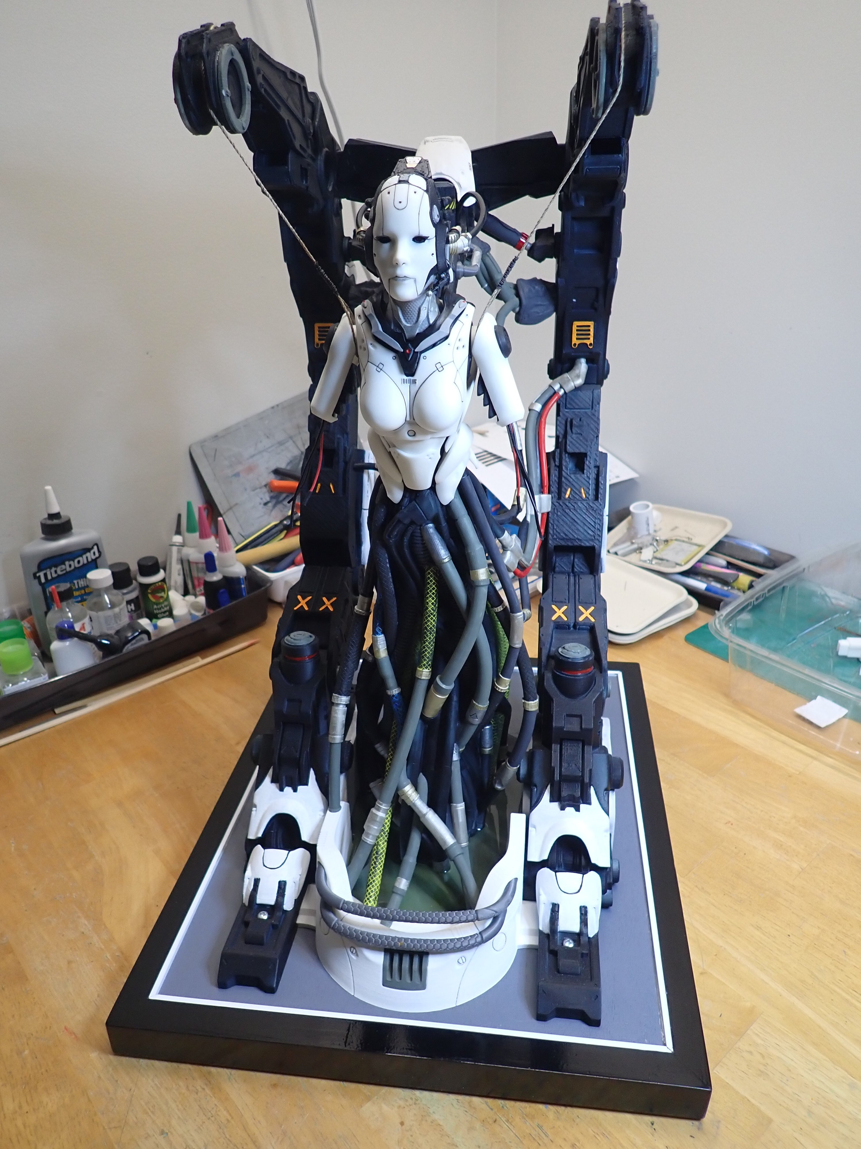
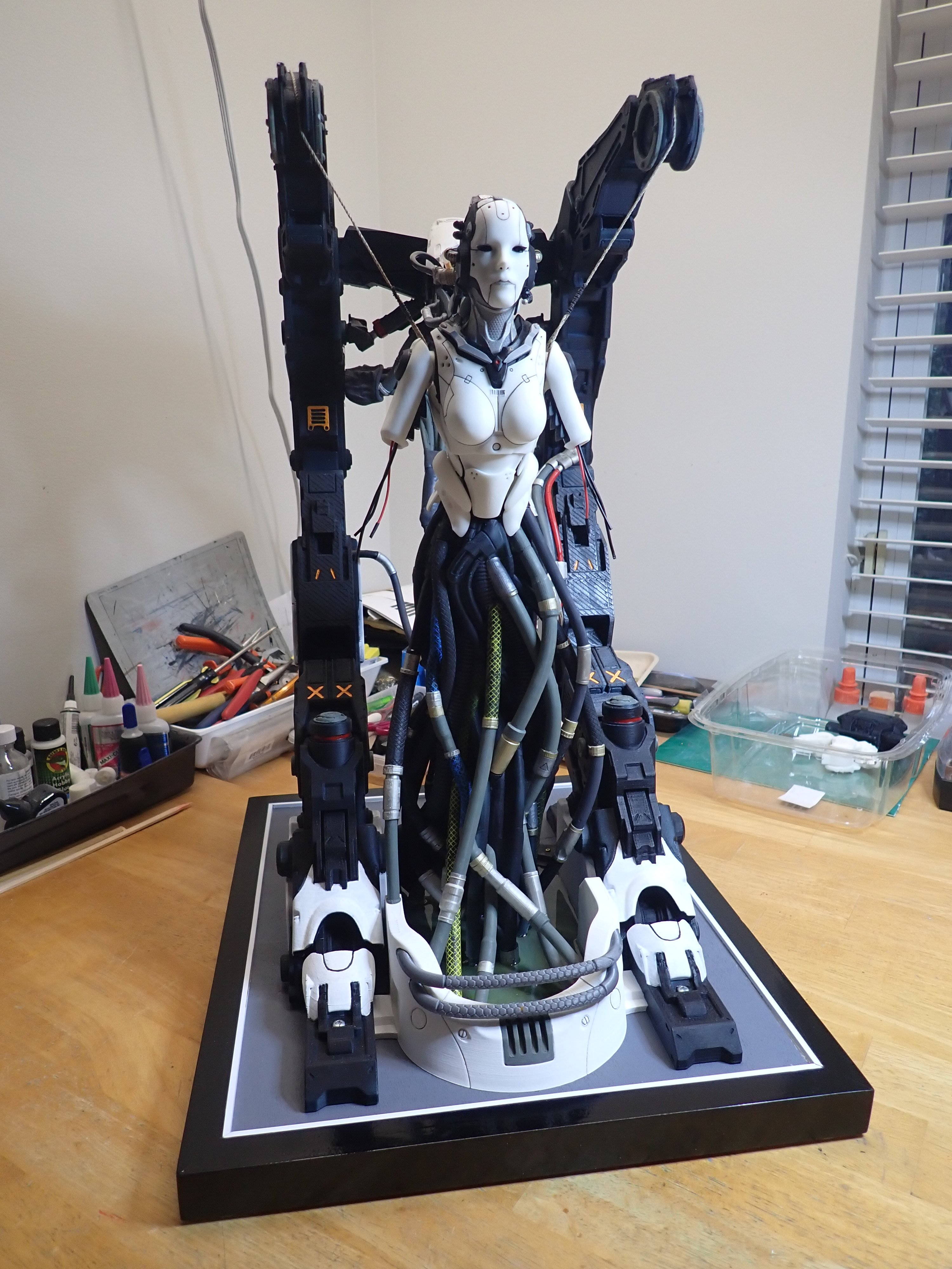
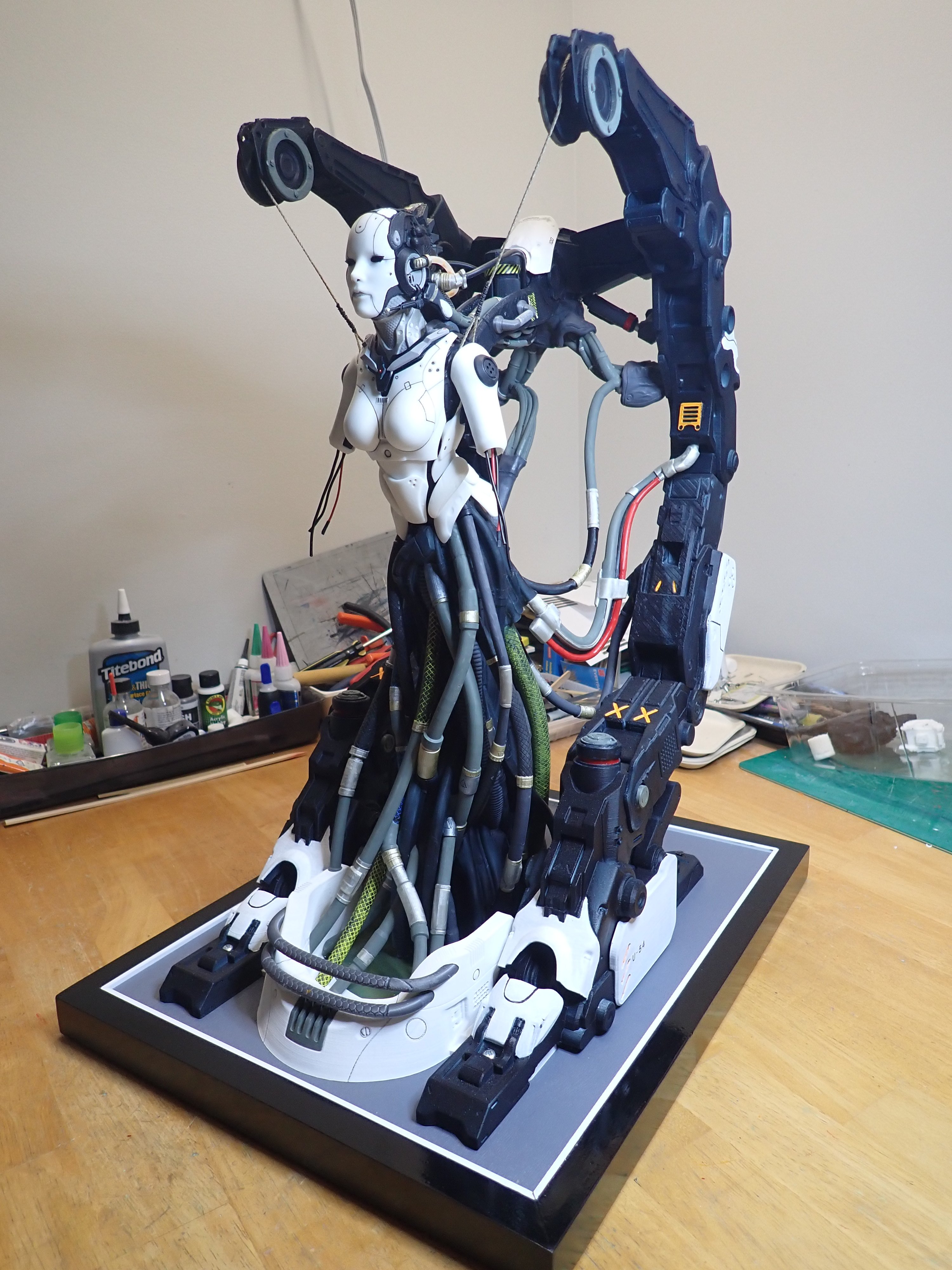
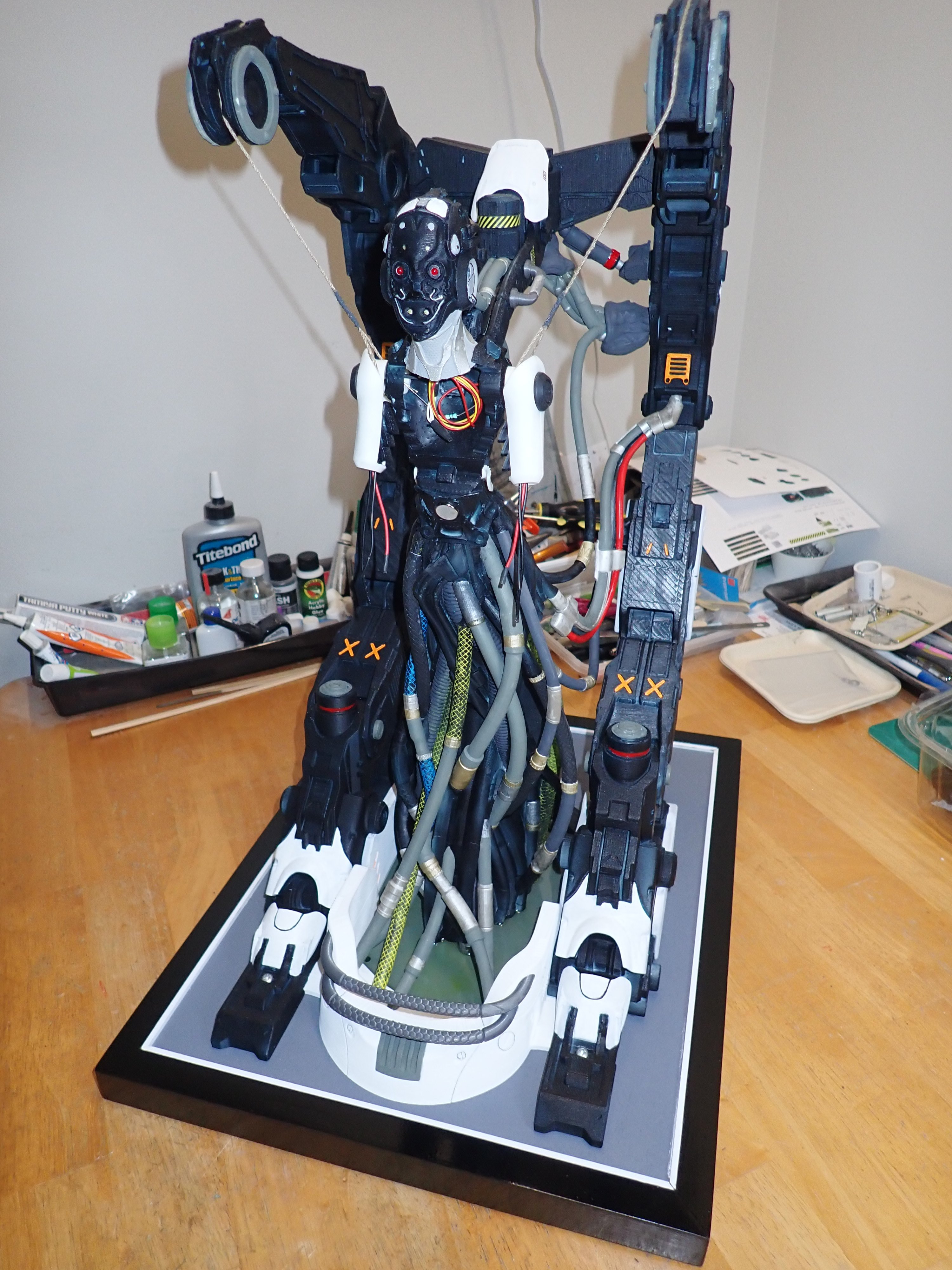
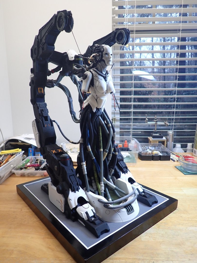
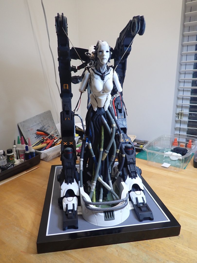
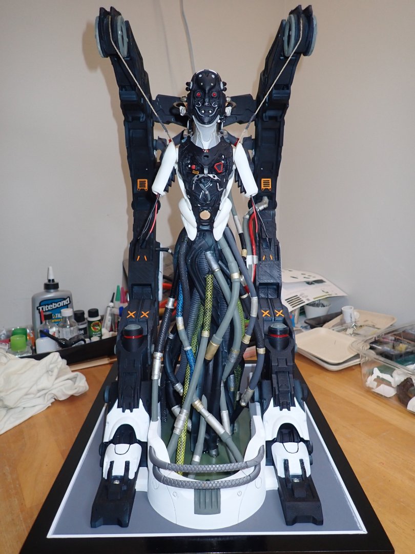
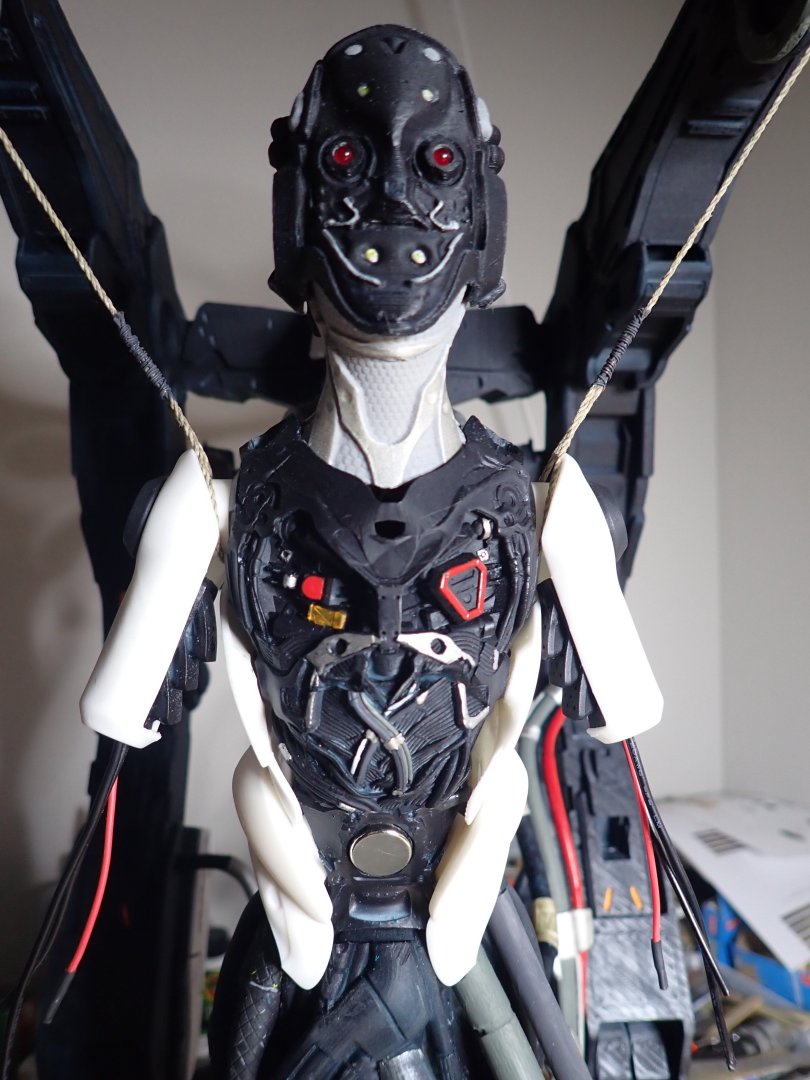
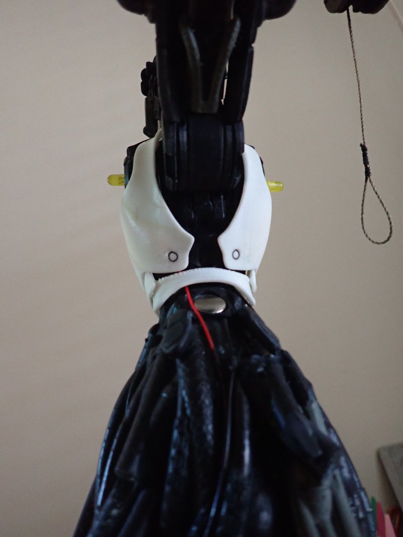
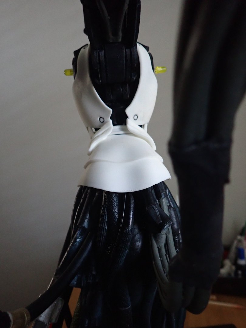
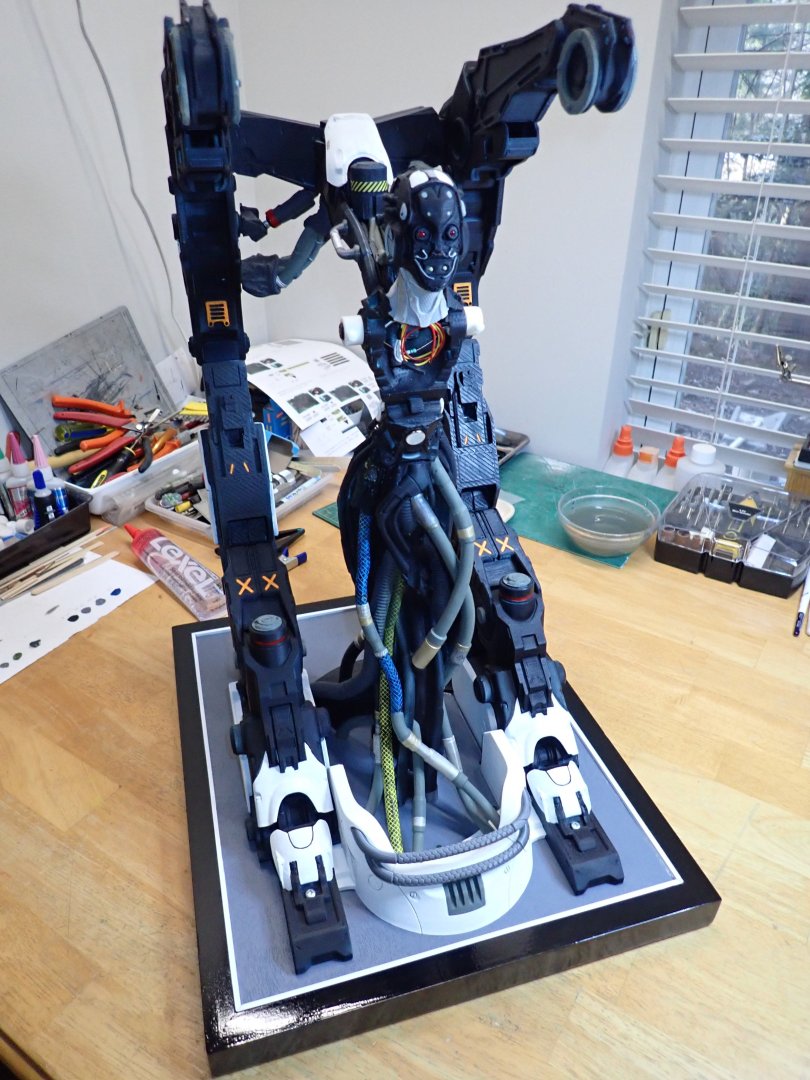
It is almost completed. The AI creature is done, neck armor painted and installed: There is still a need for finalizing the makeup of the face armor.... Overall views of the model: Et voila. The only things that remains are the installation of a rechargeable battery unit behind the hangar, to power the LEDs and the building of the screen/interface to interact with the AI. The original part was printed with filament and is kind of coarse to my liking. I will redo it, once I have re-installed my resin printer (preparing a move...). More to come.... Yves


-
Bentley Blower by RGL - Airfix - 1/12 - PLASTIC
yvesvidal replied to RGL's topic in Non-ship/categorised builds
Greg, your work as always, is incredible of realism and perfection. This will be my go to Build Log, when I start the kit in my stash. Yves -
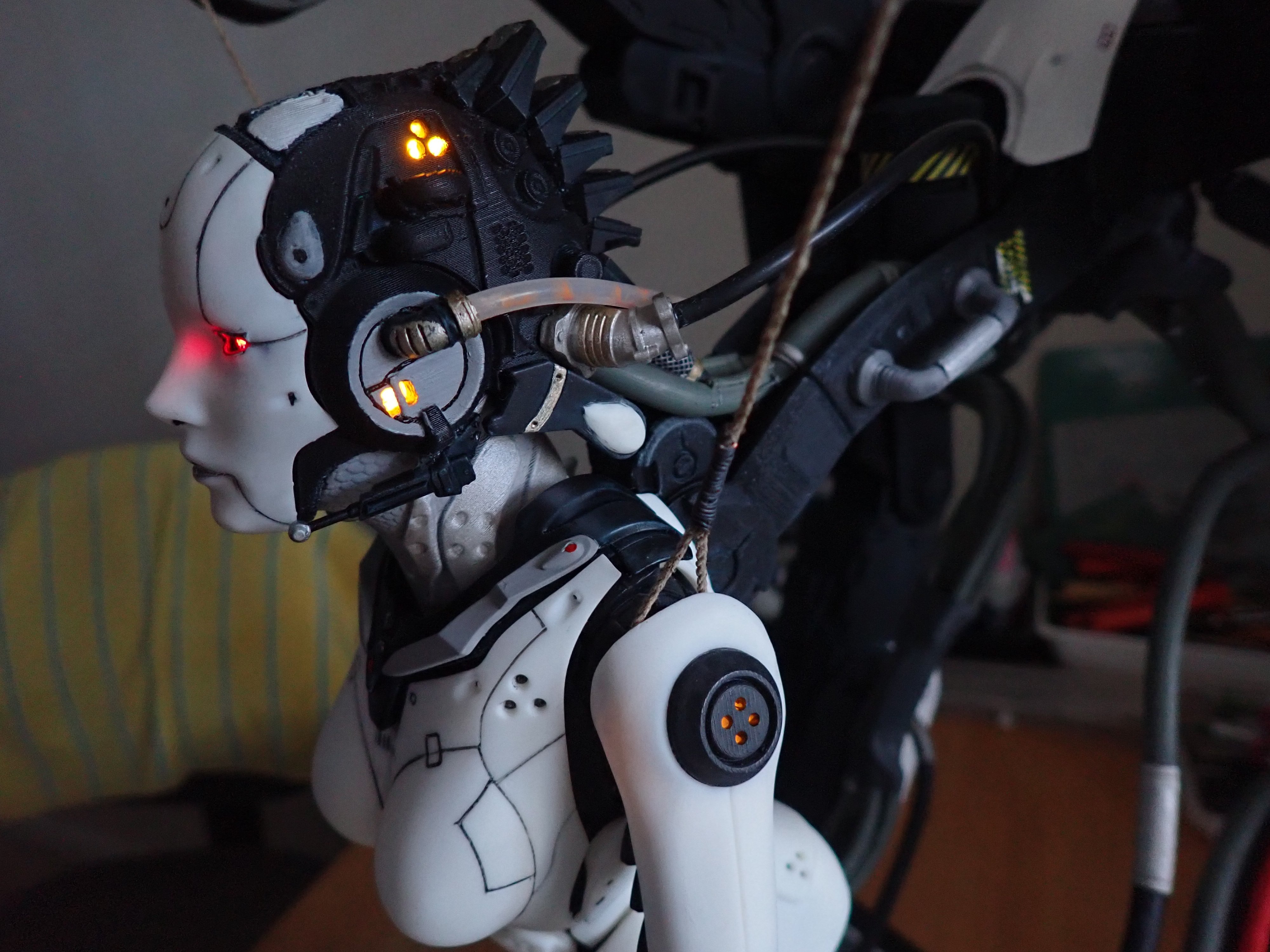
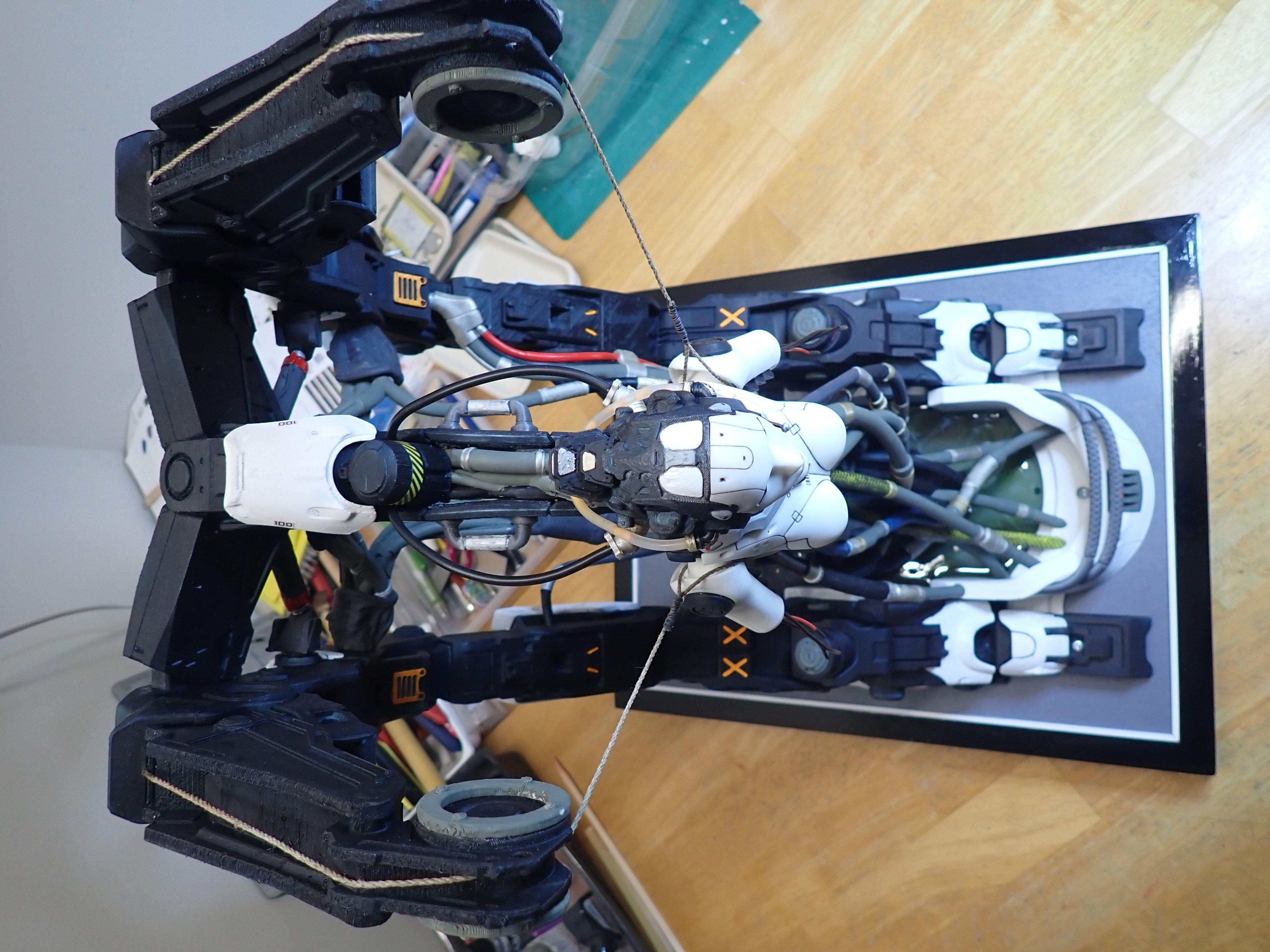
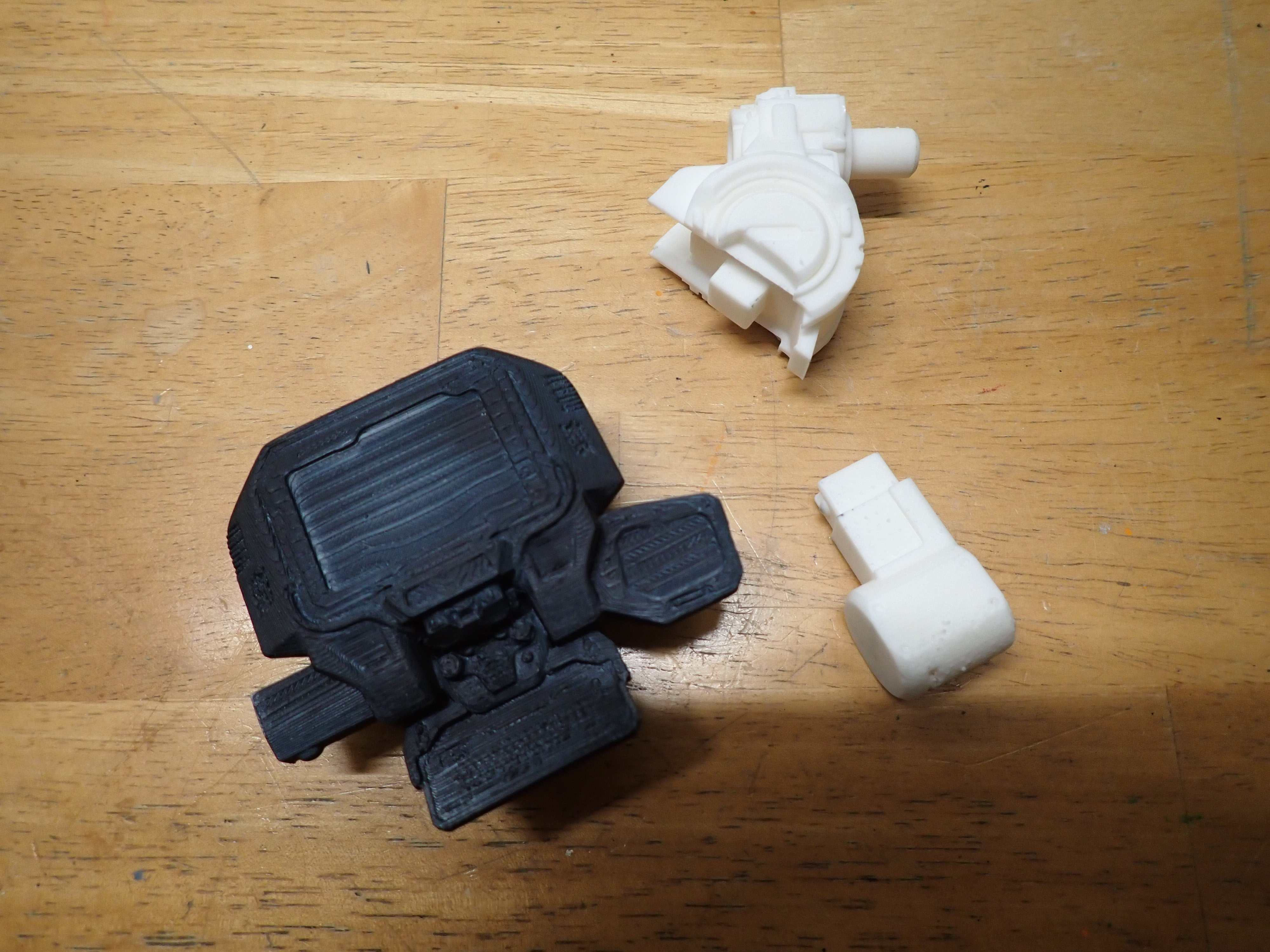
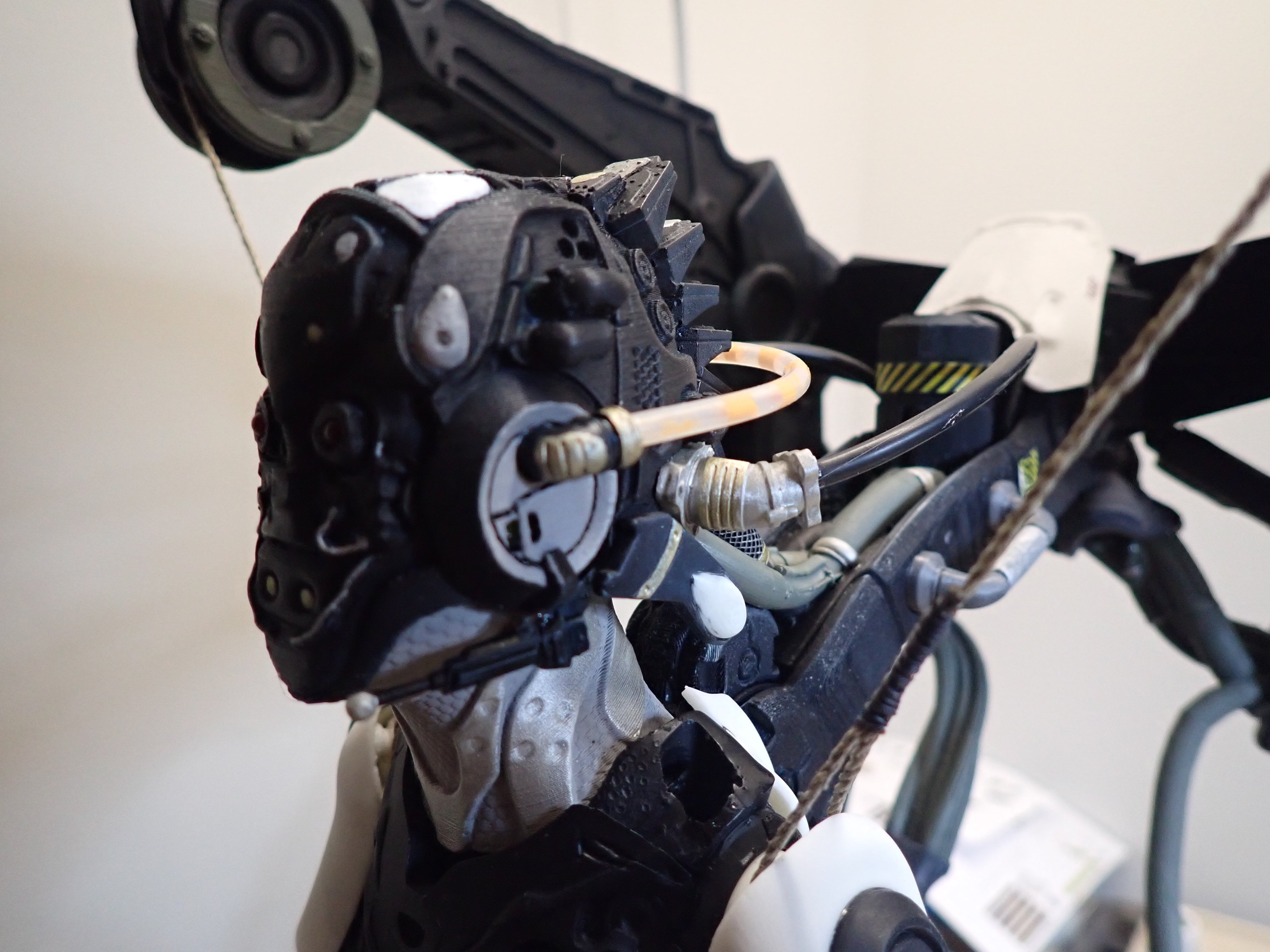
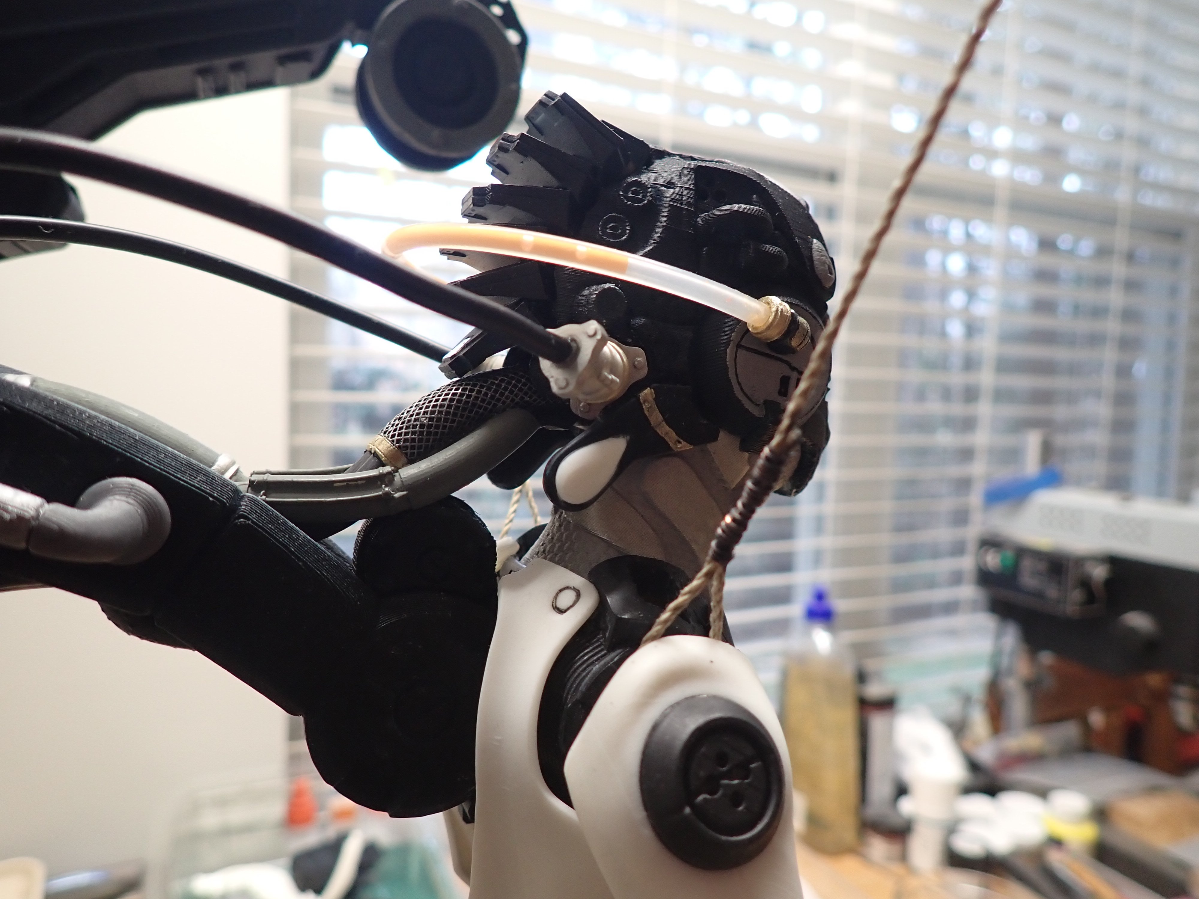
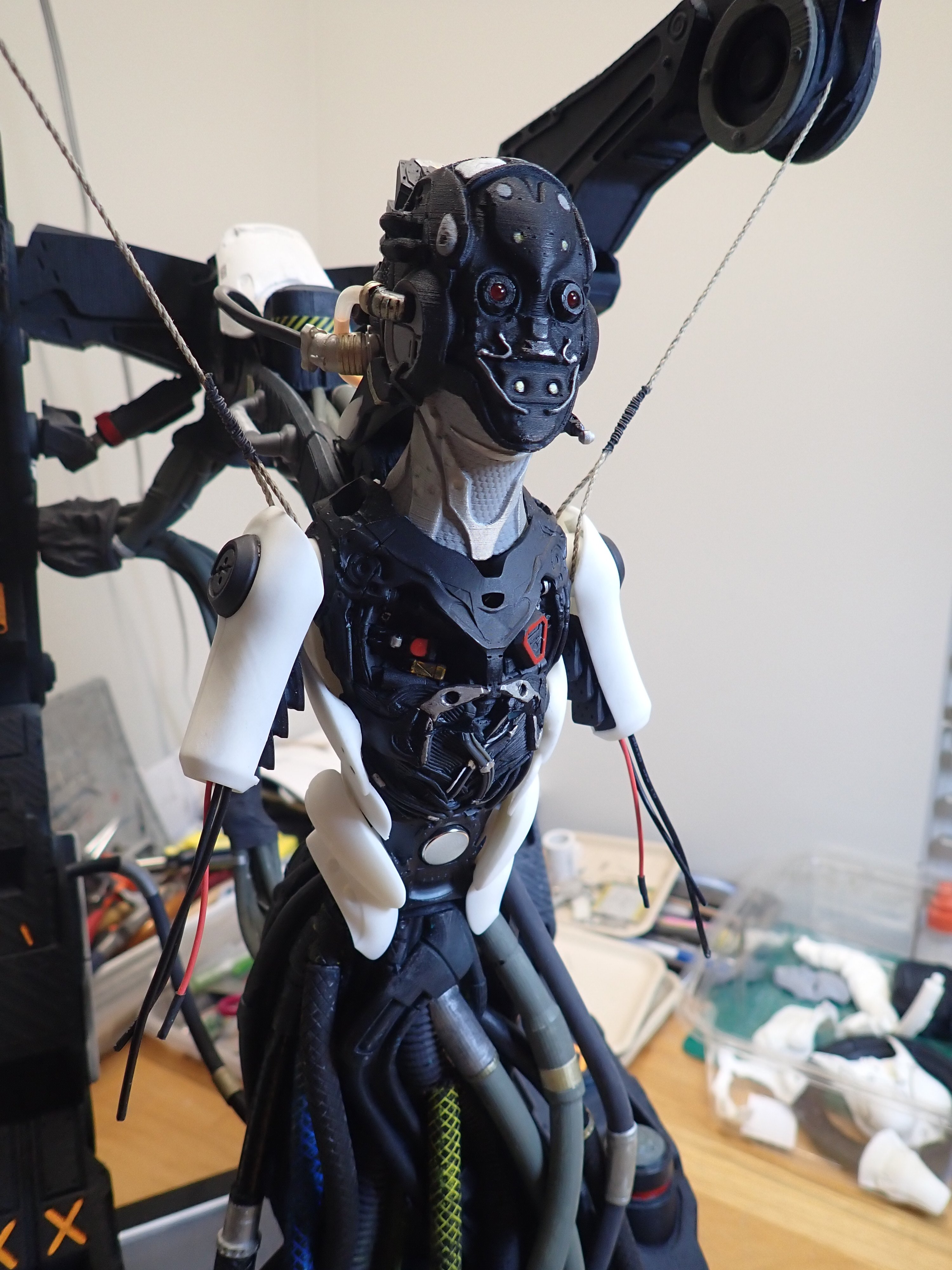
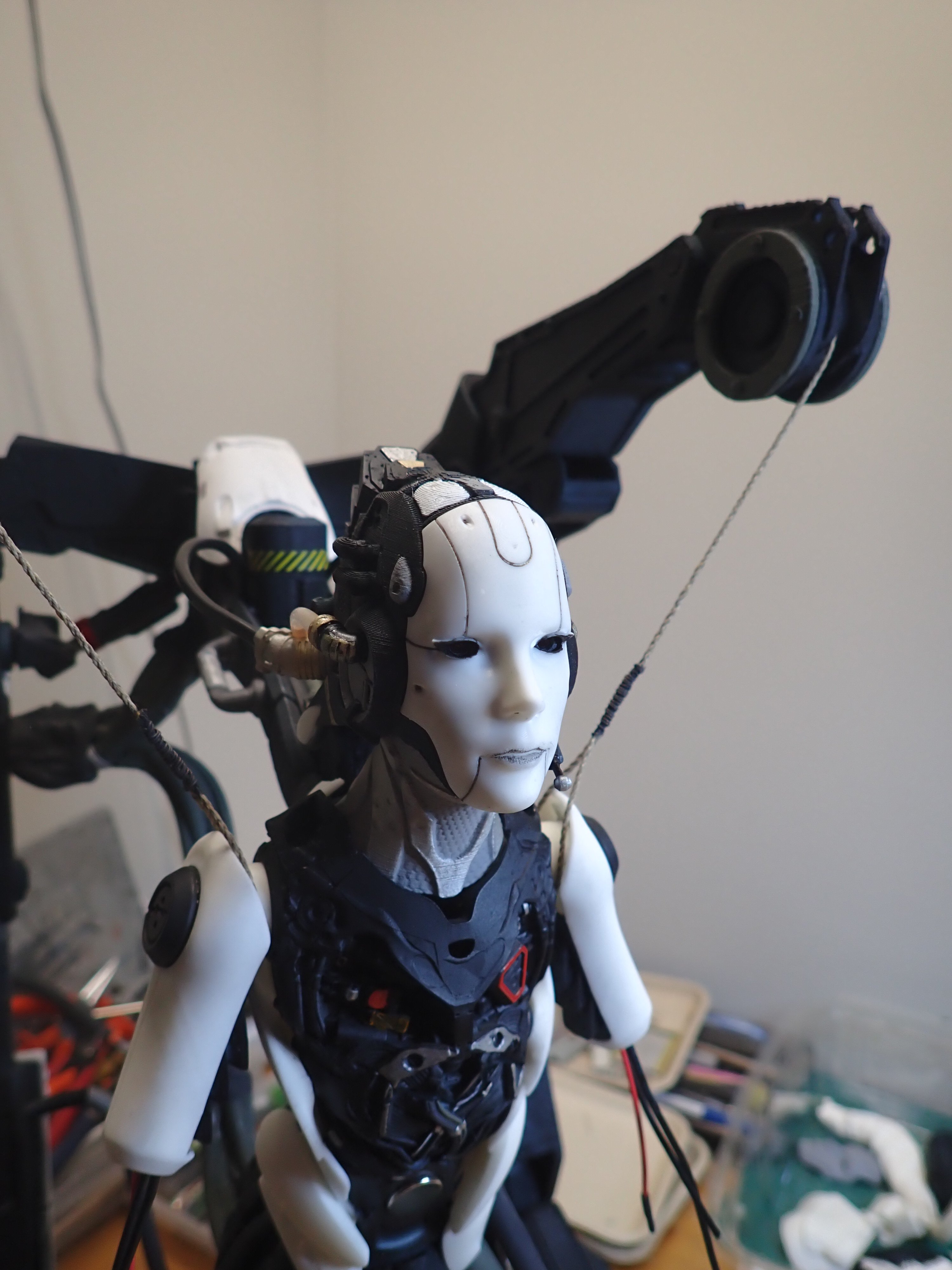
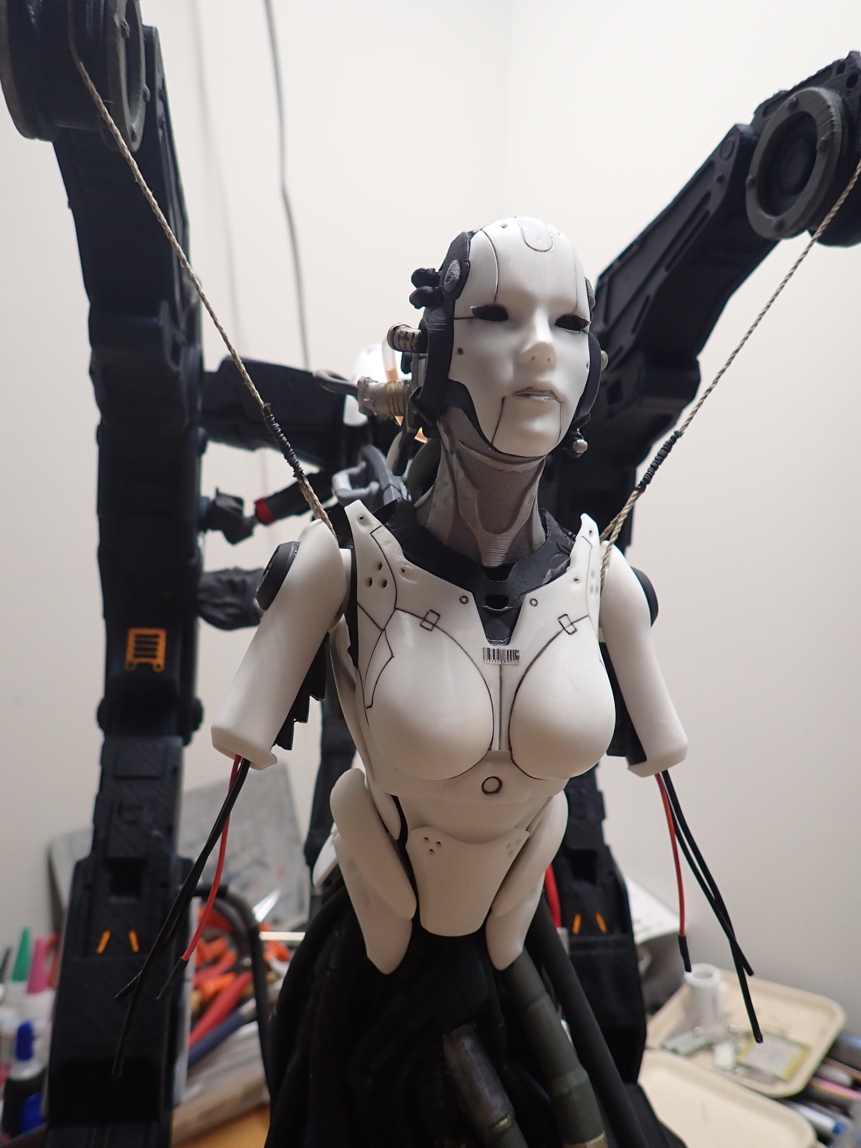
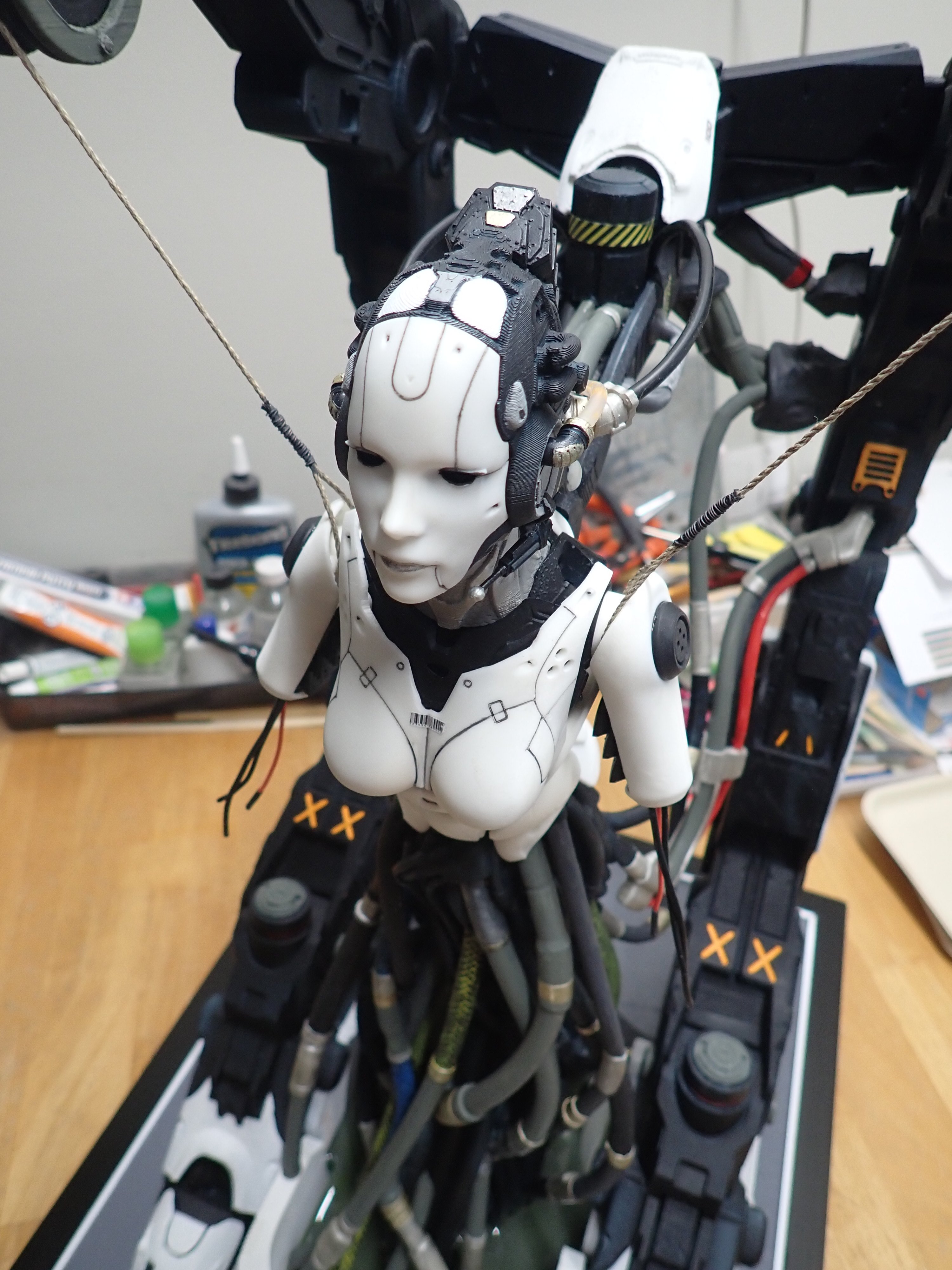
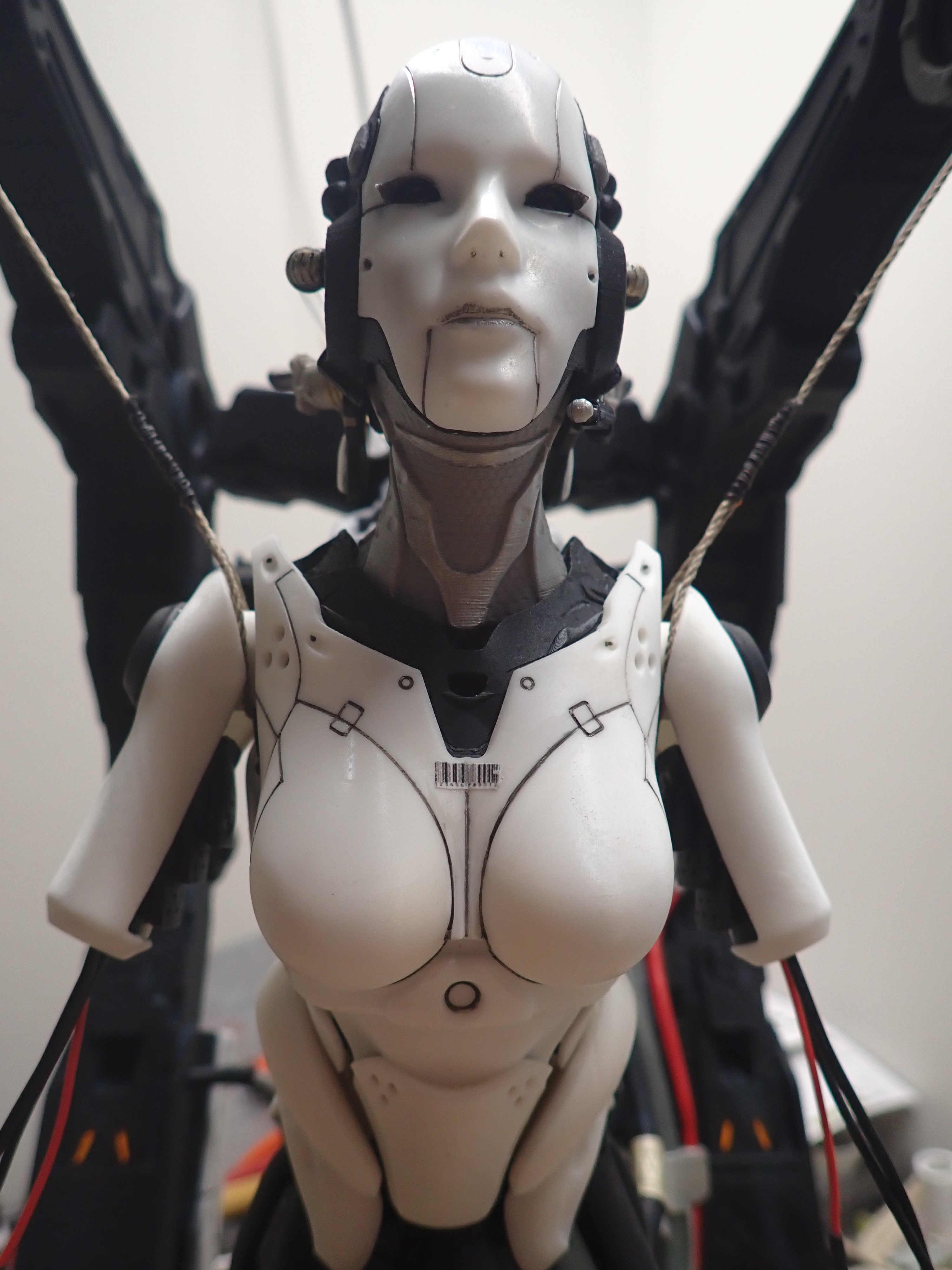
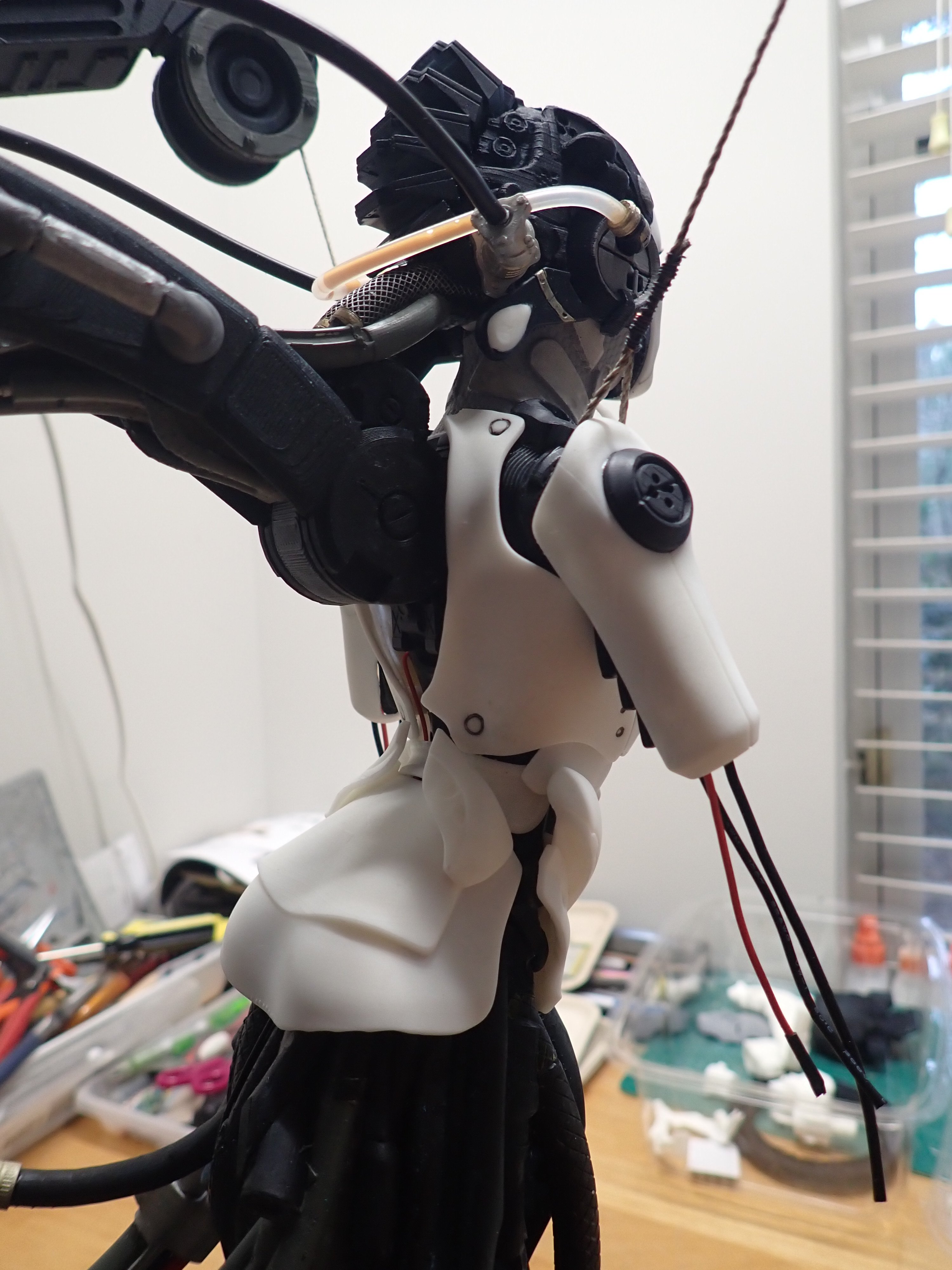
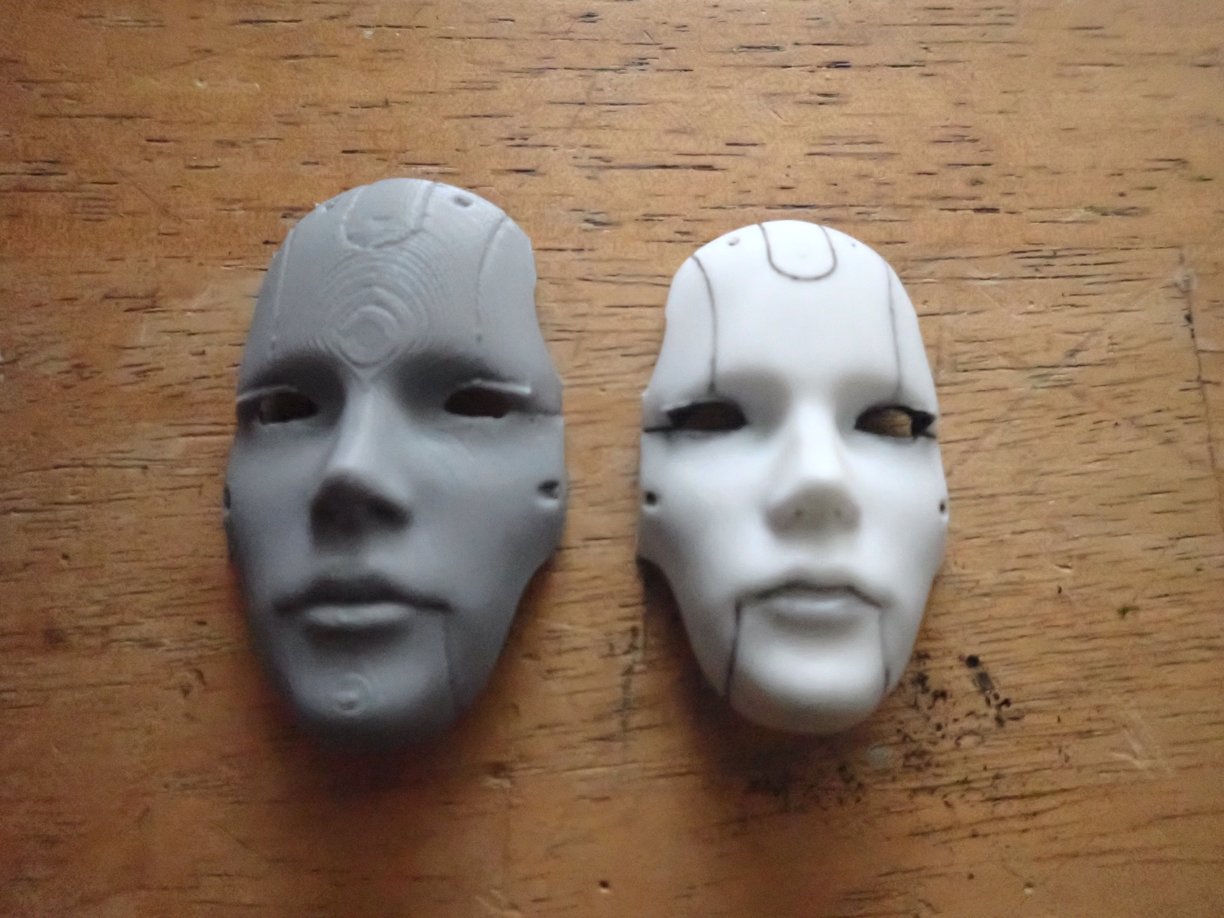
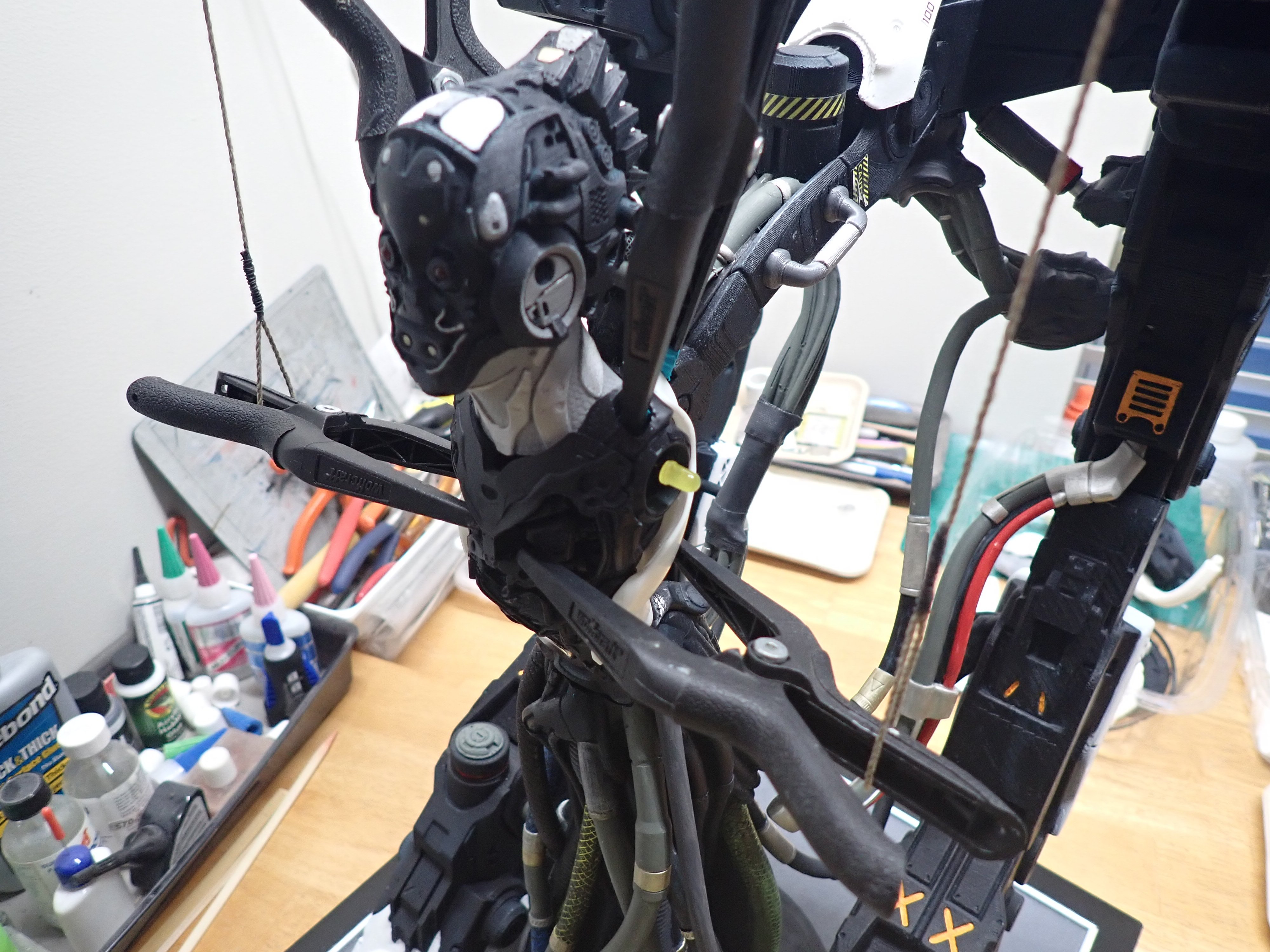
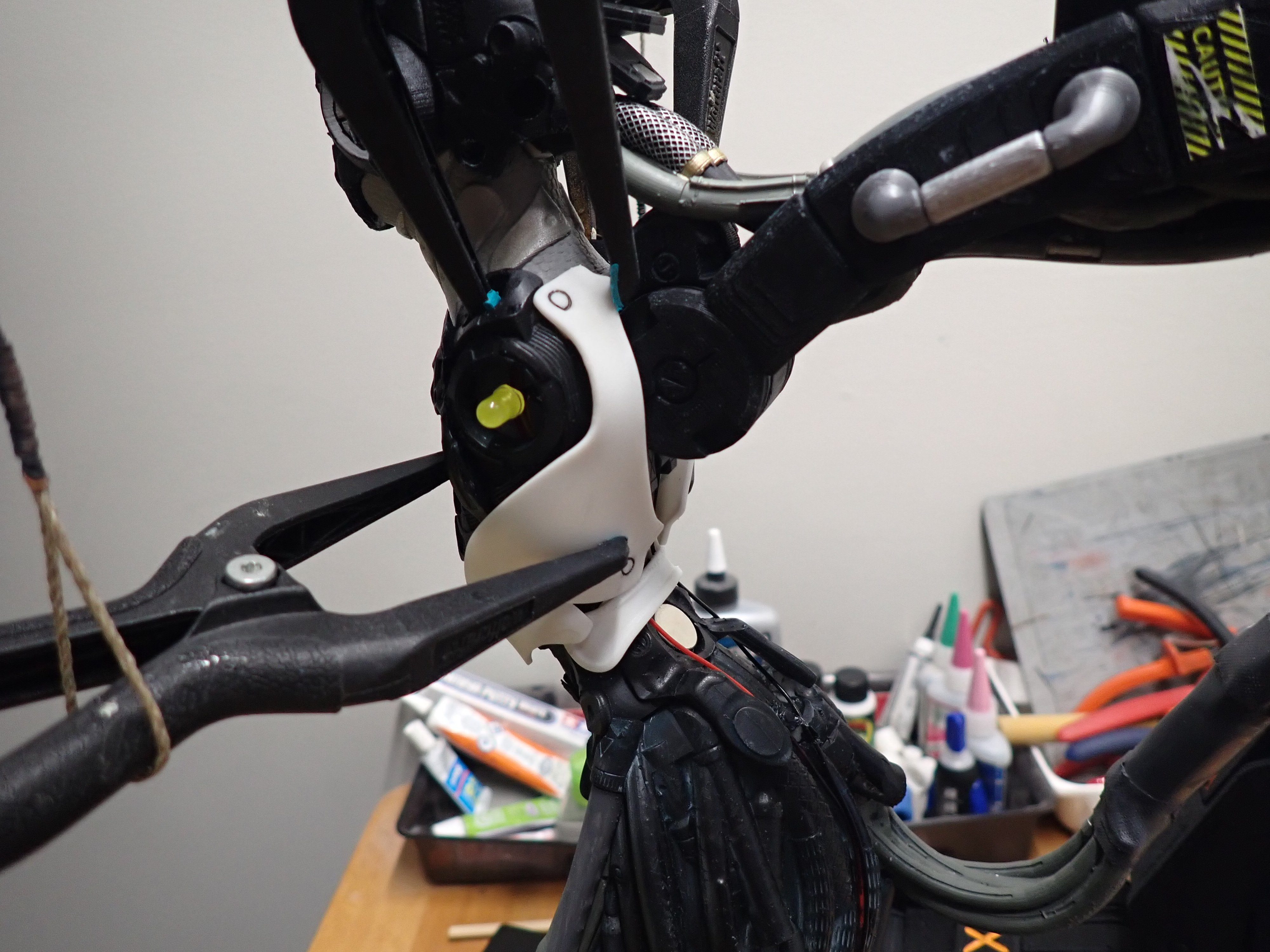
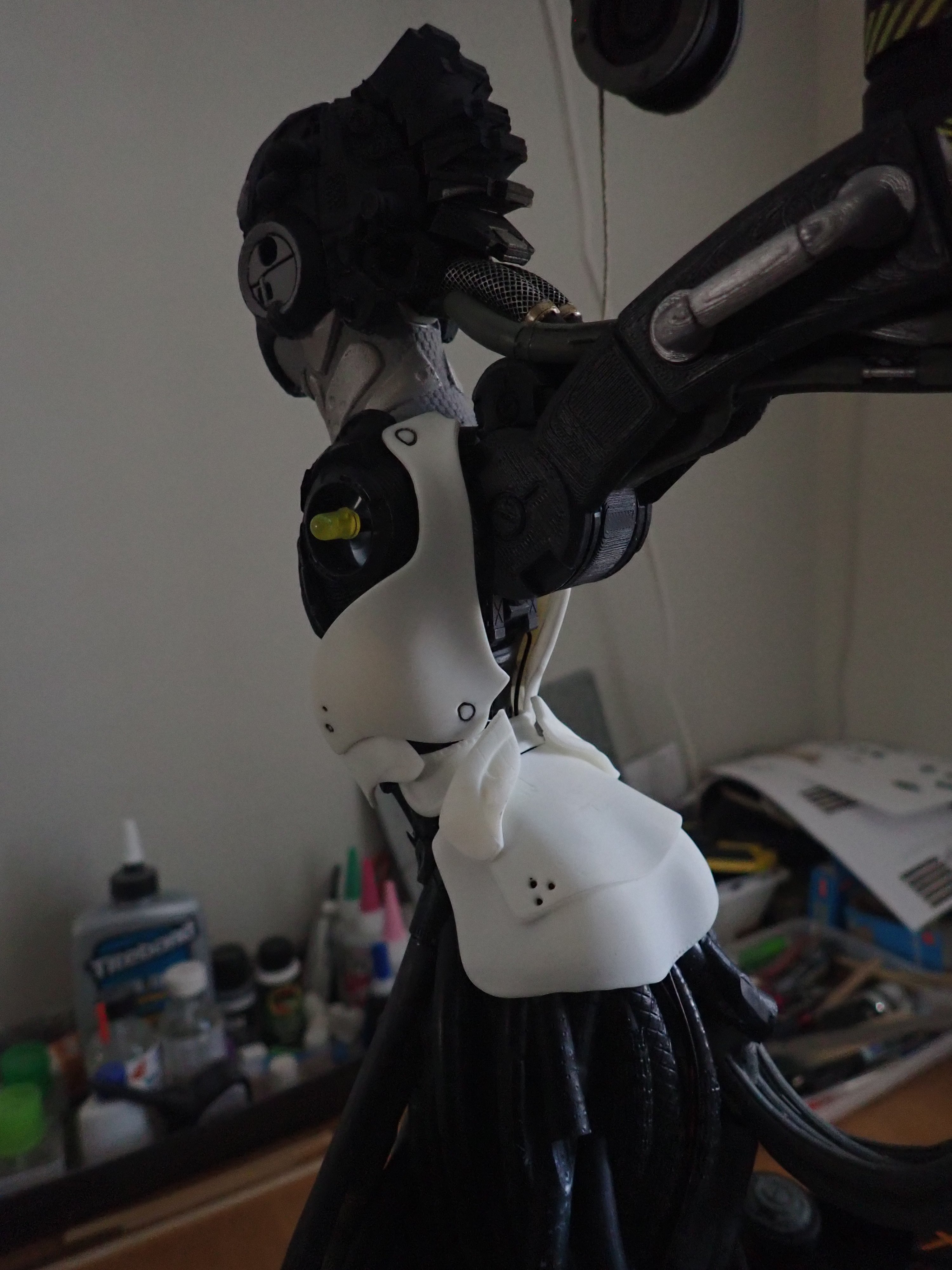
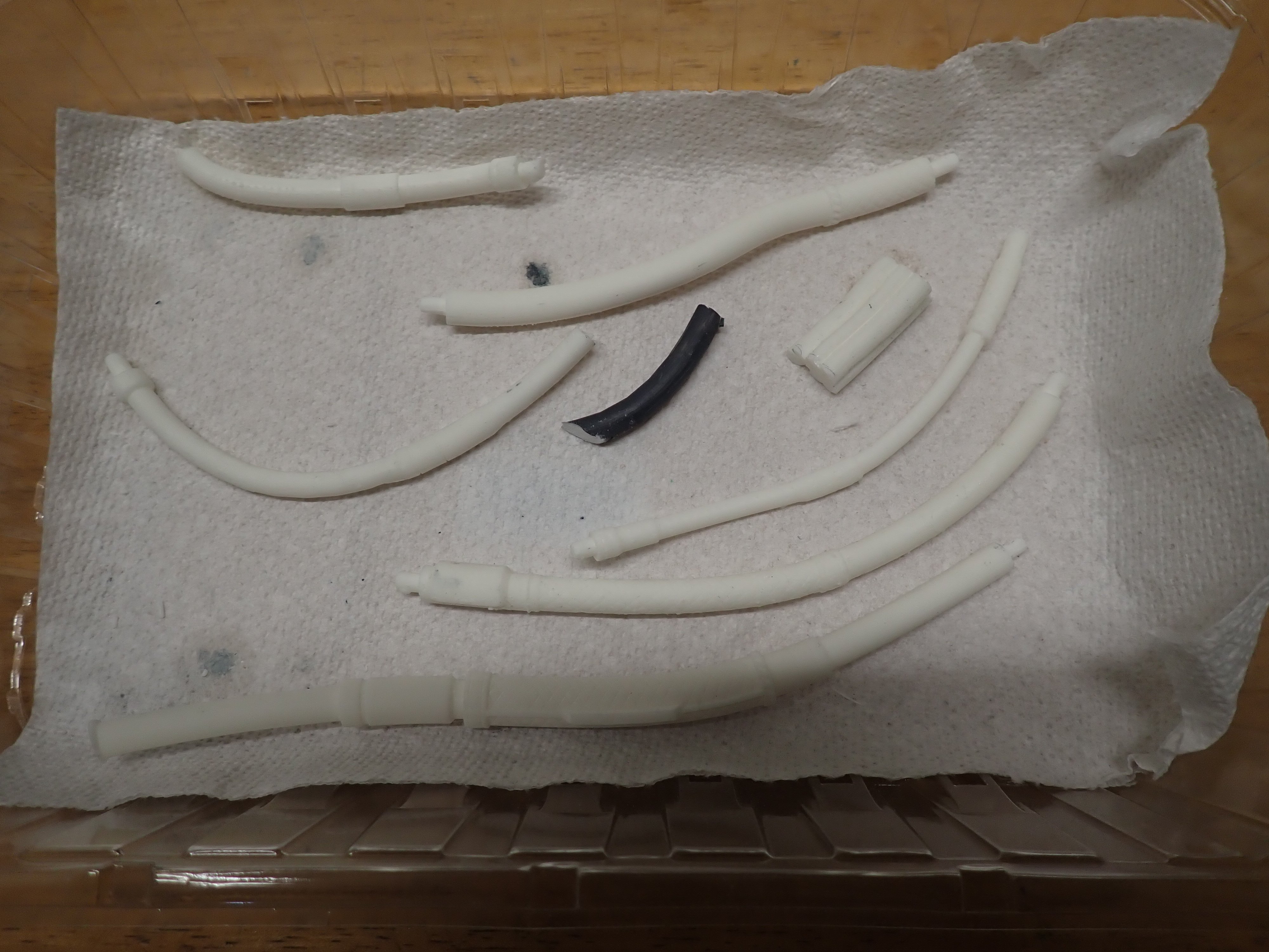
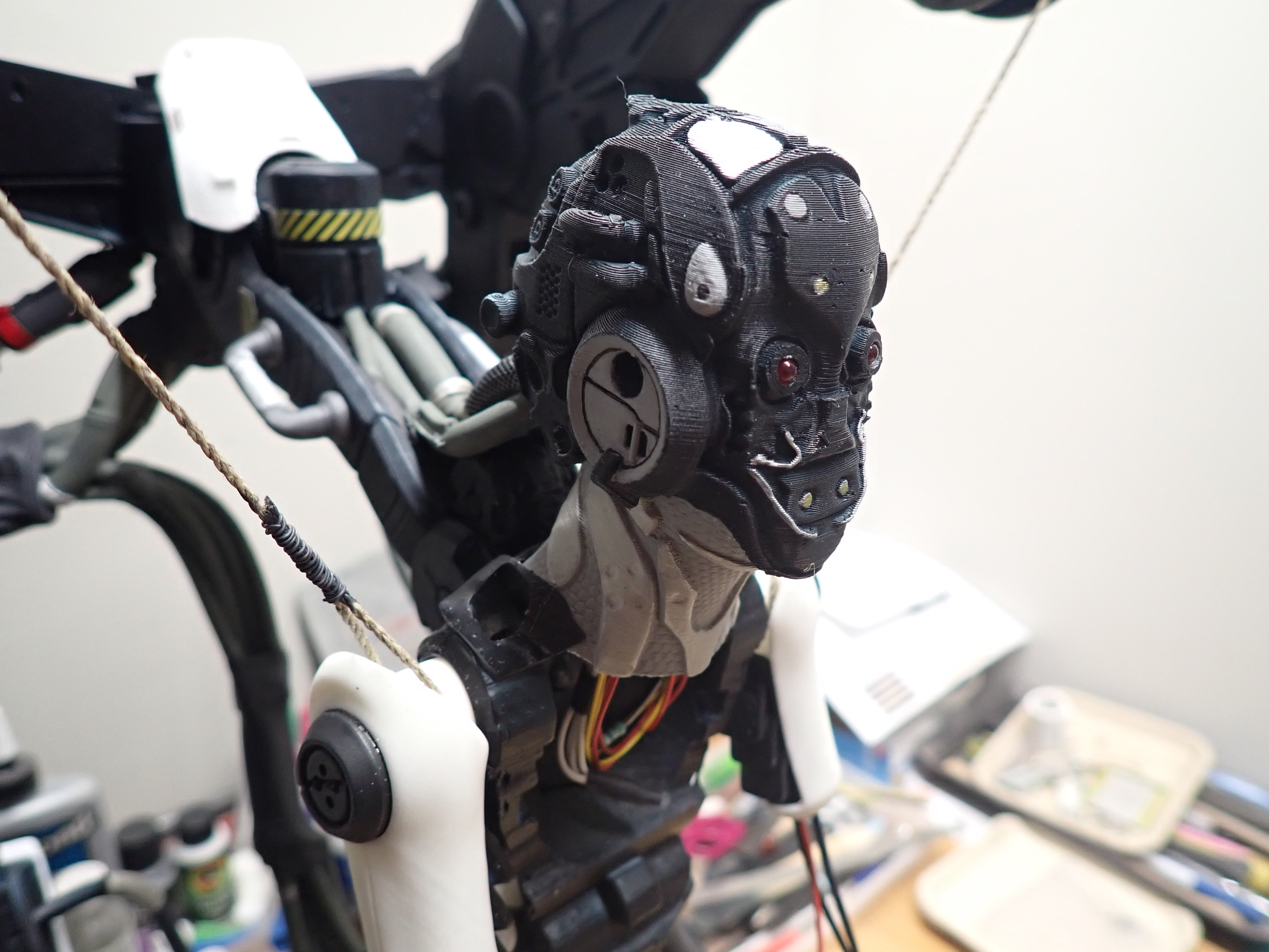
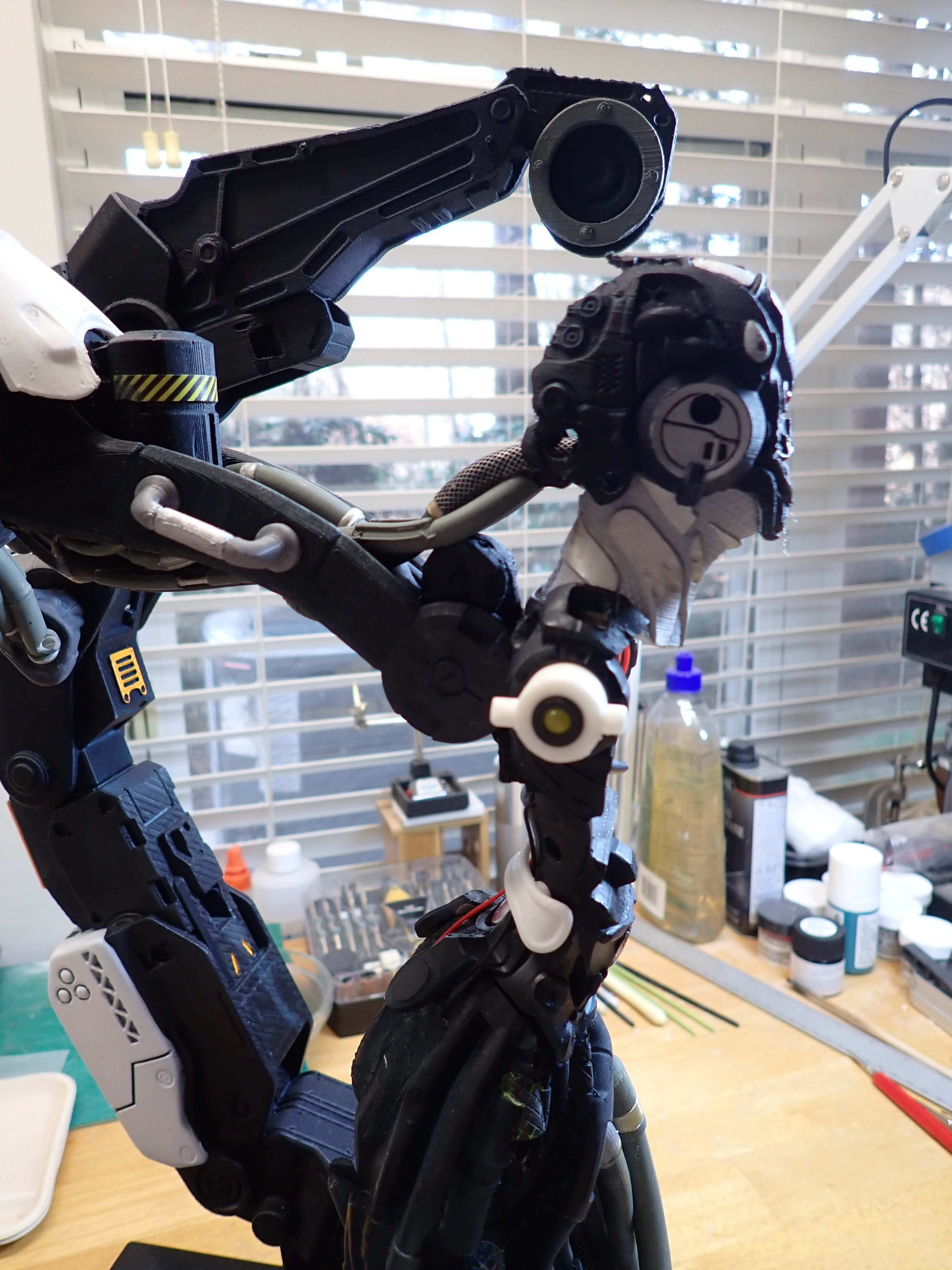
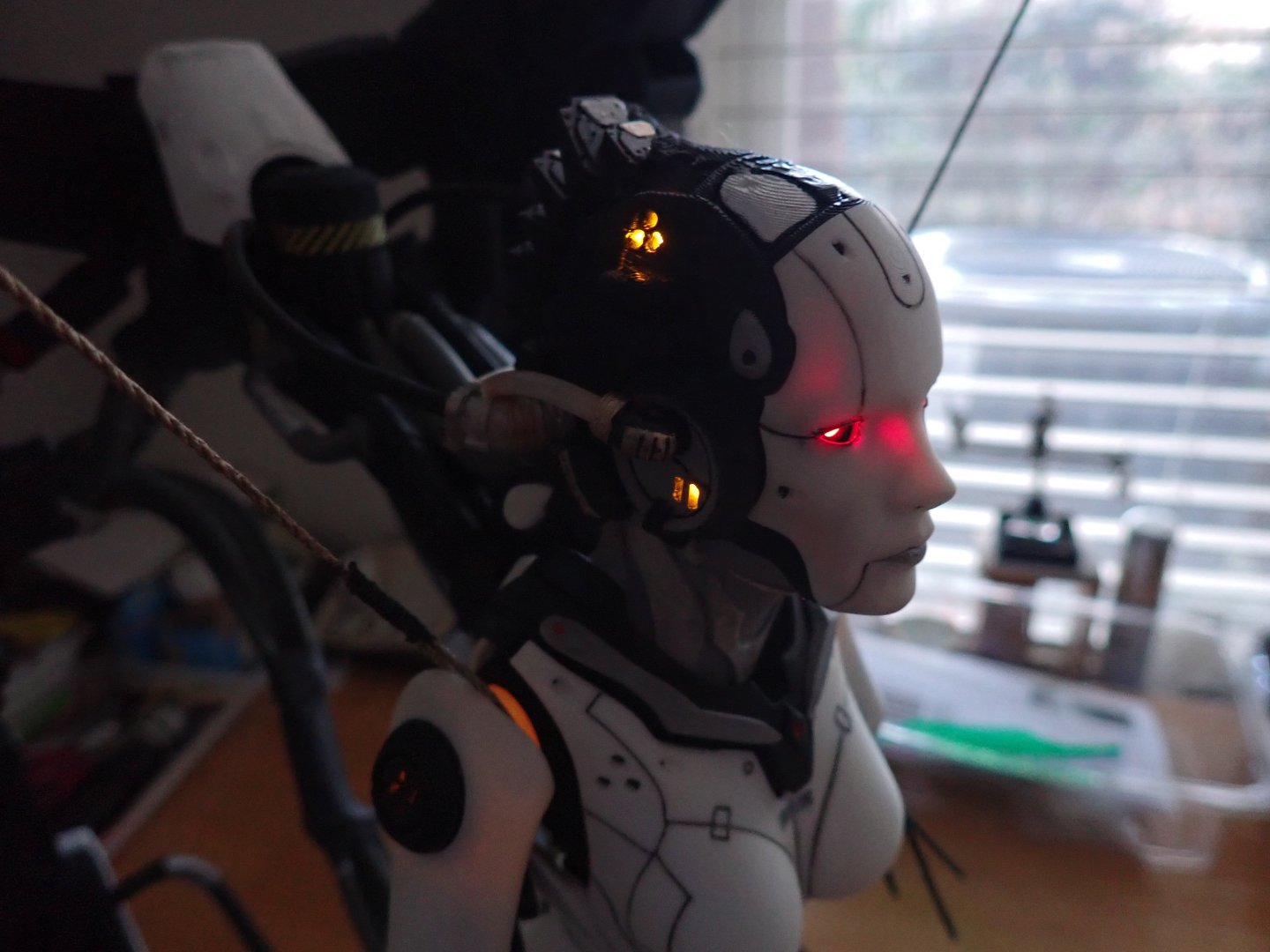
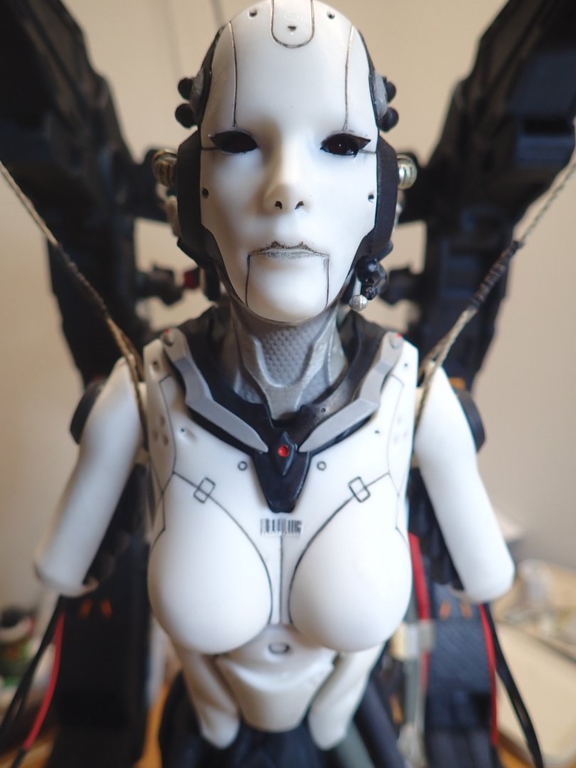
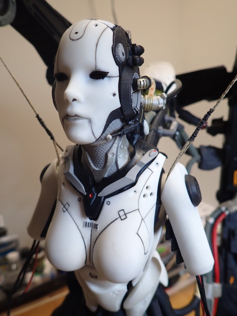
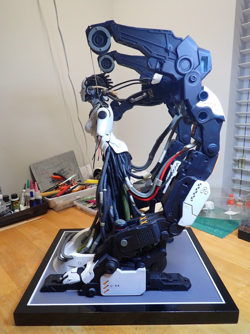
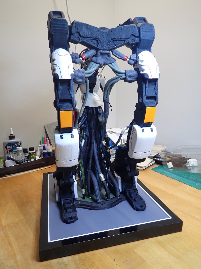
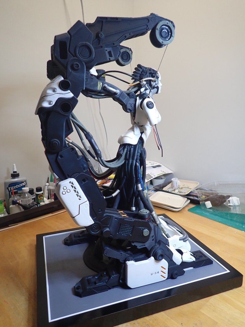
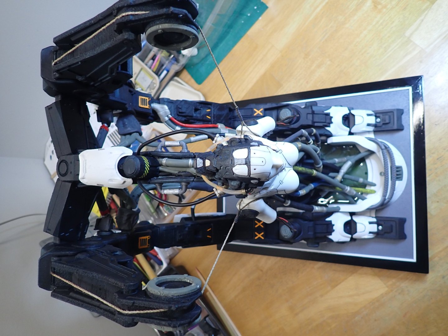
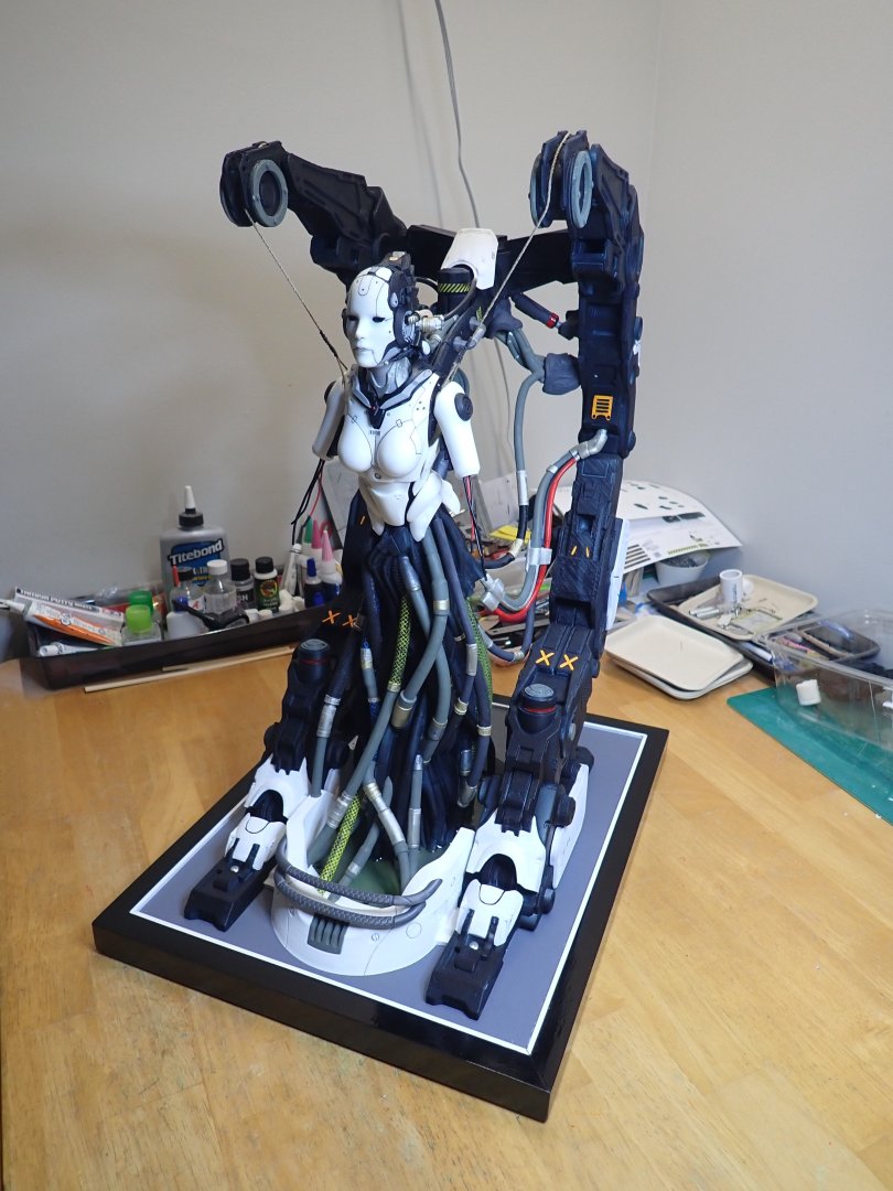
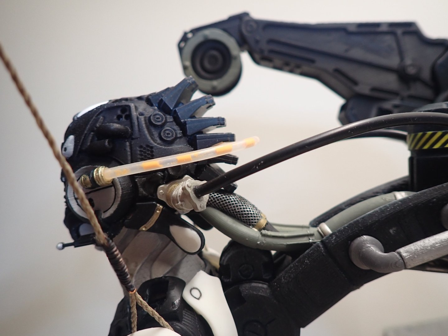
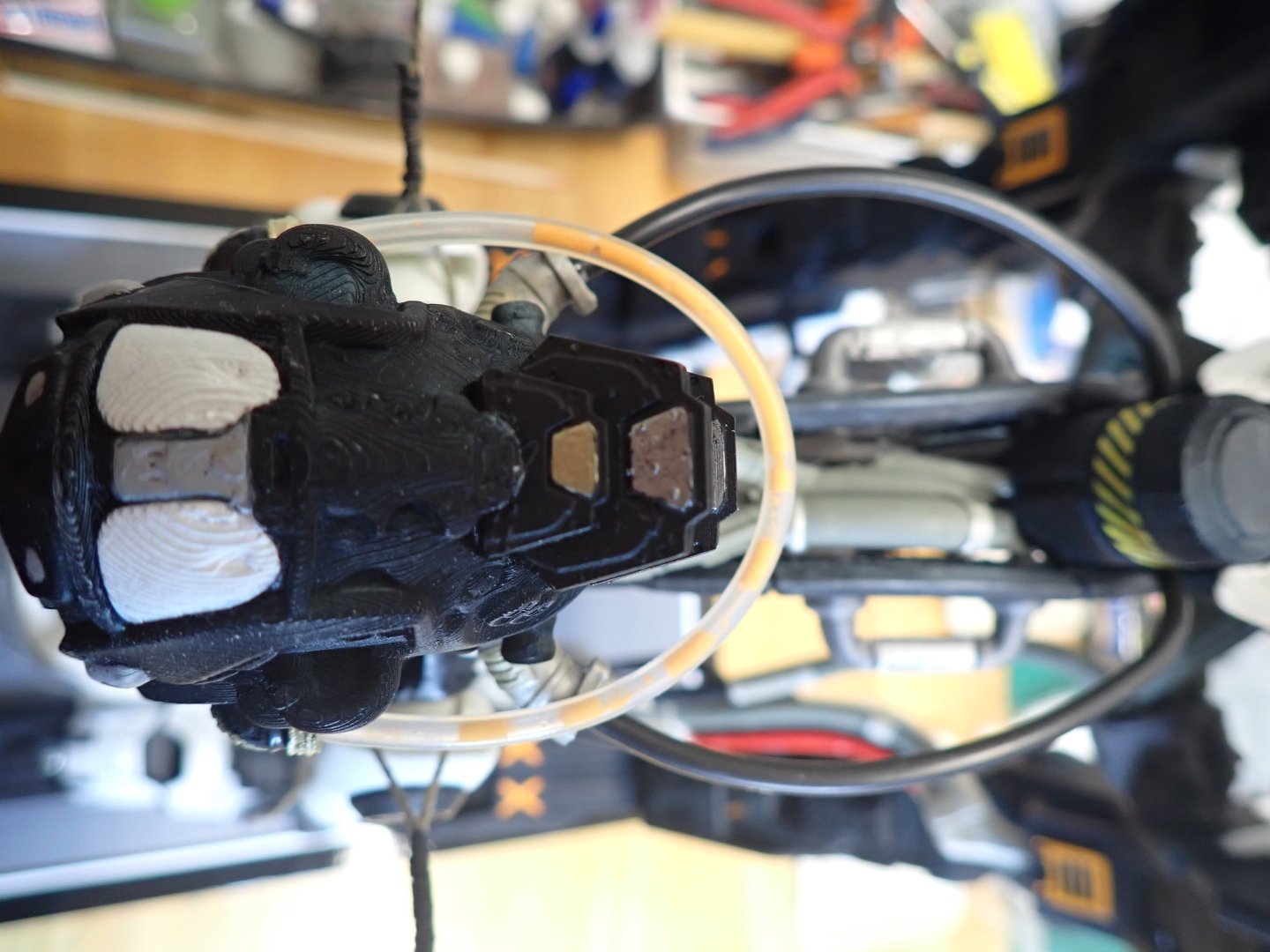
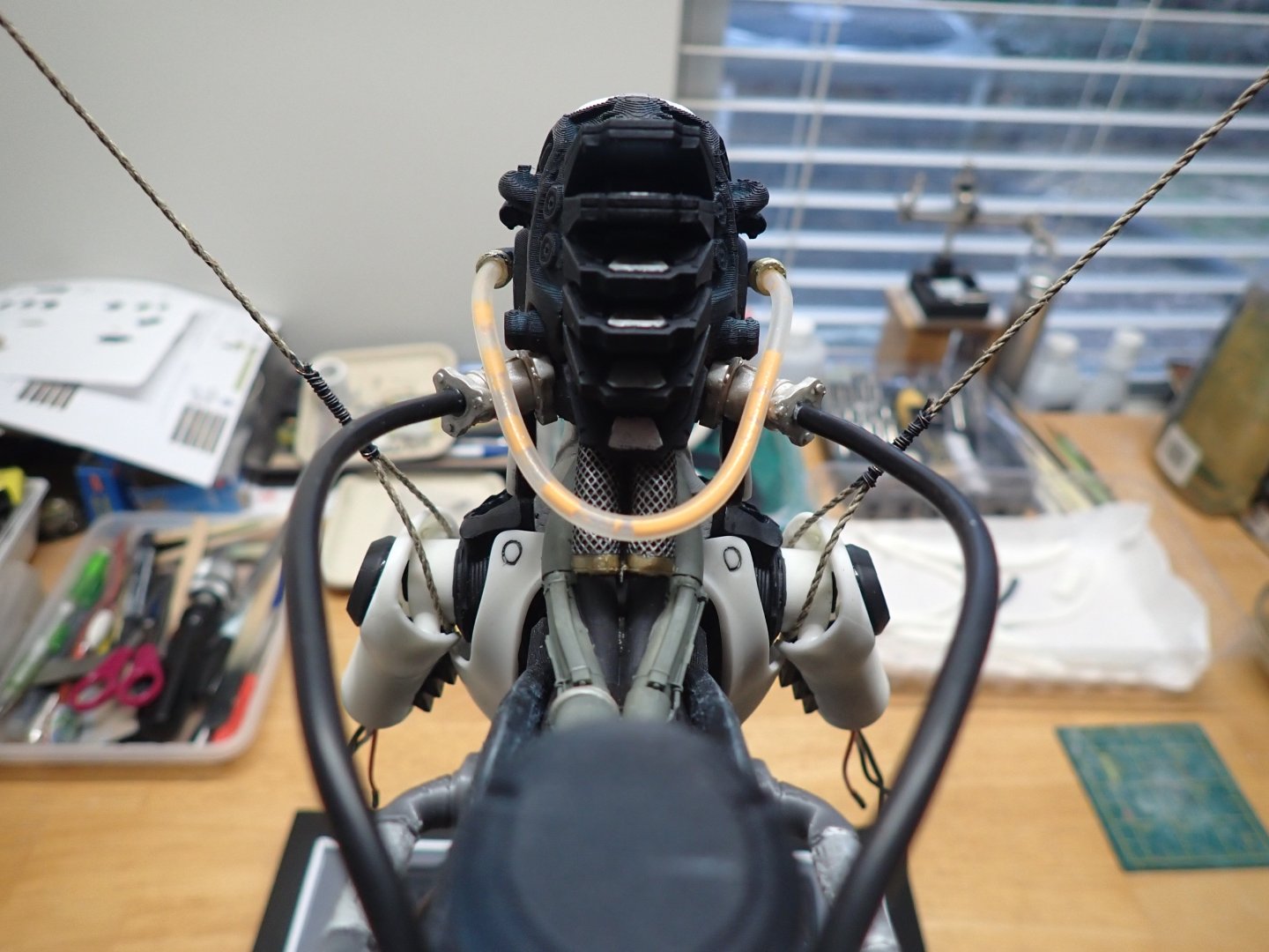
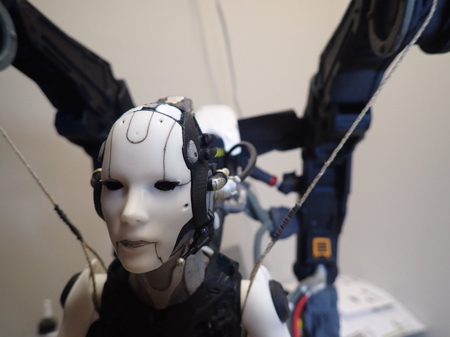
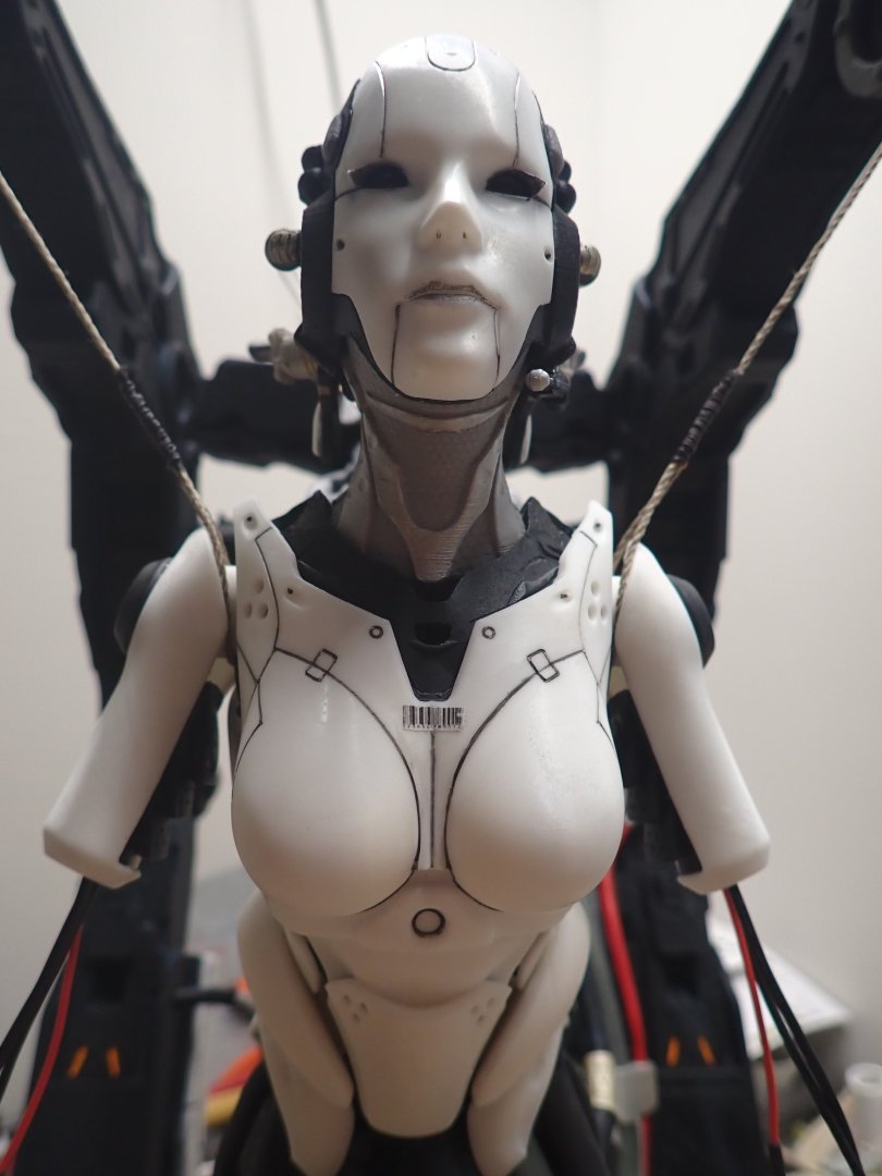
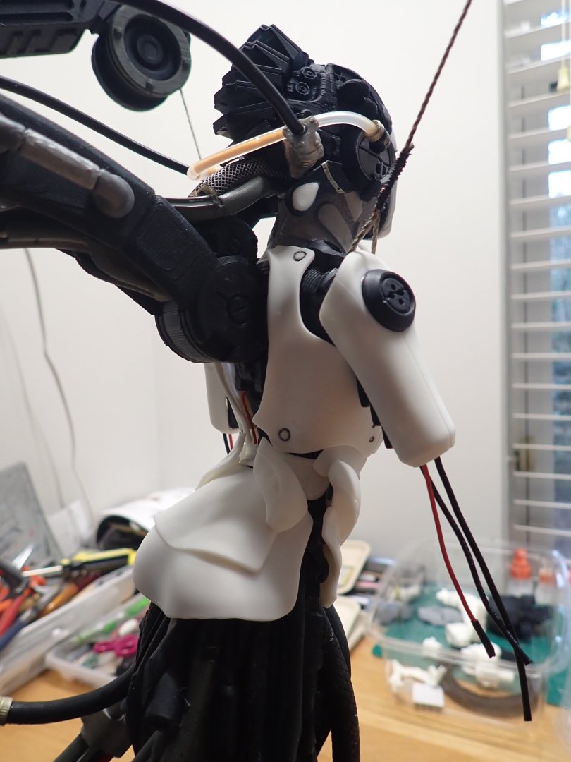
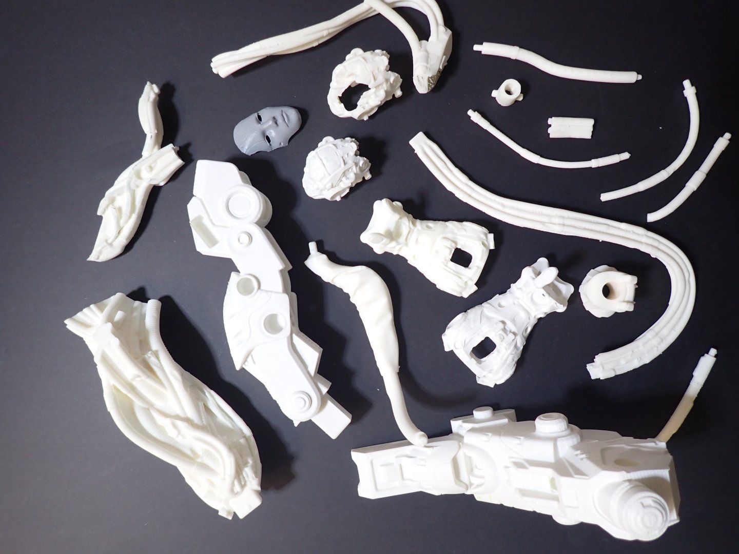
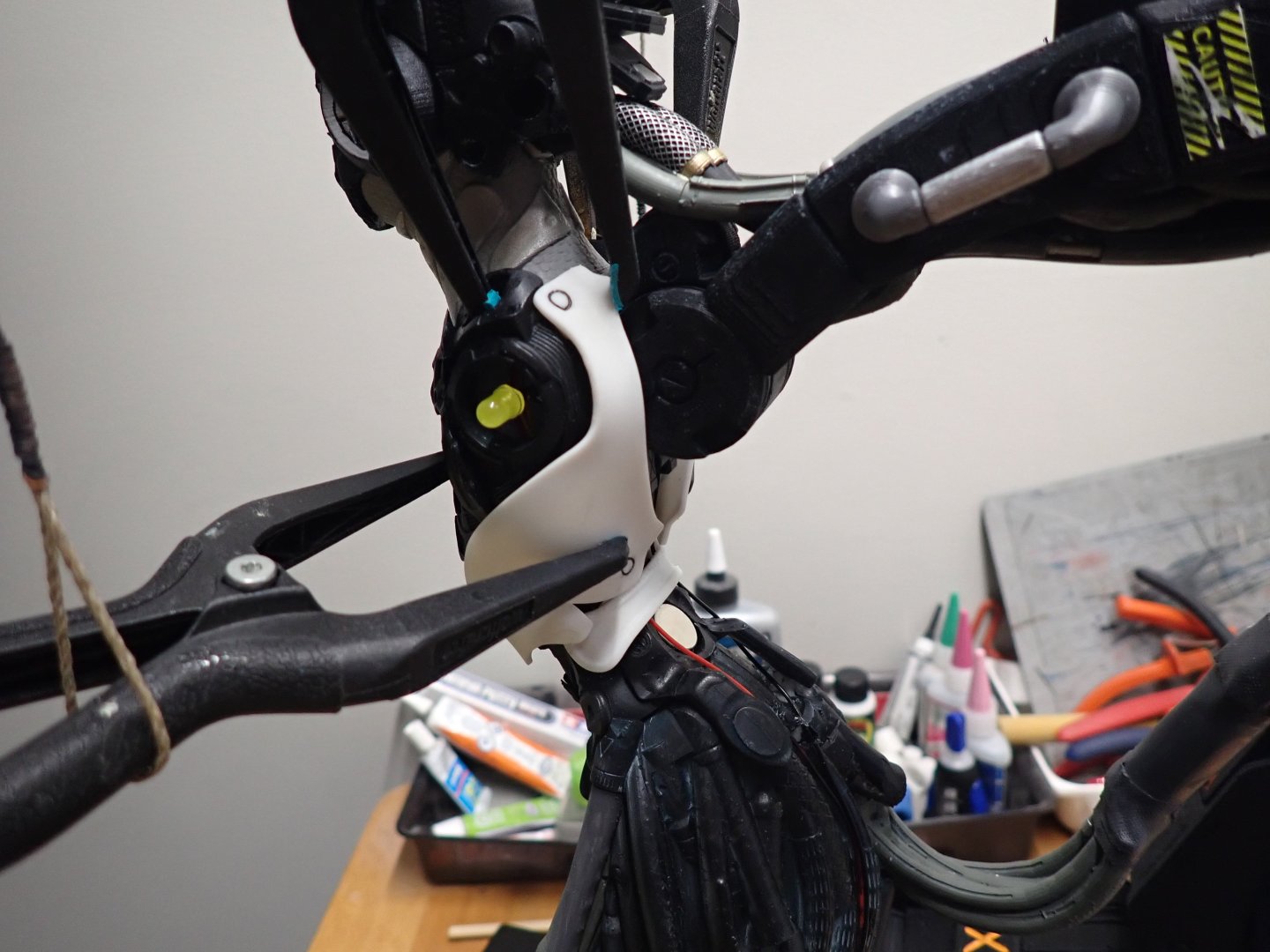
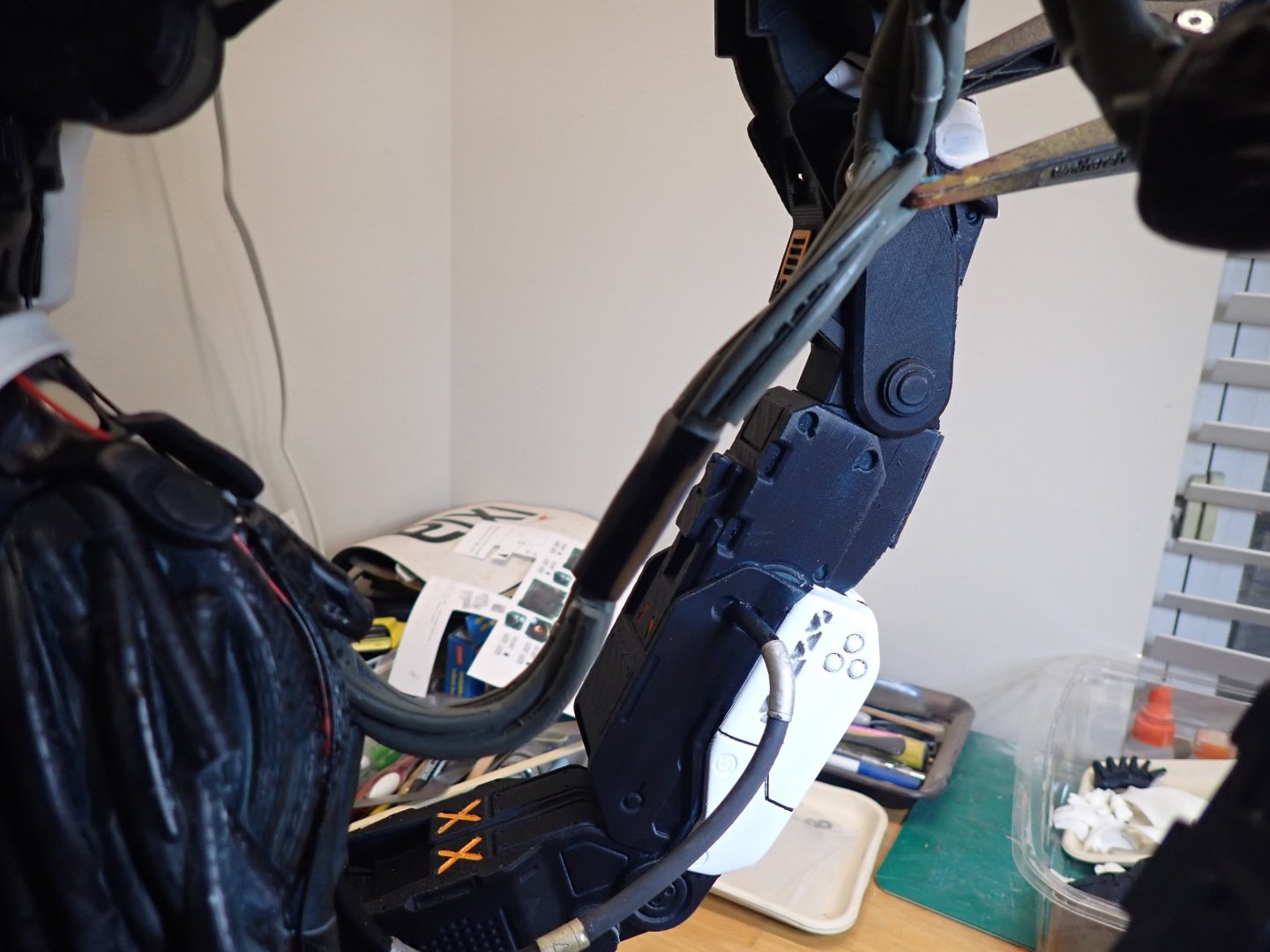
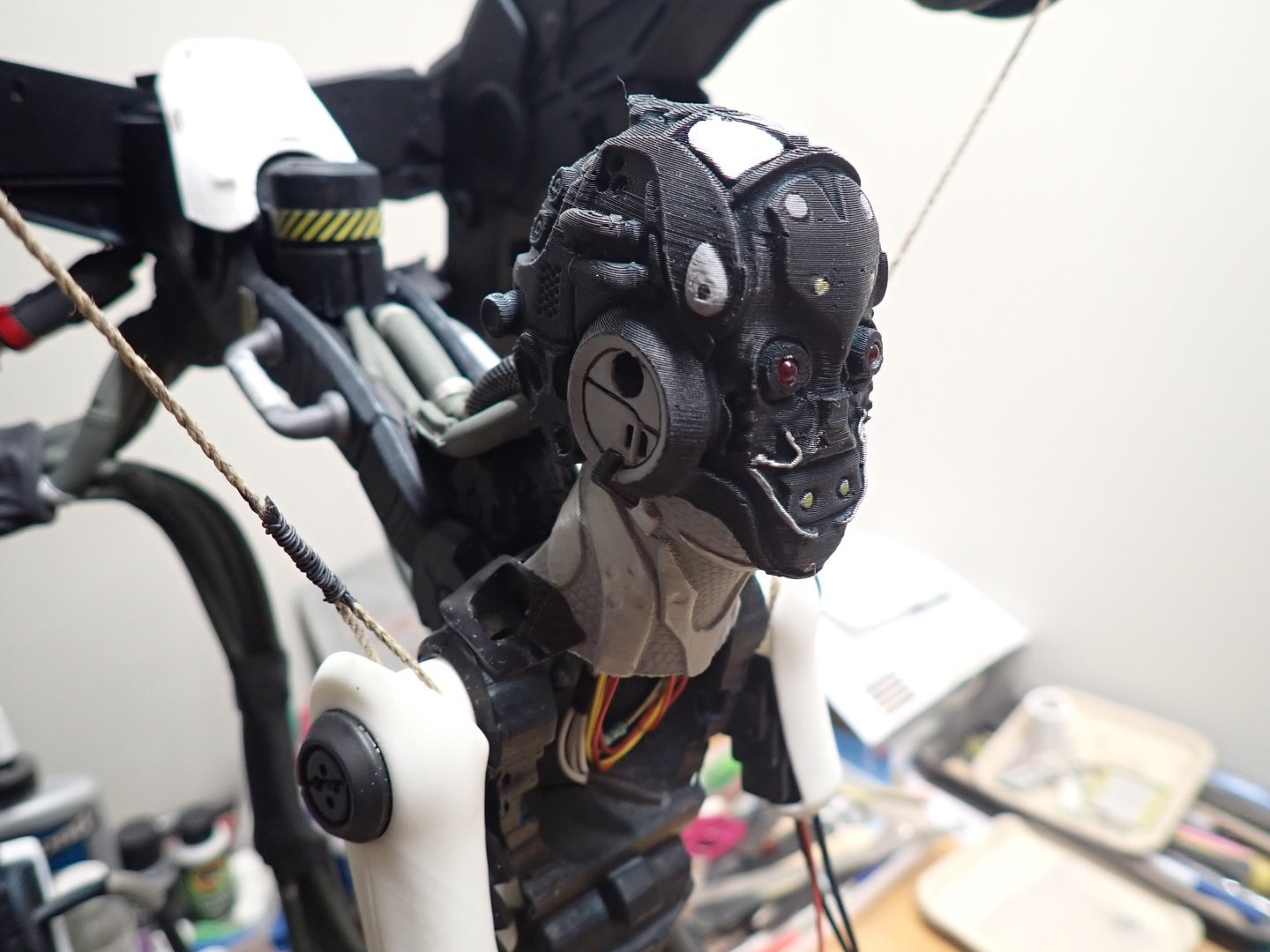
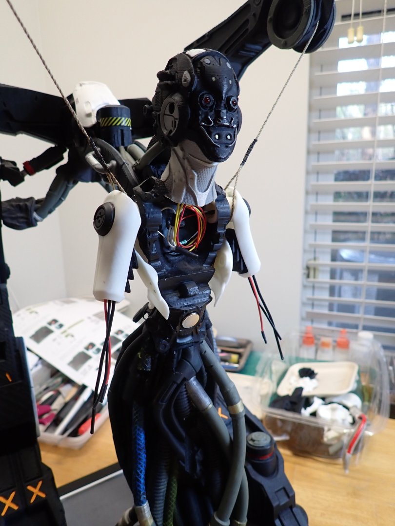
We are coming near the completion of this crazy project. In the meantime, here are a few pictures showing the progress centered around the head, mostly. Notice the ear rings with a fine titanium gold band, and the various wires and hoses used for cooling and data transfer. For the data transfer, I used what is called Multimeter cables in black. These cables are made of hundreds of very thin copper strands sheathed by a very soft and flowing insulator around them. They are perfect, as they flow naturally. For the cooling, I used small neoprene tubing that I had from my last visit to the O2 bar in Breckenridge, CO. I tried to fill it up with an orange concoction, but capillarity is playing against me. Overall view of the creature: The face is installed, after a very crude make-up session: More elements of the armor are added: Pelvic and chest plates. I need to correct the lines on the side of her chin.... Below is a comparison between 100% size filament printing and the 89% resin printing: Filament printing does not even come close in quality and finishing, at least on my old Ender 3 printer. The final picture for this update, shows all the mishaps that took place in term of printing, both filament and resin. It is a mixed bag of incorrect size, non-correctly-supported prints, filaments separating,,,and unused parts. I still have to work on the neck armor plate and the computer screen located on the side of the hangar. Stay tuned.... Yves


-
I am with you regarding the blotches/patches on the fuselage, on these German planes. I had the same issue when putting together that VTOL Focke Wulf. Like you, I used a cut brush. Not ideal, for sure. Yves
-
It is simply amazing that paper models can be so realistic and detailed. Truly, this is Alchemy done in South Carolina. Yves
- 90 replies
-
- 10
-
-
Bellisima !! In 1/96th scale, your work is pure marvel. Yves
-
Serikoff, Your build log is an incredible Tutorial. I admire your work and the precision and cleanness of it. Yves
-
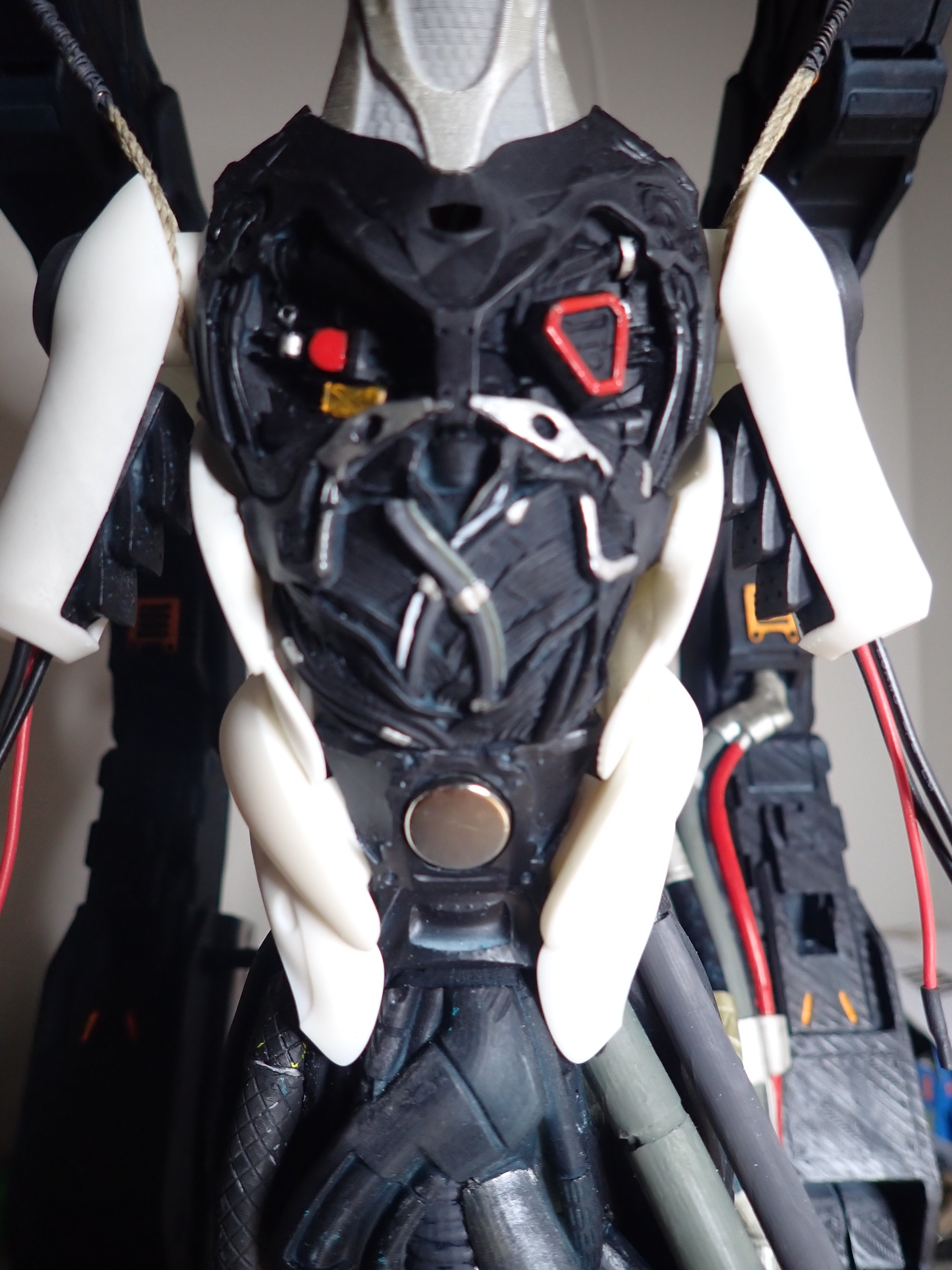
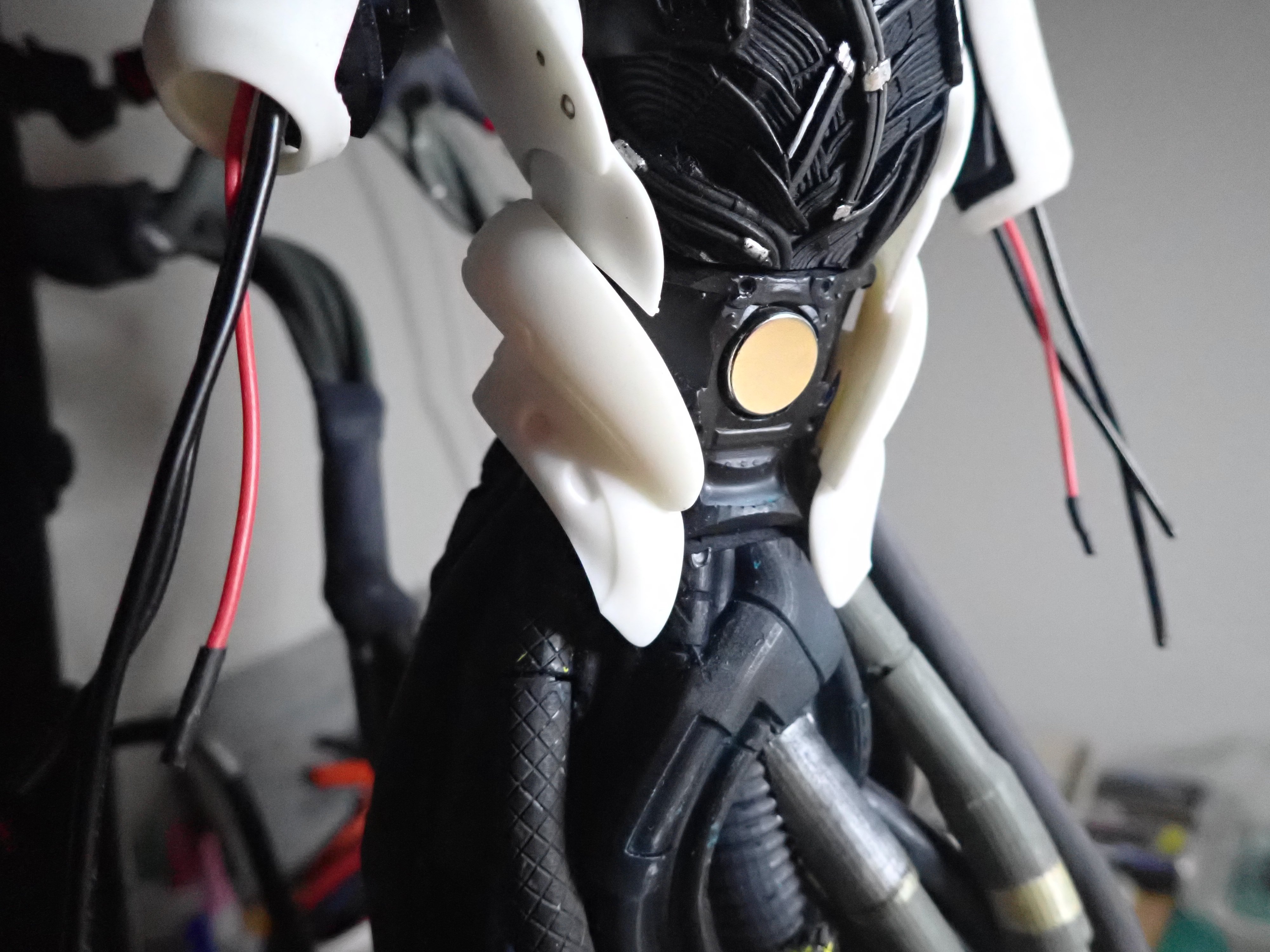
Hips armors and chest are installed. The chest can still be removed but it is very tight and does not need to be glued: The hips armor plates are also helping with a tight fit of the chest plate. In the center, you can see the magnet that is used to hold the pelvic armor plate (above). Overall view of the creature as it stands today. Once all the armor plates have been installed, it looks a lot more sympathetic than it does at the moment. Yves


-
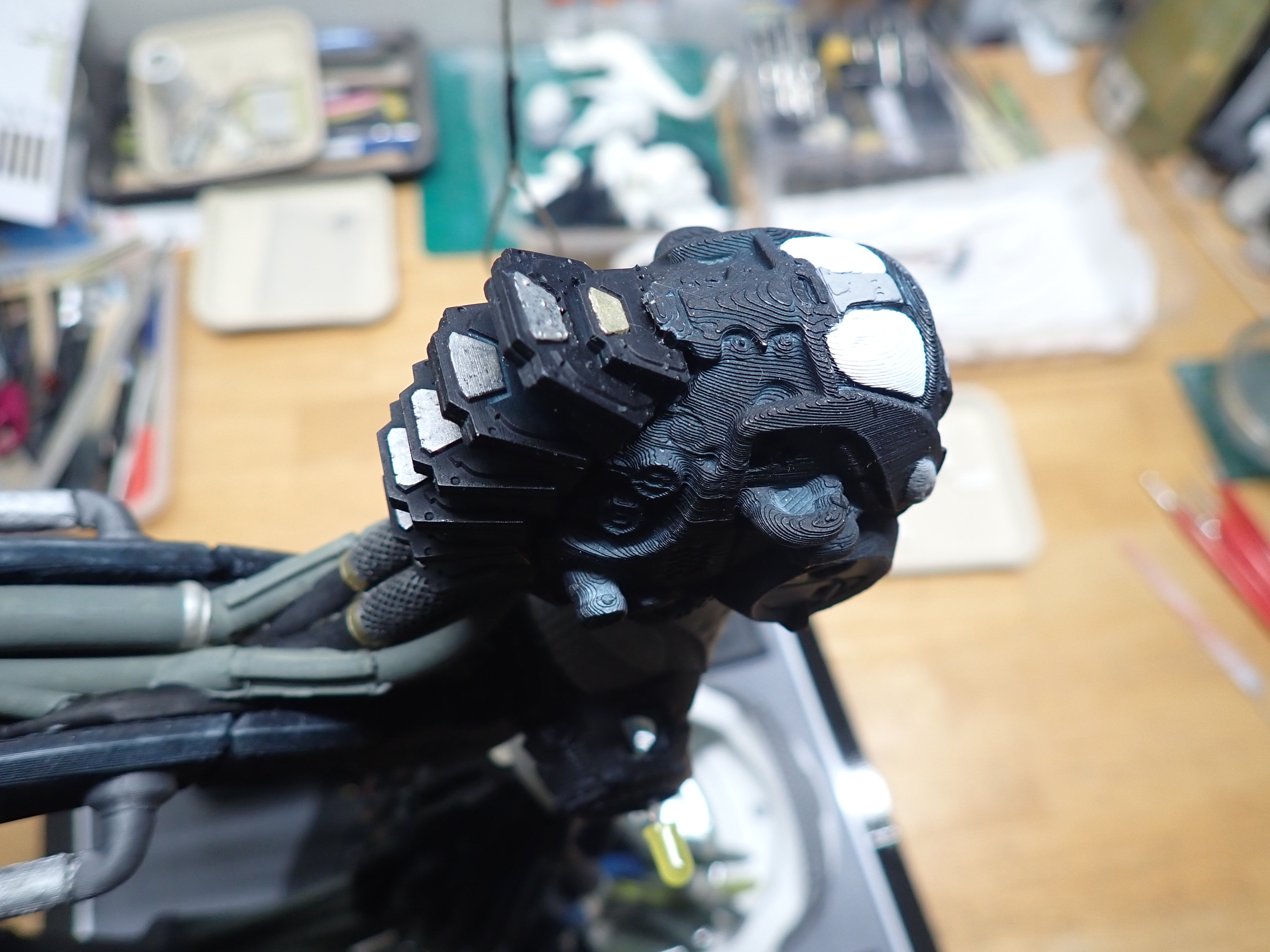
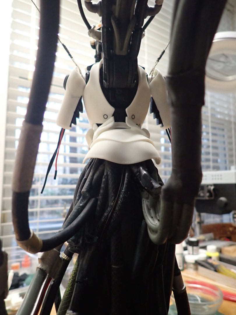
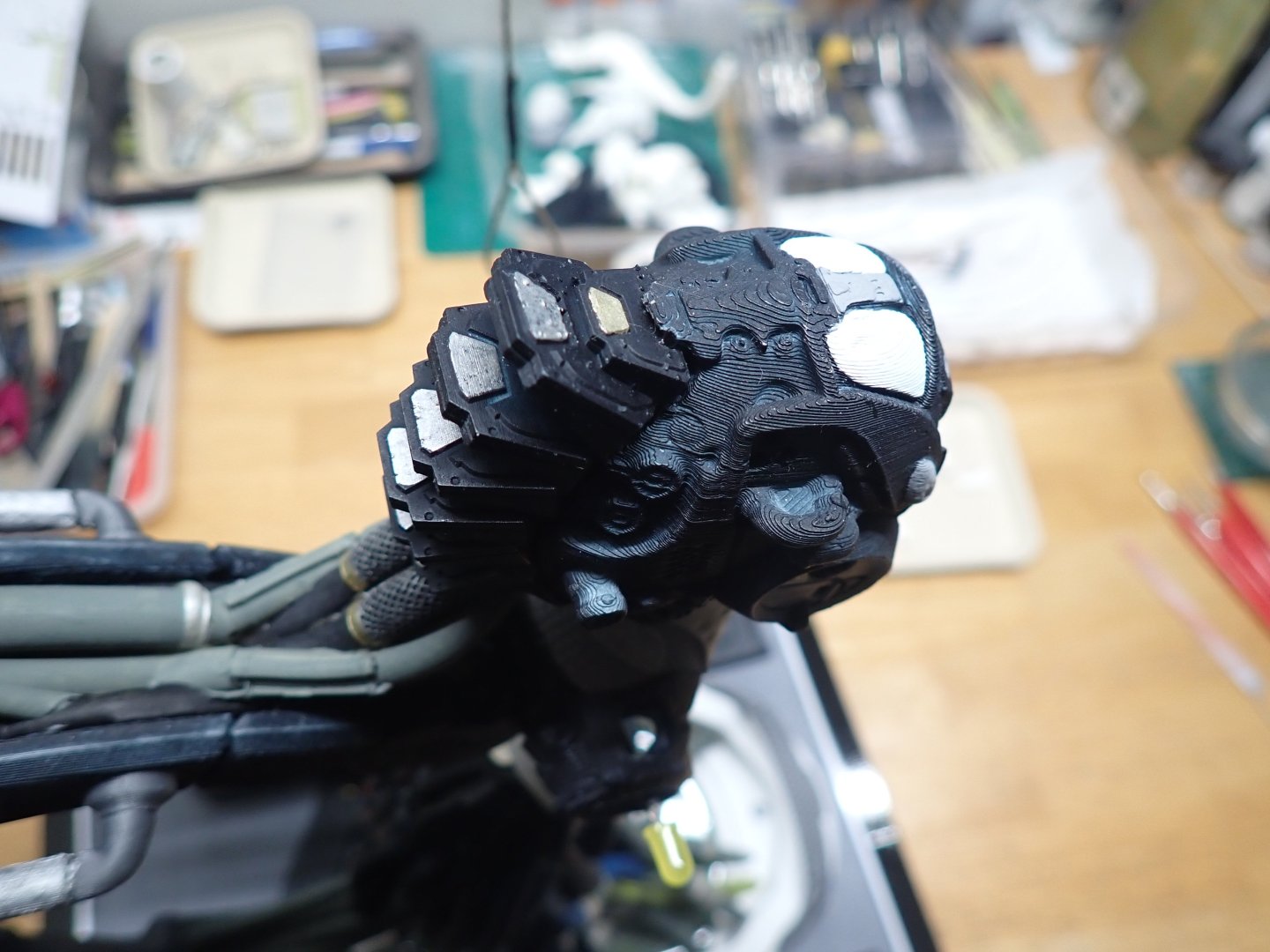
I am now spending some time on the AI creature, starting with her Mohawk, on the back of her head: I suppose this Mohawk is a massive radiator for the computer and chips installed in her cranium. Then, I move to the rear sides of her armor: These are glued in place, using the chest to position them exactly. Most of the armor plates are removable and secured by magnets, but not these two pieces that need to be perfectly installed and glued so that all other parts of the armor can fit. To do that task, I removed the shoulders and you can see the Orange LEDs protruding out, on each side. Once glued, a few pictures: And with her little skirt in place (held by magnets): Yves


-
Absolutely amazing. I love the precision of your work, color of the wood and the way you approach the various tasks. Such perfection. Yves
-
Incredible and beautiful work. I like the 3D printing approach for the frames. Quite unusual and smart. Yves
-
Mike, yes, it is most definitely a very difficult kit to print and put together. Thank you for the compliments. Yves
-
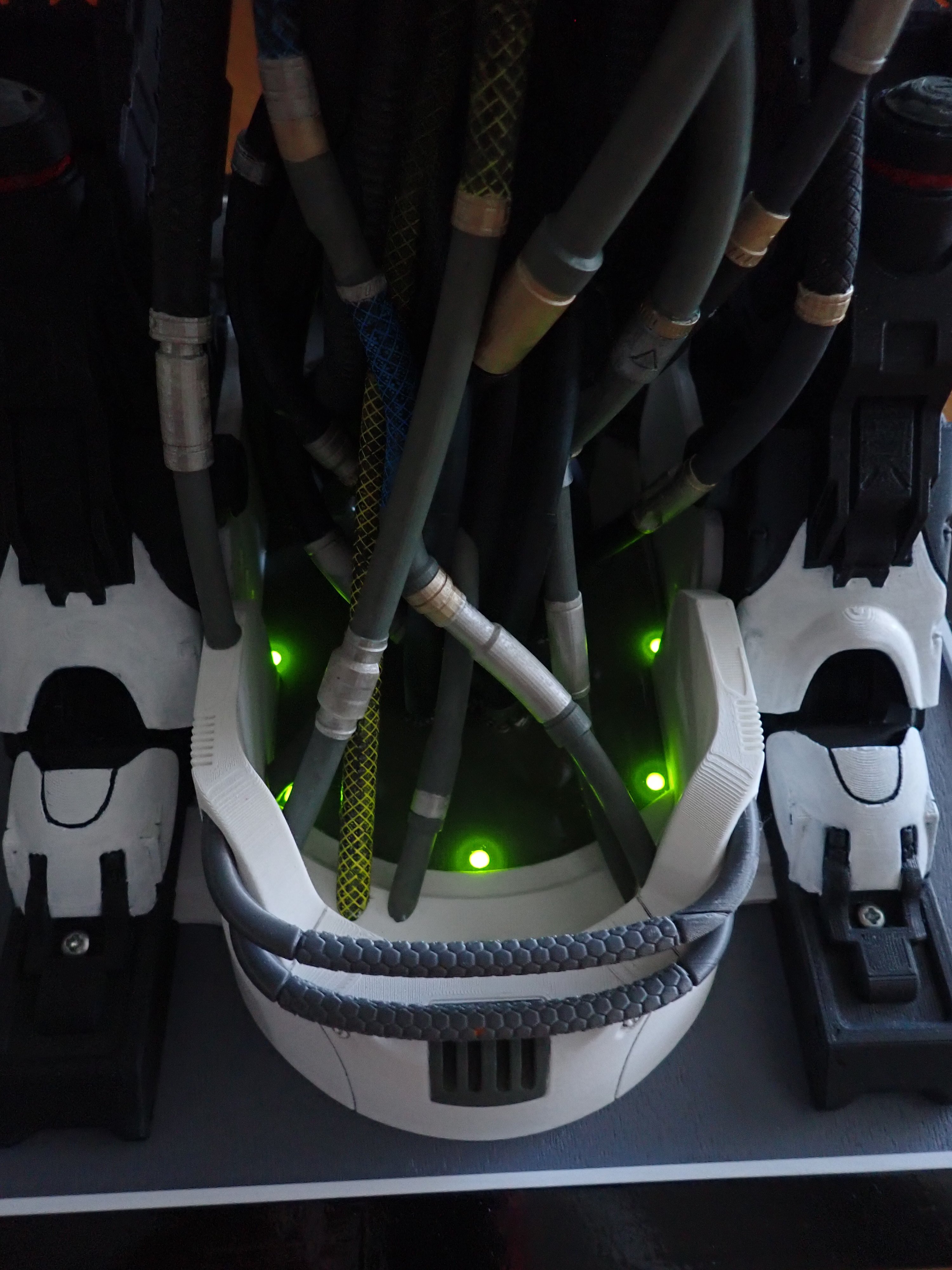
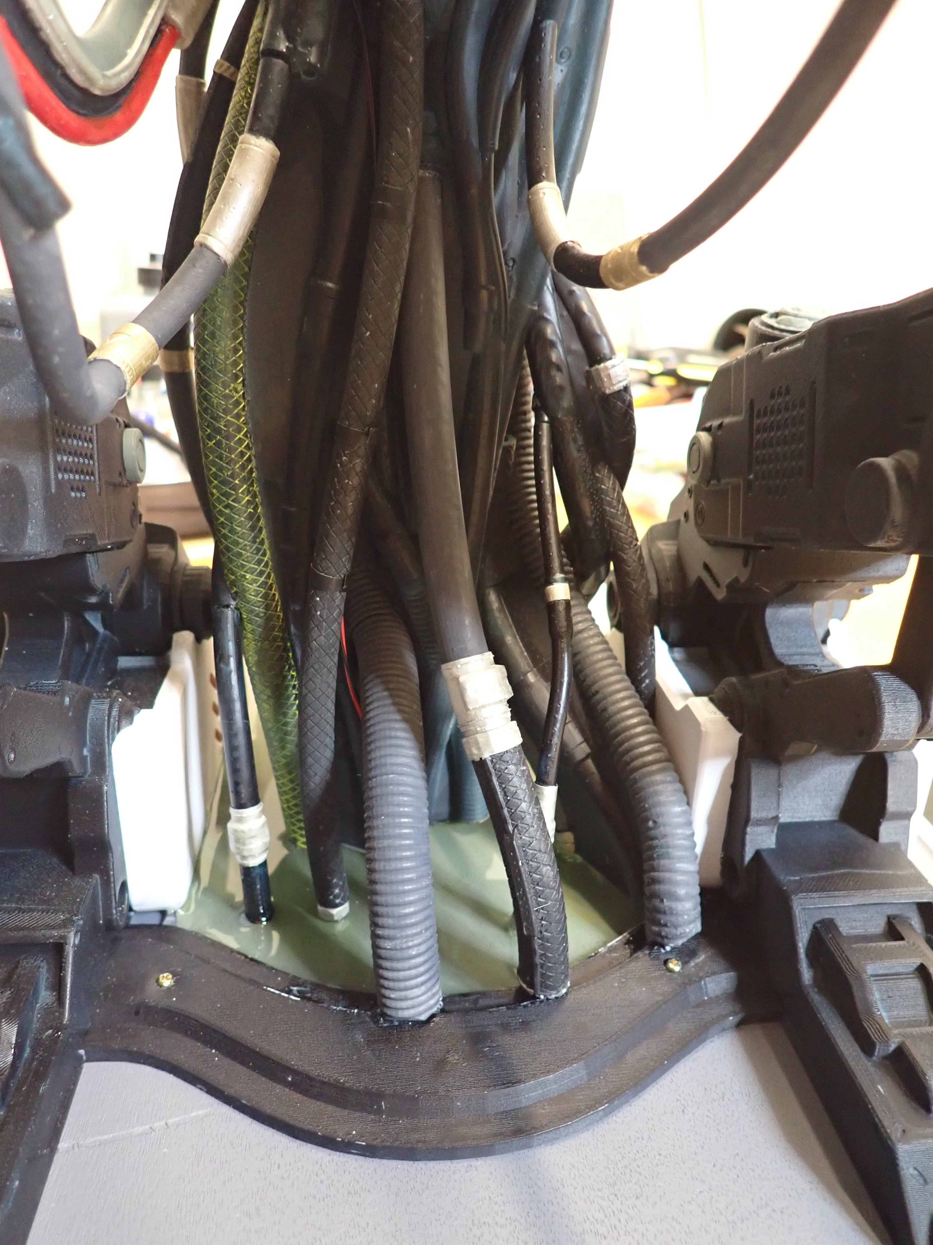
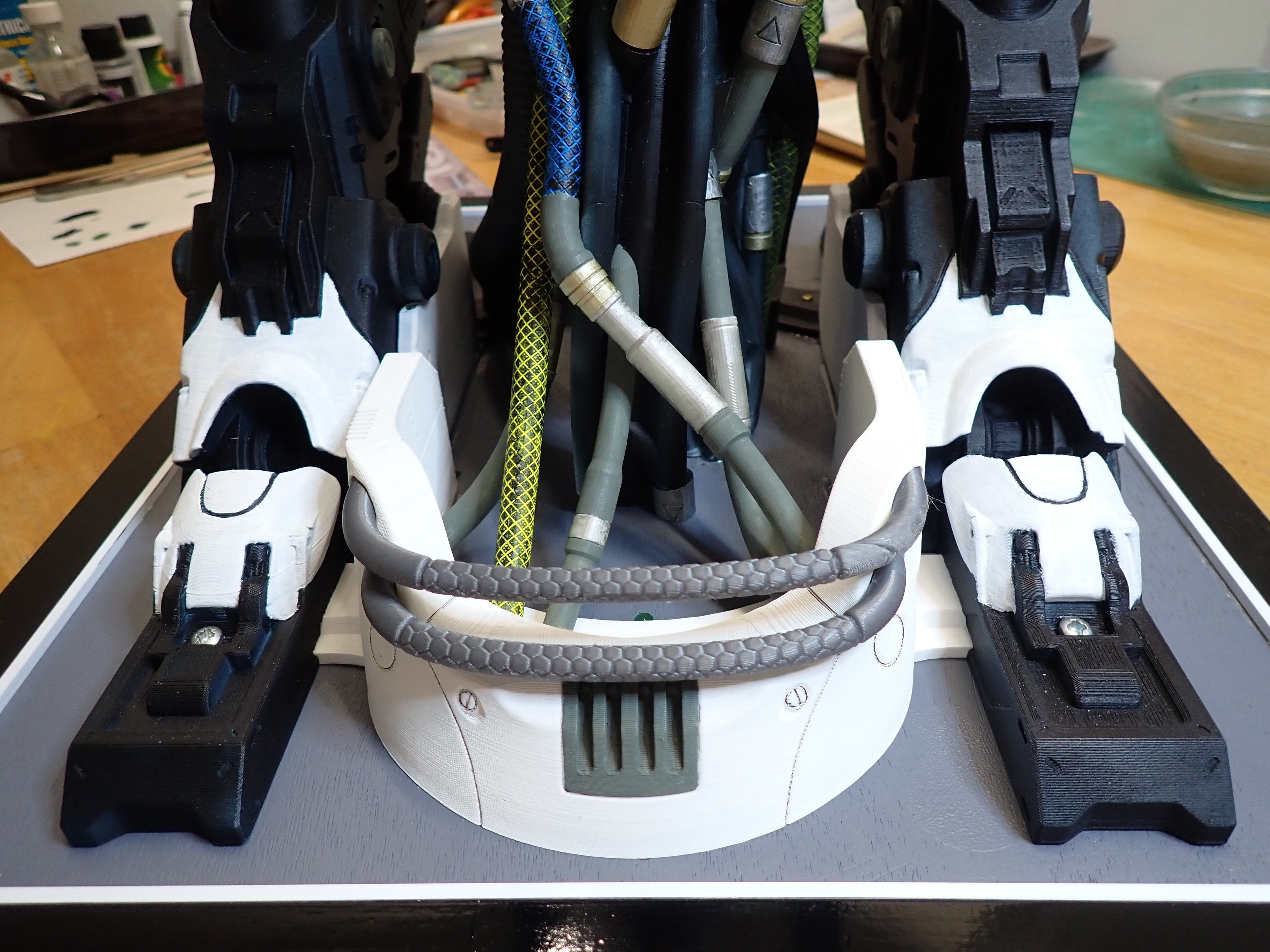
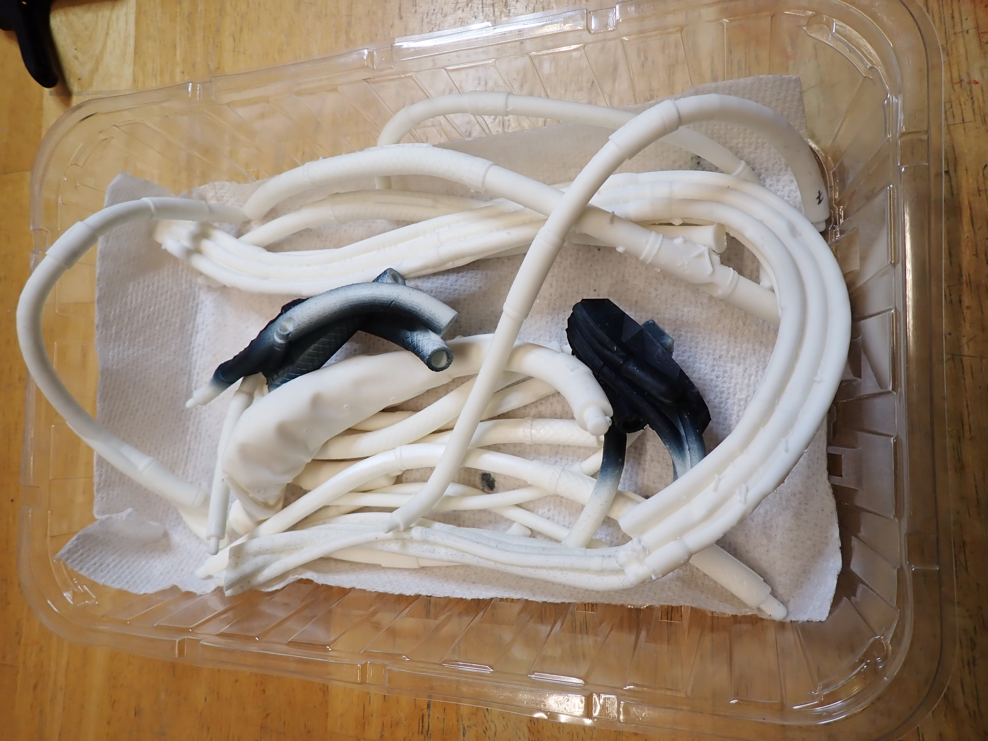
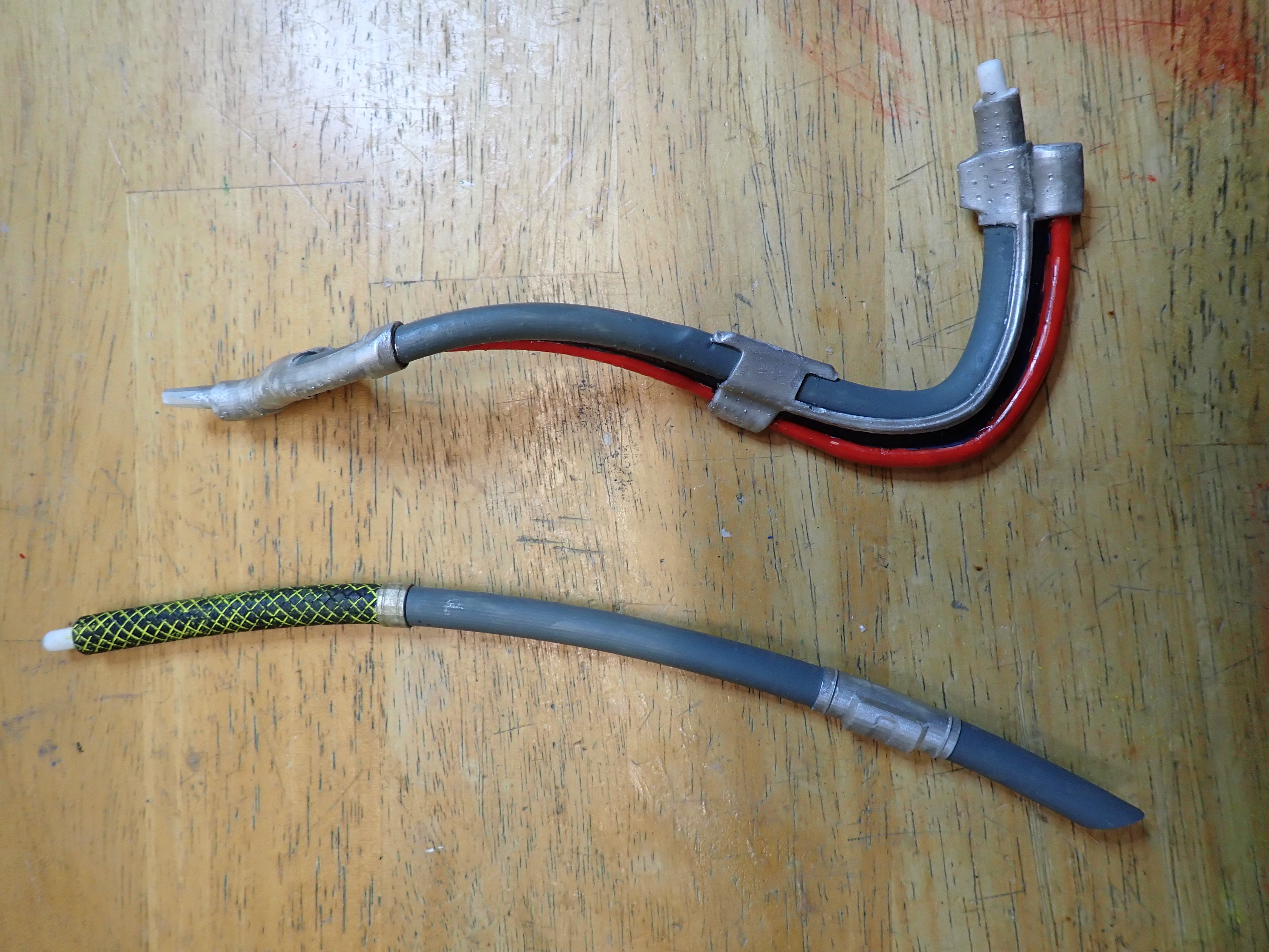
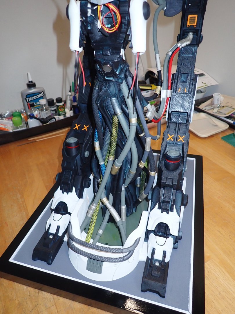
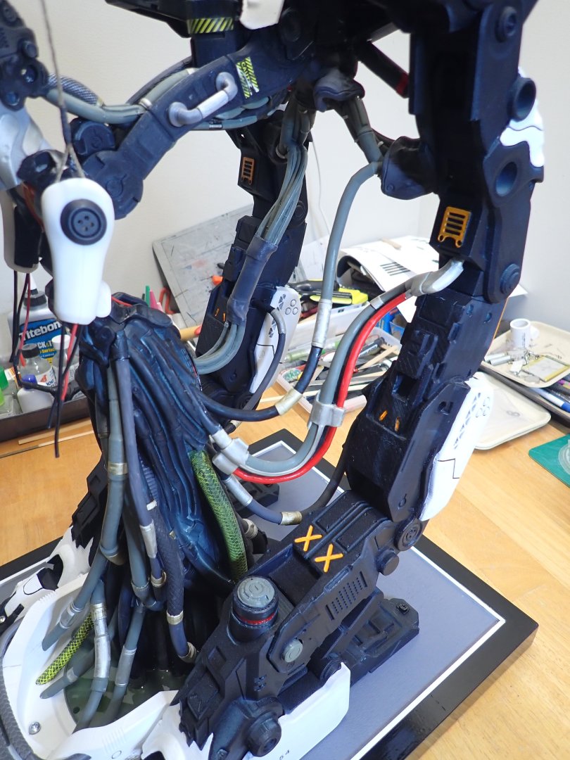
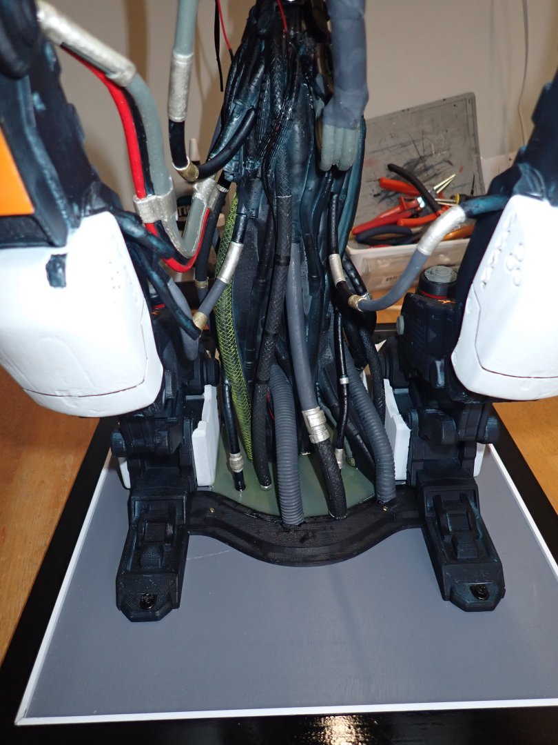
I am almost done with the plumbing. It has been quite a rocky path, to find the location of all these hoses and pipes. In addition, the connection between the Robe of the AI creature and the Hangar is made difficult, because of the two different types of printing techniques: Filament for the Hangar and resin for the piping. Inevitably, there are some slight differences in sizes that makes the connections delicate or impossible in some cases. Anyway, some pictures: I am quite happy with the "pool" of resin on the base, as it makes everything so much sturdier. One section that really was impossible to connect is this one: The resin pipes are absolutely inflexible and the anchoring points did not match. I decided to cut the pipes and create some kind of bag in the middle for their connection. I may change that in the future as I am not too happy with the way it looks. Most people and rare implementation of that kit that you may find on the Internet, are going with a fully dystopian approach and lots of weathering. I really suck at weathering and decided to not go that route. I wish I could have done it, as it makes the model so much more dramatic. I have a few hoses left and truly could not find a location for them: I may be able to place one or two more, by cutting and reworking them..... we will see. Now, is the time to work on the details of the head and torso of the creature: Yves


-
Great printing results Craig. It will be interesting to see how this new paint is doing on resin, which is never an easy medium to work with (glue, dust, brittle....). Yves
-
What a gorgeous boat. You did a fantastic work with it, worth displaying in a museum. Yves
-
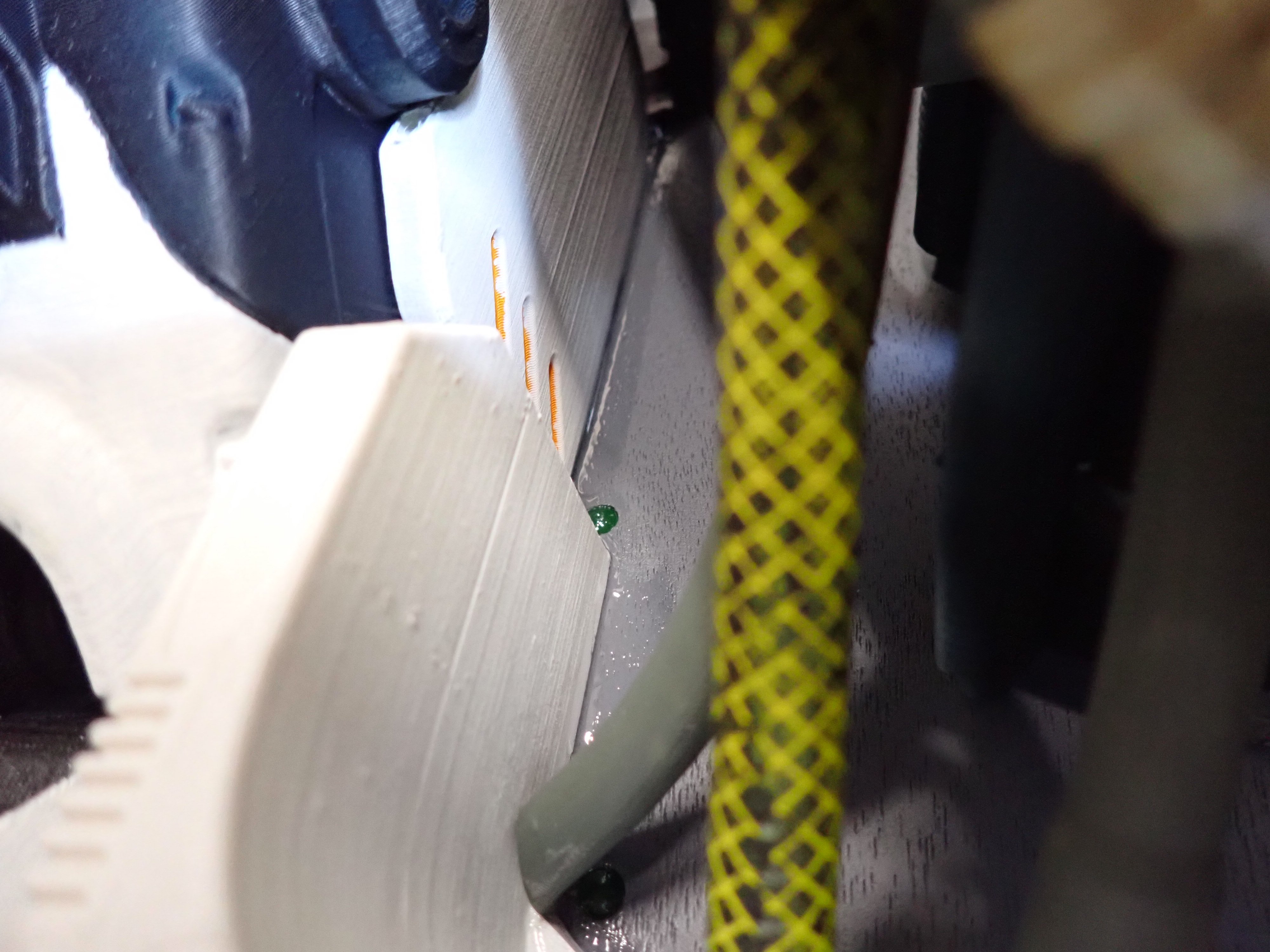
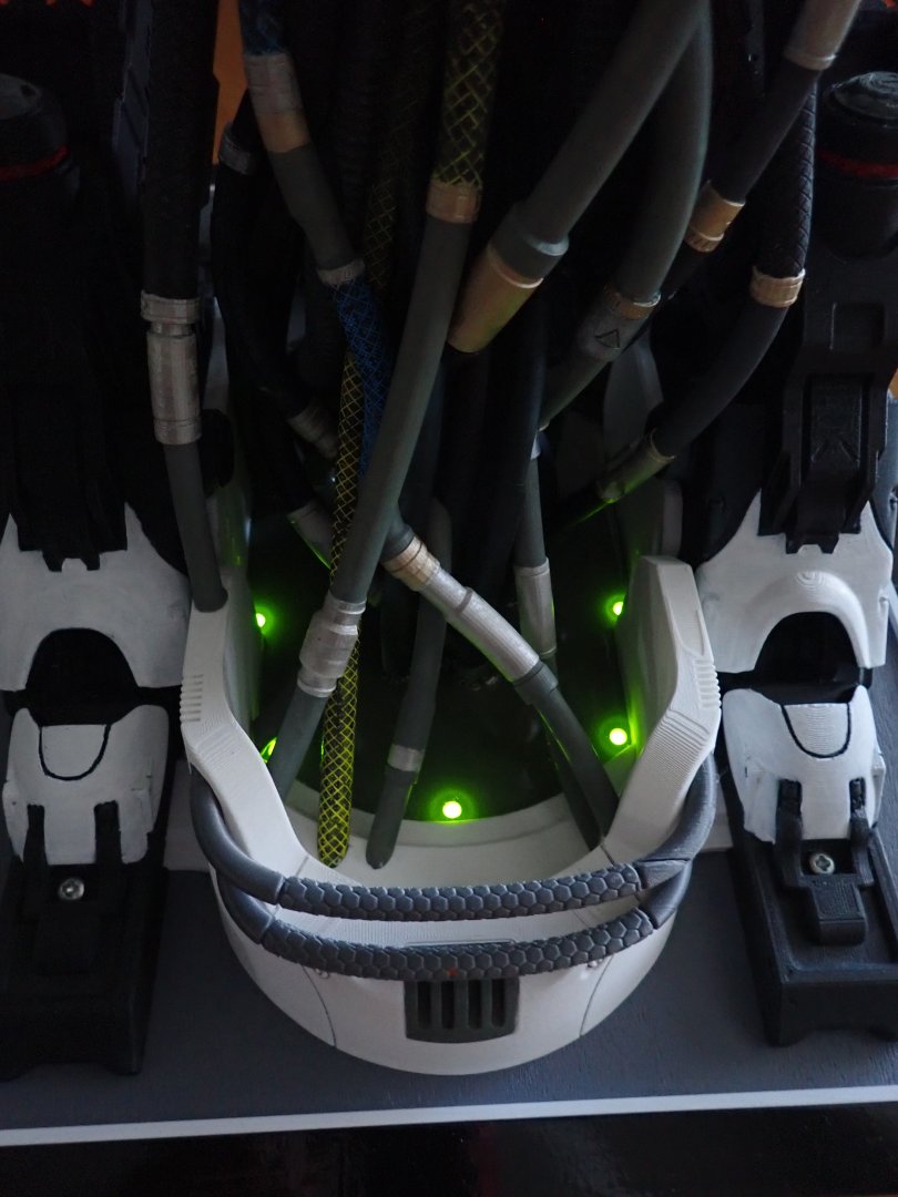
I managed to install another half a dozen of pipes. Making slow progress using length, size, appearance and connector diameters. It is not easy and the existing pictures of the original design are helping a lot. I also poured some acrylic resin with a couple of drops of green dye. I do not want to pour too much as it may leak between the main feet of the Hangar. The benefit of that resin is also to secure all the pipes and hoses to the base. No more wiggling. Below are close-ups on a few new hoses that I installed: I still have another 12 to 15 to place between the creature/robe and the various components of the hangar. Yves


-
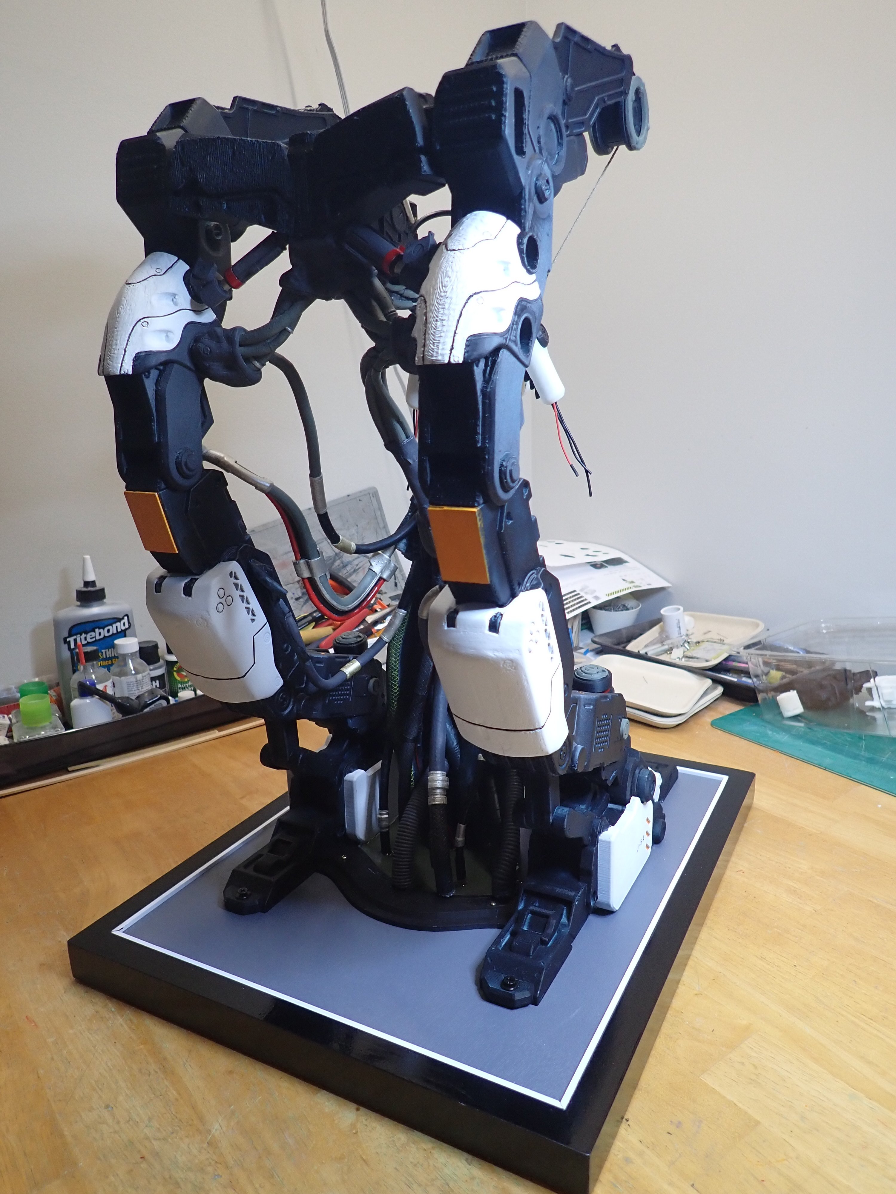
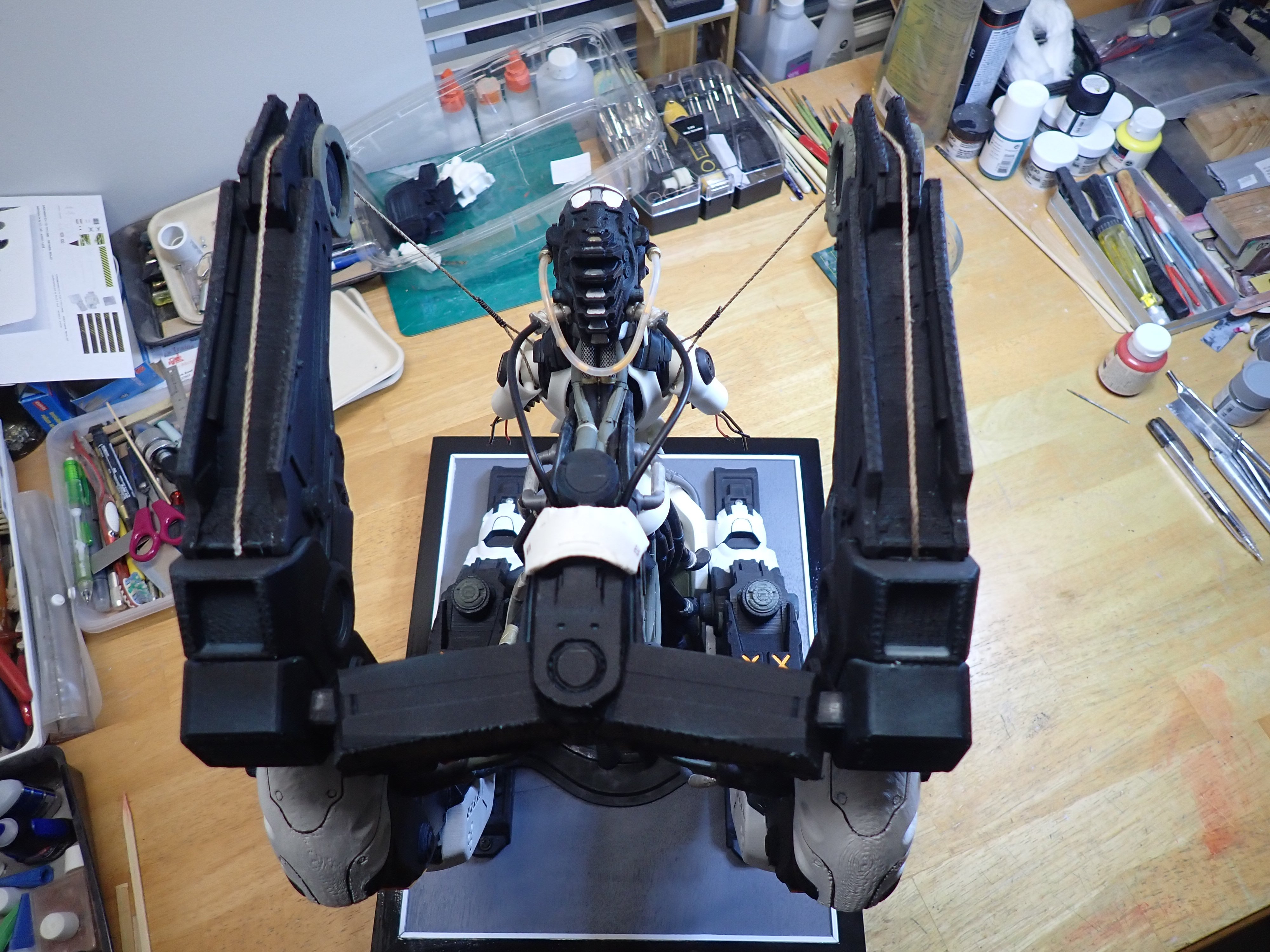
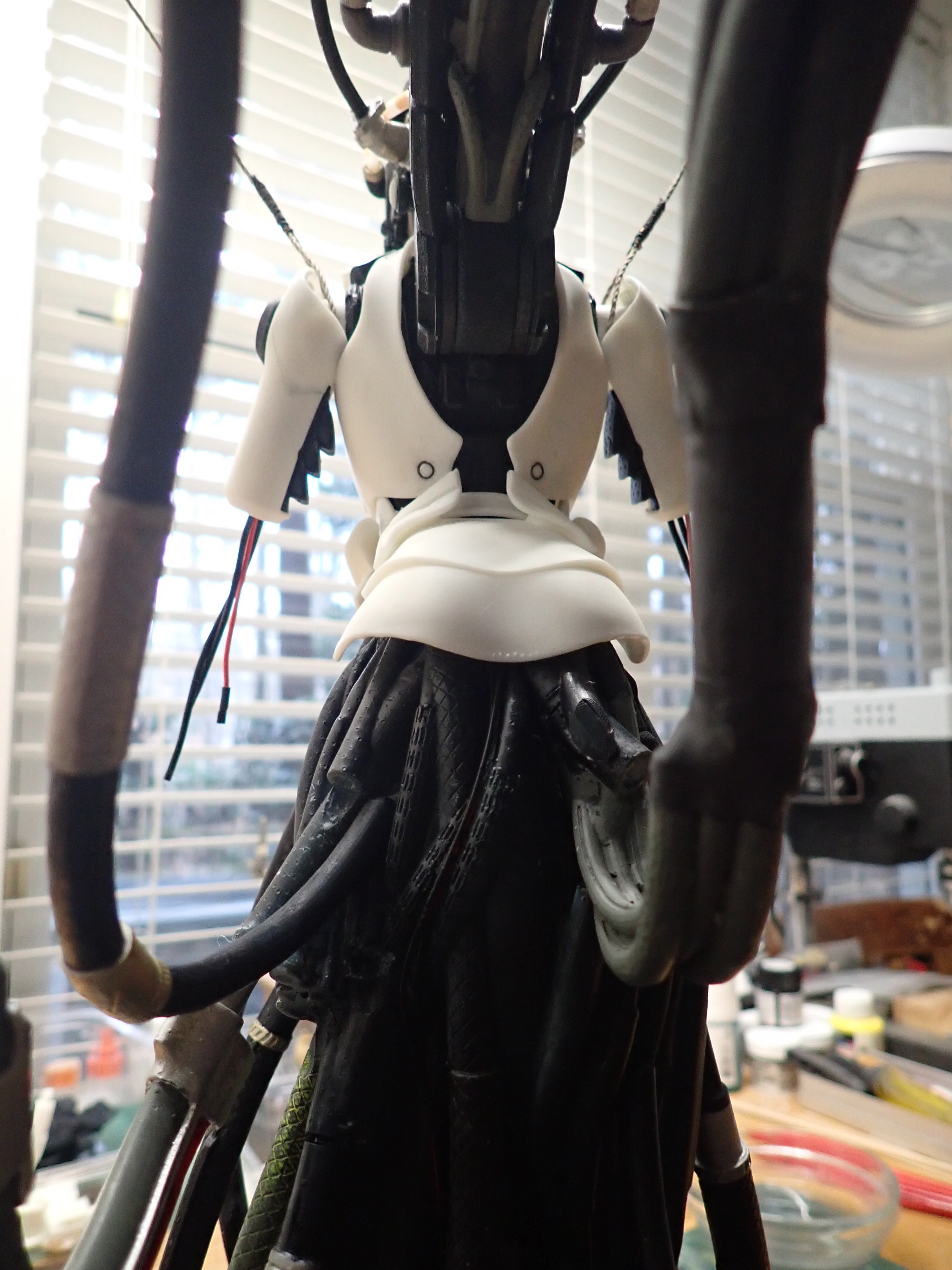
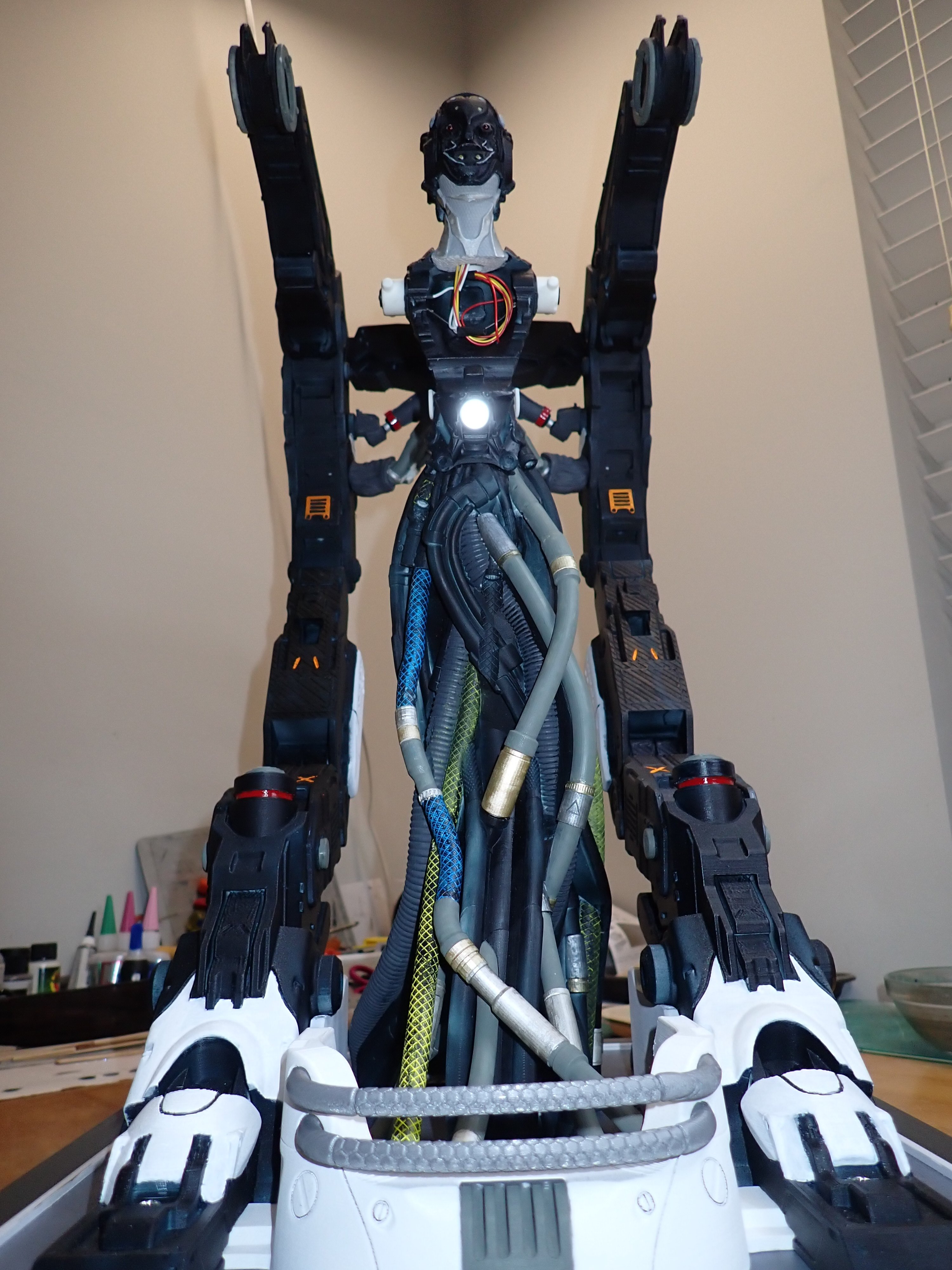
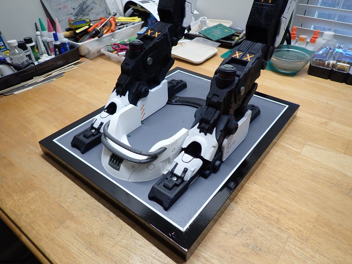
Major milestone achieved, yesterday: the permanent gluing of the "robe" on the wooden base: Before this step, I placed some transparent caulking all around the intended pool that will be used to secure and terminate all the pipes and hoses: Hopefully, the caulking will prevent the acrylic resin from leaking. As we all know, the resin by capillarity will find any way out of where it is supposed to stay and polymerize. A few pipes and hoses have been painted and installed: The back and neck are now connected to the "Hangar": The two cables suspending the creature under the arm pits have been installed: I still have a ton of hoses and tubes to integrate. It is not easy..... The painted cables/hoses have been identified and I know where they locate: I hope you are enjoying this dystopian diorama. Yves


-
Quite a change from sunny and warmy Florida.... Yves