HOLIDAY DONATION DRIVE - SUPPORT MSW - DO YOUR PART TO KEEP THIS GREAT FORUM GOING! (Only 75 donations so far out of 49,000 members - C'mon guys!)
×


yvesvidal
-
Posts
3,607 -
Joined
-
Last visited
Content Type
Profiles
Forums
Gallery
Events
Everything posted by yvesvidal
-
 Beautiful job overall. Lots of good idea in your thread. I will have to follow your Build Log when I decide to build that kit, sitting in my stash. Yves
- 38 replies
-
- 3
-

-

-
- 18th Century Longboat
- Model Shipways
- (and 1 more)
-
Yes, I am aware of that and agree completely. My brother owned a 403 Diesel, a couple of 504 Coupe(s) and is currently driving his 504 Convertible (4 Cyl. not the horrible v6 PRV engine) among other cars. Modern Peugeot cars do not have the same quality and present absolutely no interest. Yves
-
In addition to that strange armored vehicle, Peugeot created something much more useful, the Pepper Grinder: Yves
- 39 replies
-
- 10
-
-

-
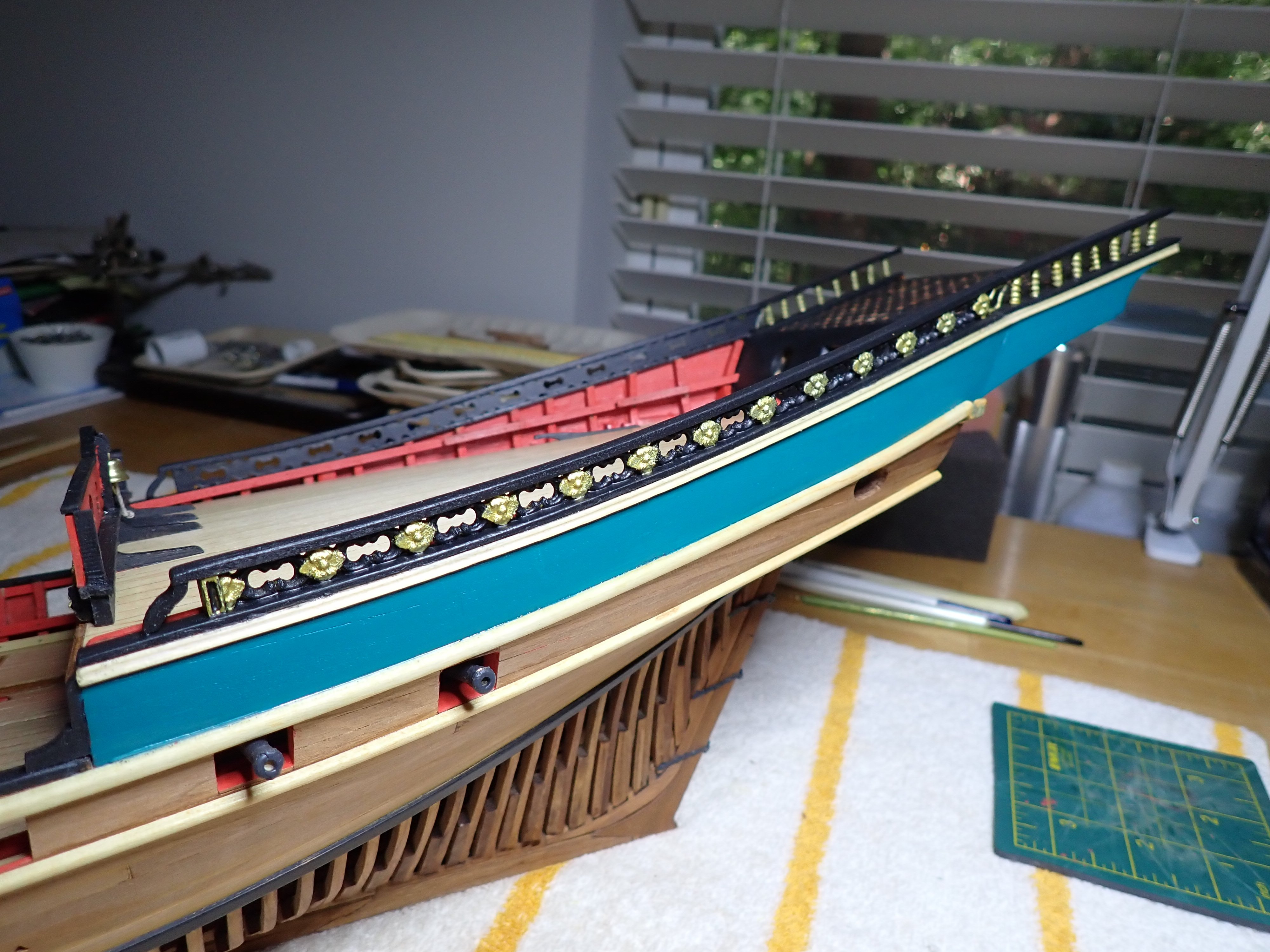
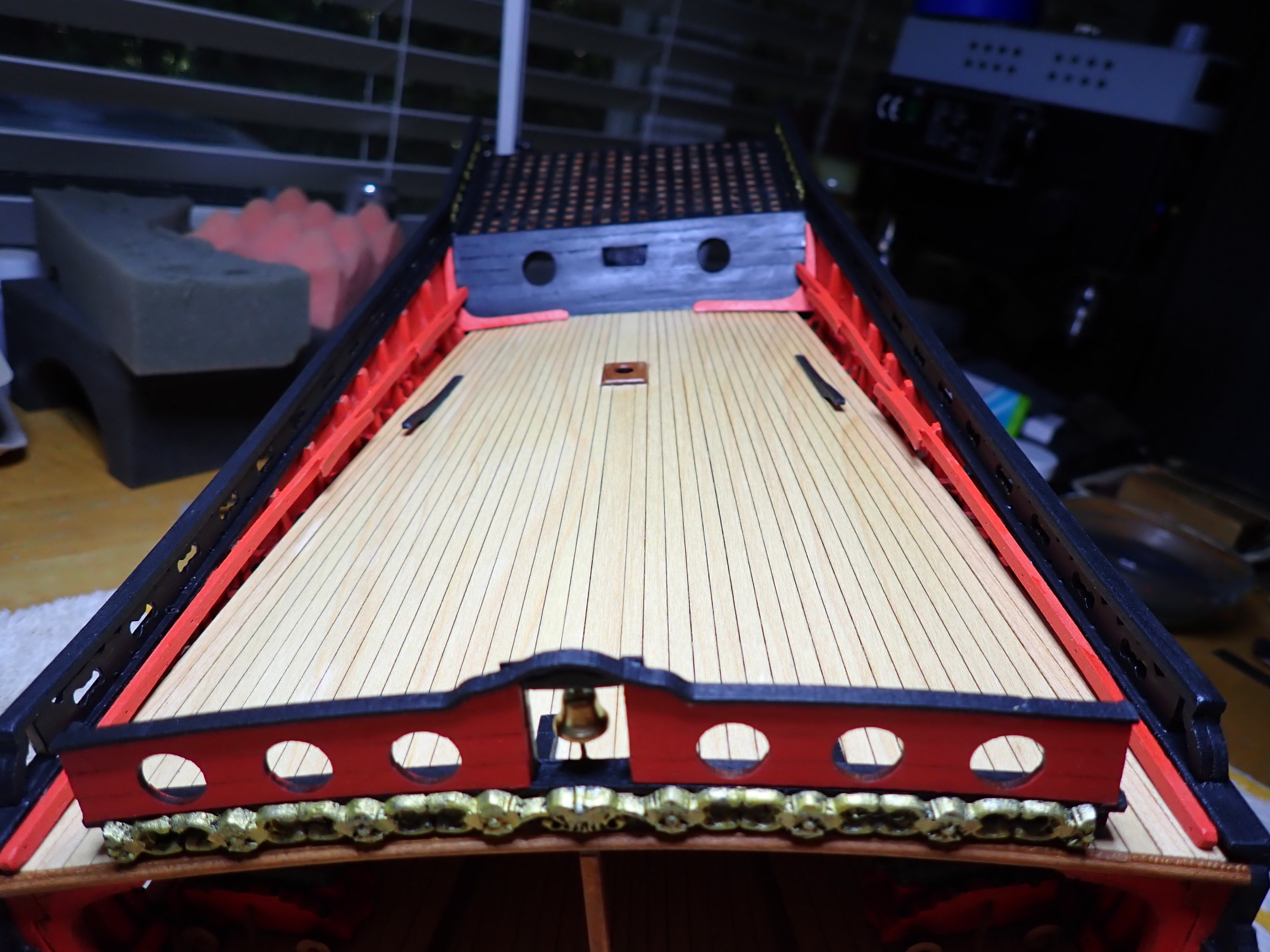
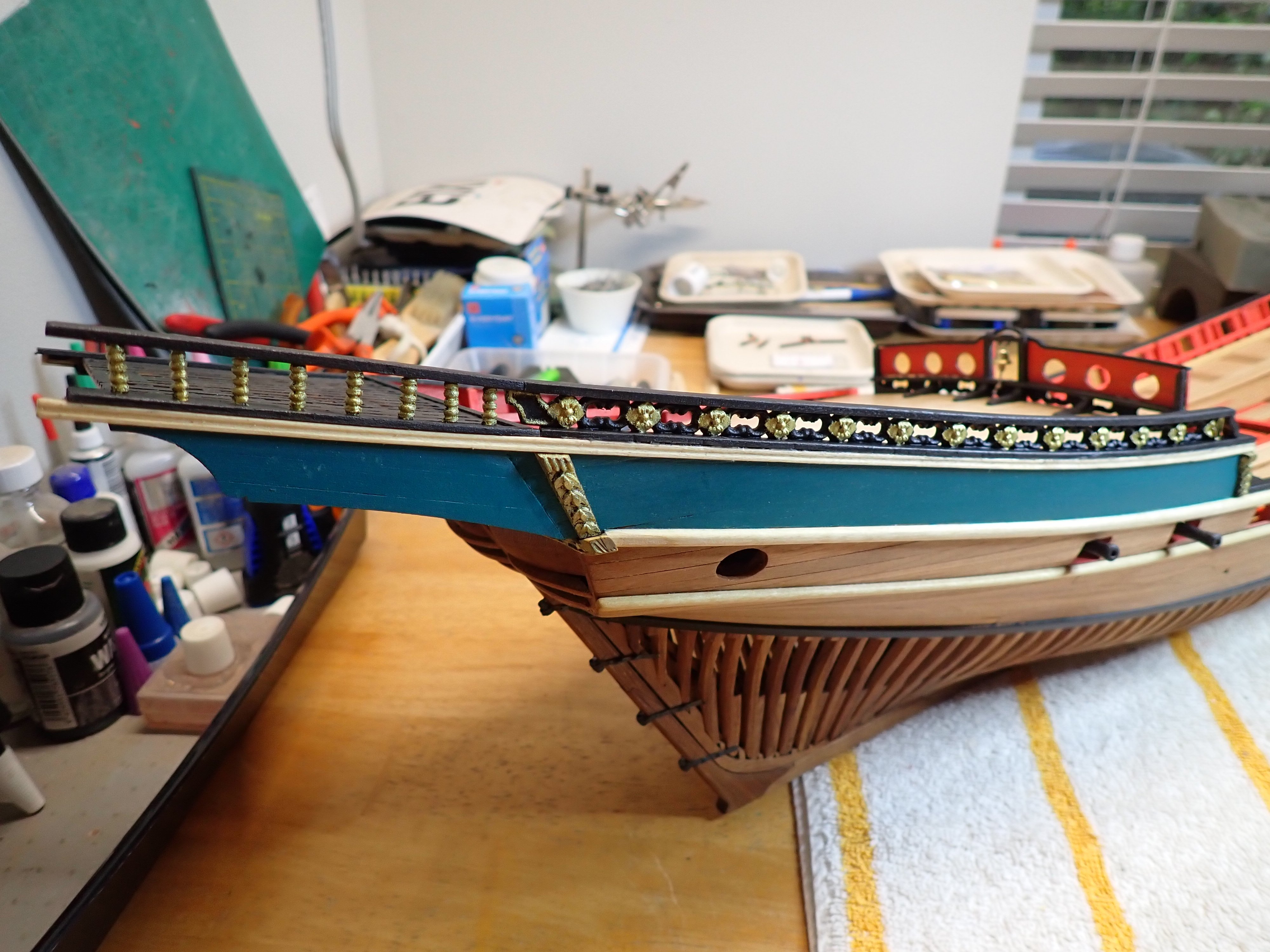
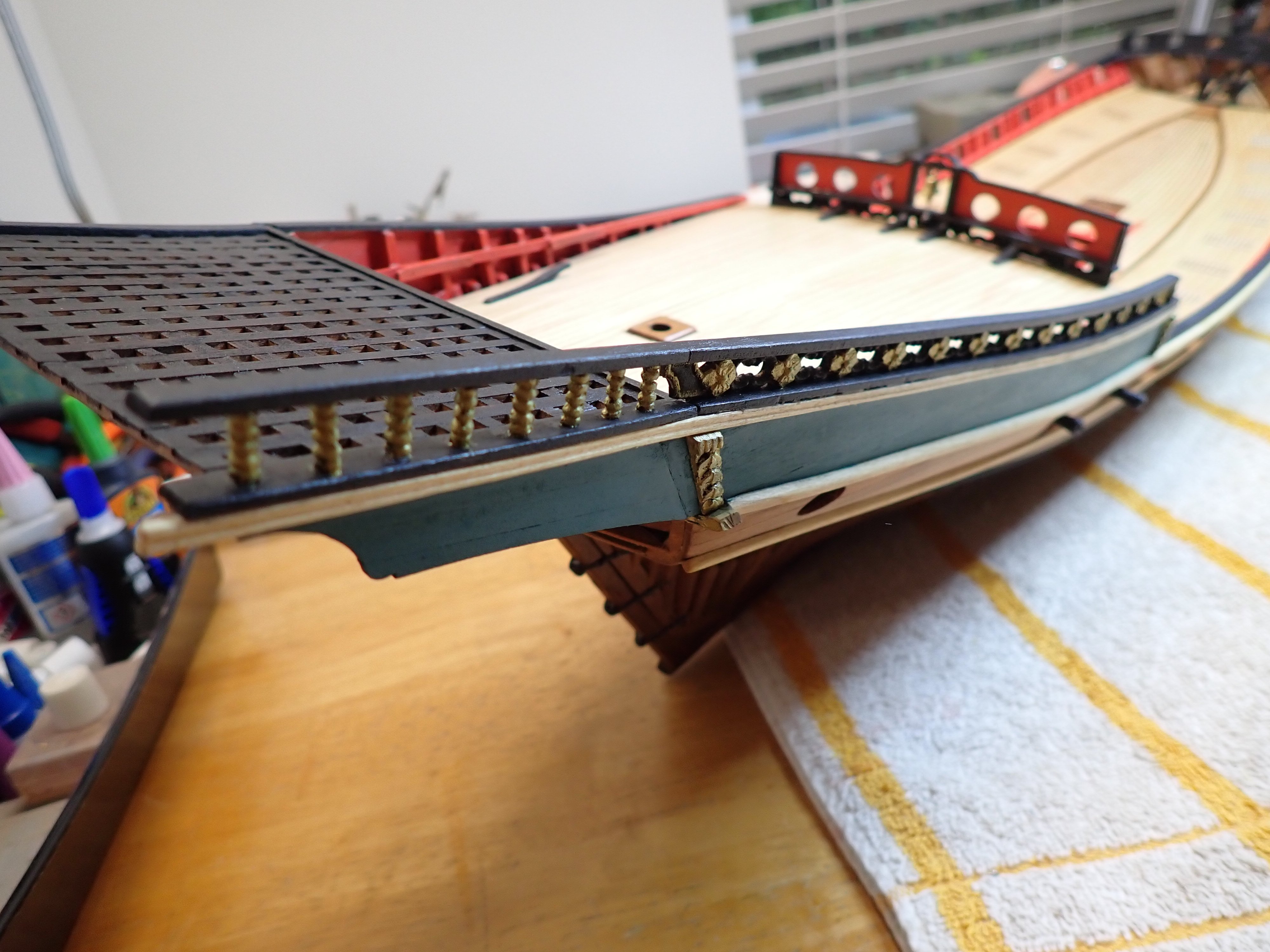
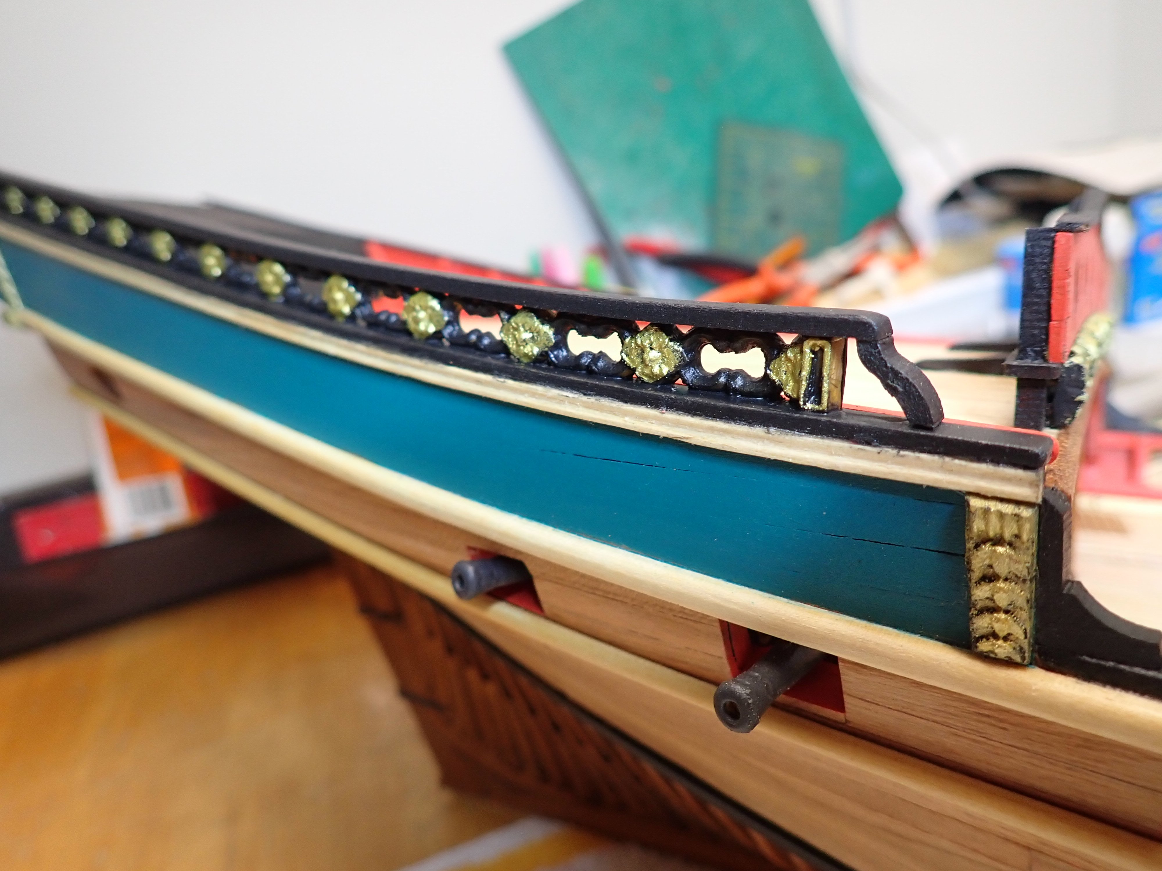
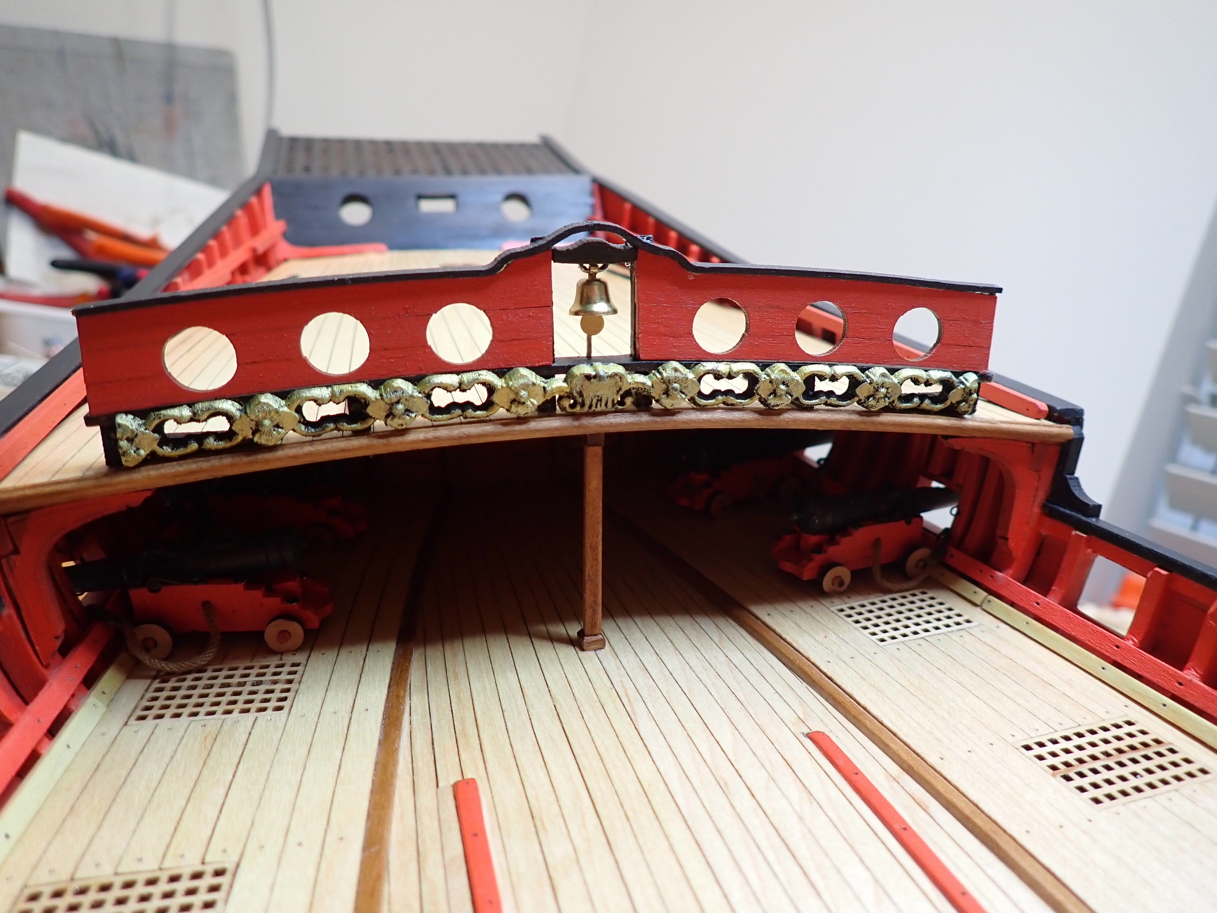
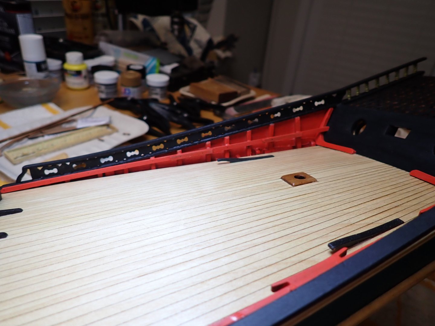
Now is the time to work on the railing of the rear quarter deck: The boxwood carvings are glued with liquid CA. And then, some painting is done: Now, I have to redo the same on the port side.... Yves


- 185 replies
-
- 14
-

-
-
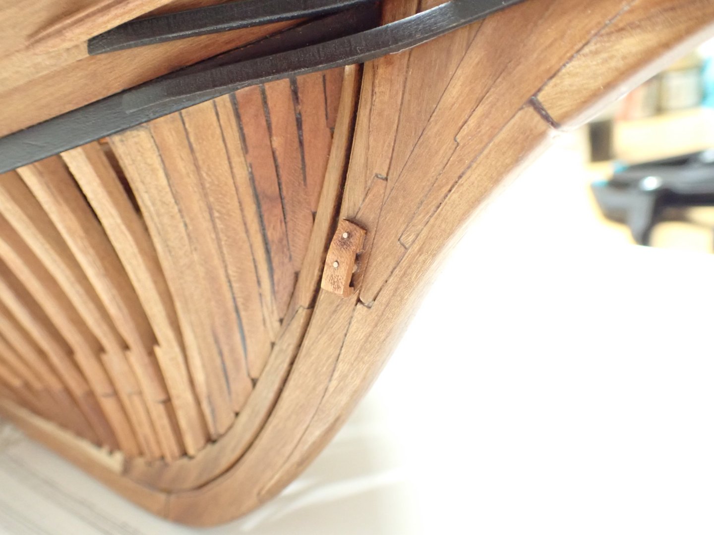
Very creative (and smart) way to represent the hinges on the rudder. It is definitely easier than using brass parts as I recently did it on my CAF Chebec. Yves
-
Such lovely and clean work. It is a pleasure to watch. Yves
-
It is hard to believe that this is 1/200 scale. It looks so realistic and perfect. Yves
- 202 replies
-
- 2
-
-
-
- Russo-Japanese War
- Mikasa
- (and 2 more)
-
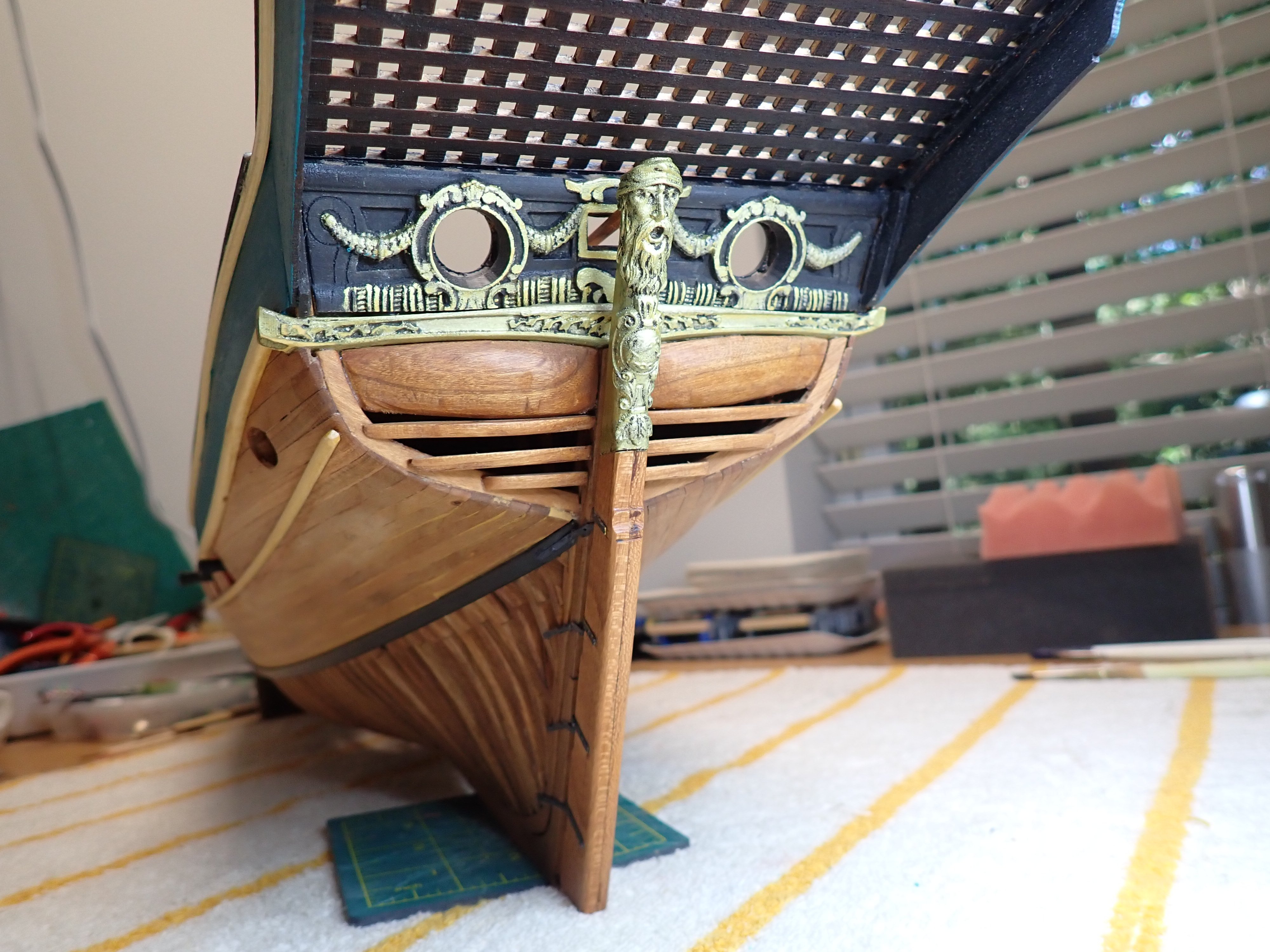
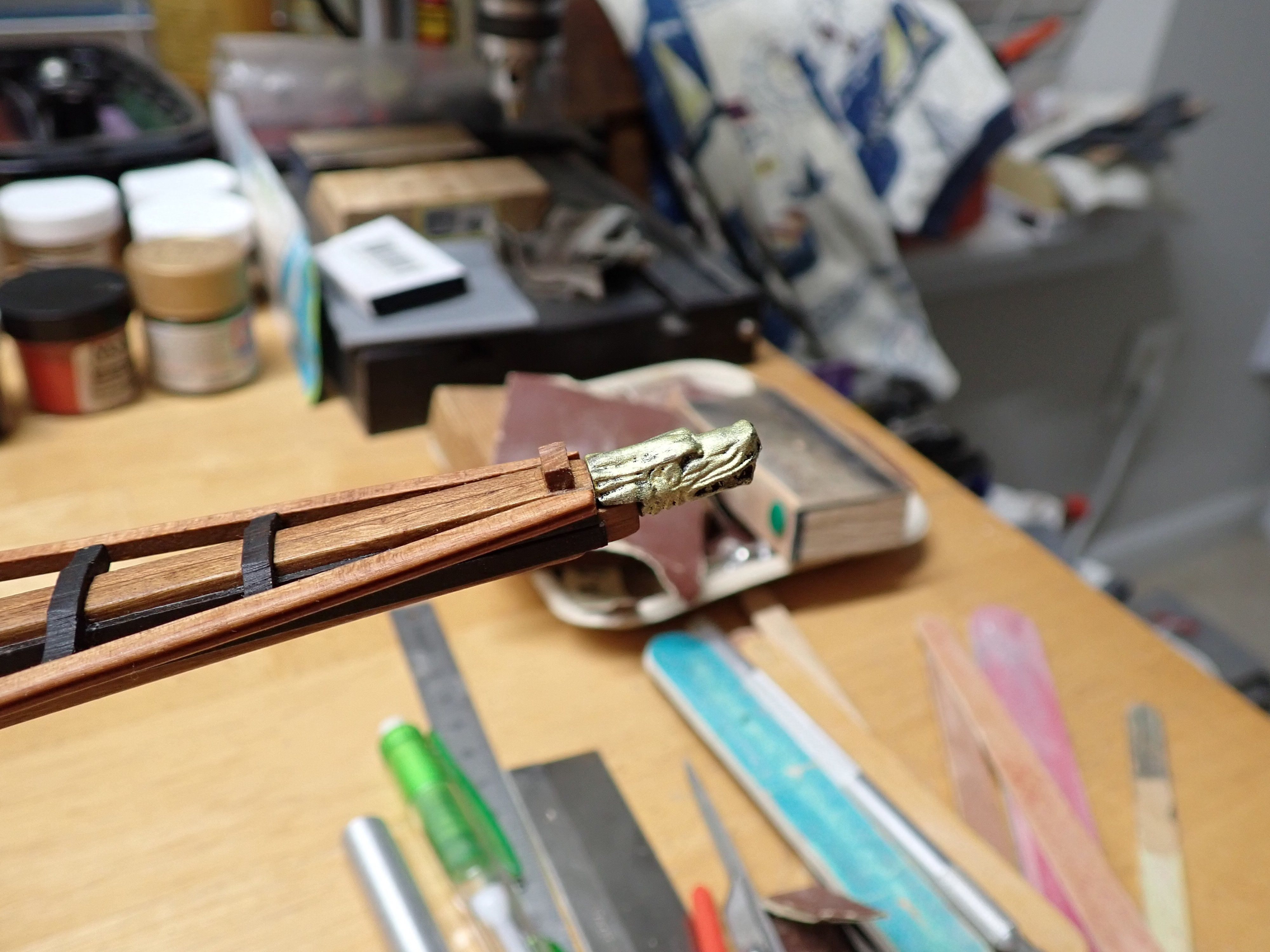
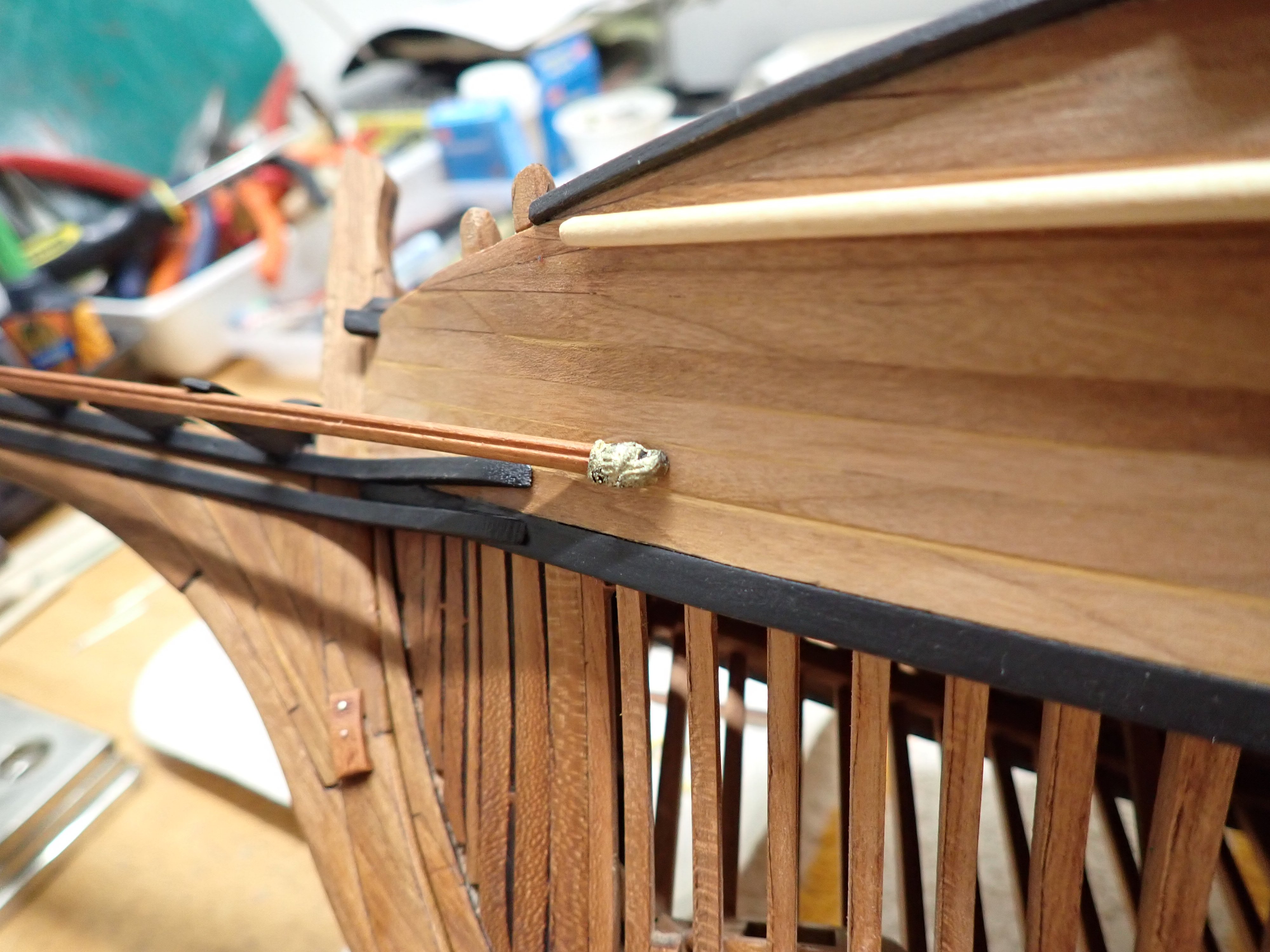
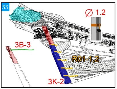
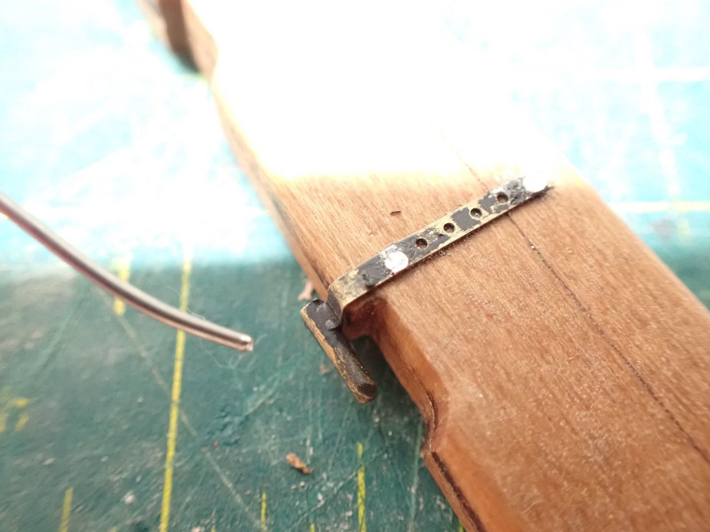
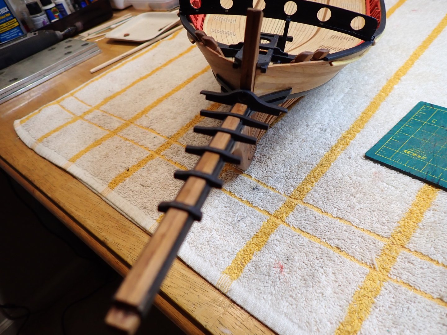
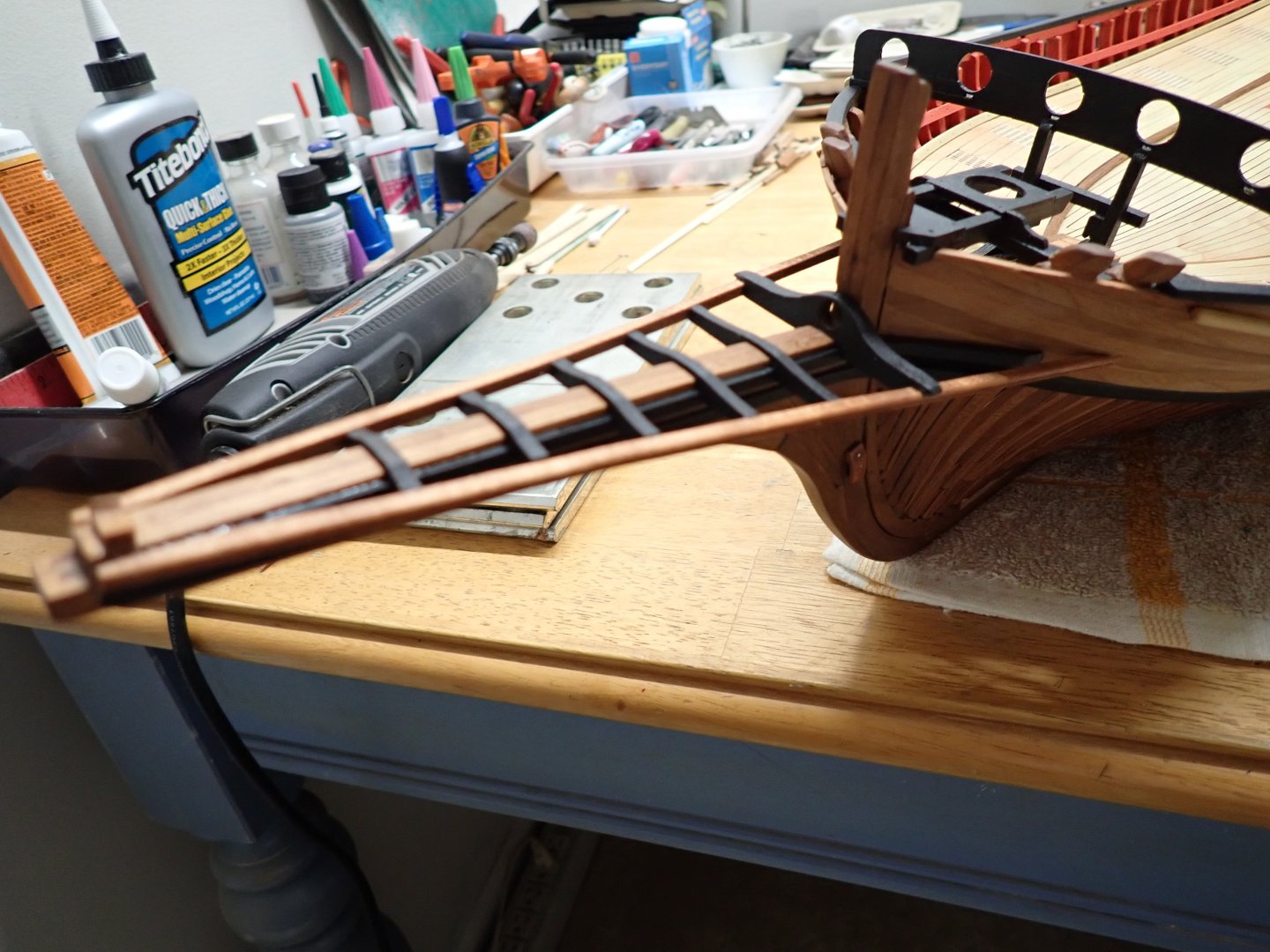
I just completed a very delicate phase of the build: the rudder and tiller. I wanted these to be movable while keeping the capability to take them apart, as this assembly is very fragile. The hinges are photo-etched parts which is not the easiest for making something sturdy and working. The kit of the HMS Bellona offered brass cast parts which are a lot more solid and well designed than what the Chebec kit offers. This is how I approached the conundrum: A small piece of brass ( diameter 1.2 mm) is soldered against the photo etched parts provided in the kit. This is then chemically blackened (and later on painted...) and placed in shape around the rudder: Using electronic components pins, I insert the pins into the wood (diameter 0.7 mm), solder the pins to the PE part in about 4 locations. A little bit of sanding and painting on top, make it look decent. I could not find nails small enough to fit into the PE parts. Of course, while soldering, you want to make sure the wood is not burnt or overheated. It is all very delicate. The female parts going along the stern keel are the most delicate to adjust. Again flat PE not easy to put in form. Here I am using small pieces of tube (material similar to teflon) and I glue them in place along the stern. The rudder pivots very smoothly and there is no jerking. Then the same approach (pins, soldering) is done on the stern, making sure the PE parts are hugging tight the small piece of tubing. Additional CA glue is used to keep everything in line and happy. Verification of the rudder motion: The Boxwood carving is then glued to the rudder and painted black and then dry-brushed with Tamiya gold leaf. CAF Model did a great job at 3D machining this little carving: Once installed, the tiller is inserted into the rudder: The hole is tight enough and holds the tiller without any glue. Motion is possible: Et voila. Needless to say, this assembly is going to be removed, stored and will be back on the model, when is it completed. Yves


- 185 replies
-
- 20
-
-
-
It is hard to imagine the amount of force you would have to apply to a tiller on this type of ship, to steer it in one direction or another. The Chebec I am building is also using a massive rudder and a long tiller. Yves
-
Excellent decision !!! Too many projects to justify loosing sleep with a single one. Yves
-
Great video and incredible models, in that scale. Thank you for the link. Yves
-
Chris, You may know more than I do about this specific kit manufacturer, but I can give two clear examples of the kits I have and am building and no build log of them can be found online: CAF Model HMS Bellona and CAF Model Le Chebec. The Kits made by CAF Model are excellent (in my opinion) but rather difficult and poorly documented. Definitely not something I would recommend to a beginner. What happens quite often, is that potential builders will get excited about a kit and later on realize that they cannot complete it or loose interest in it. We all have had to deal with this kind of problems. Yves
-
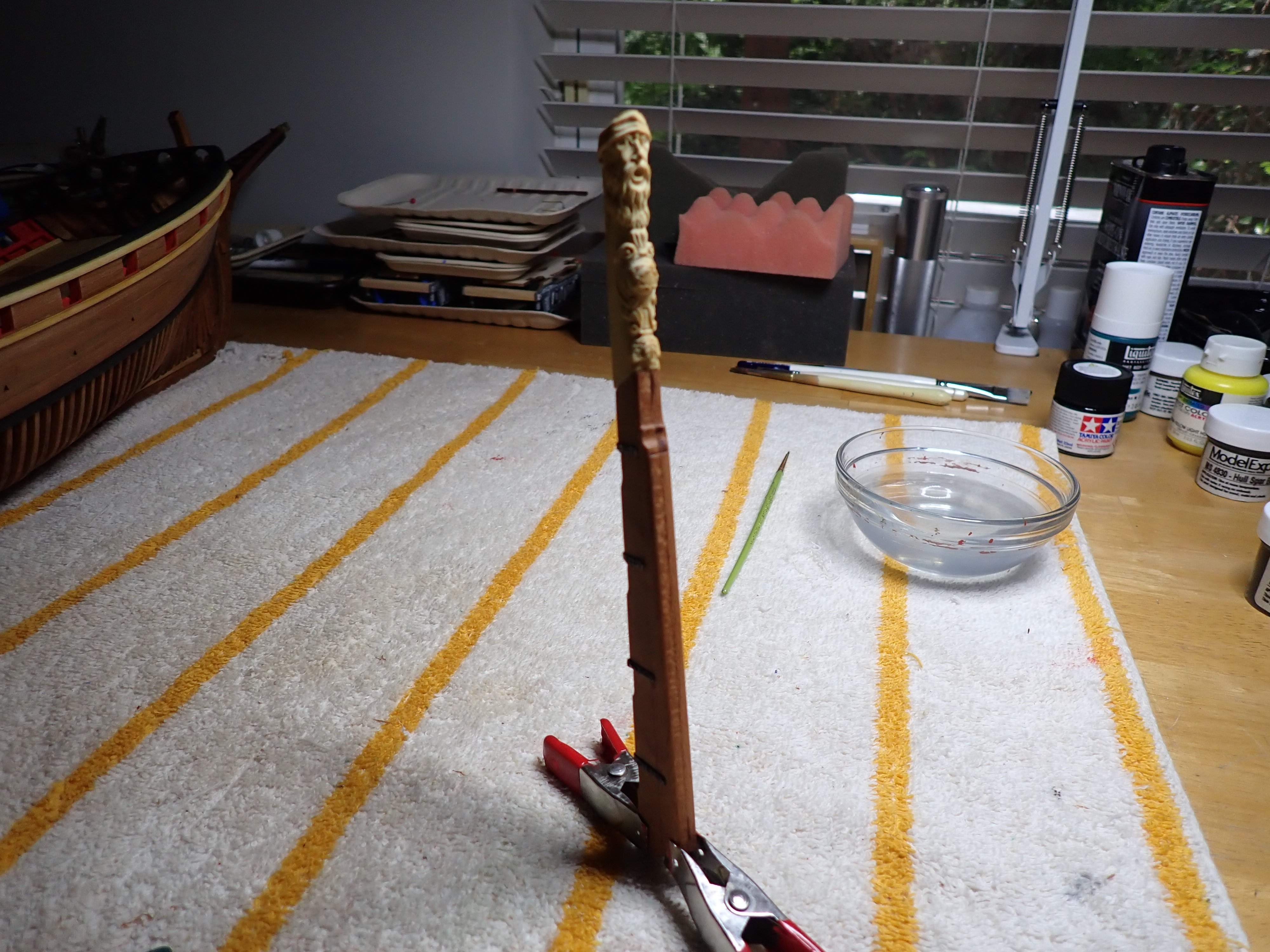
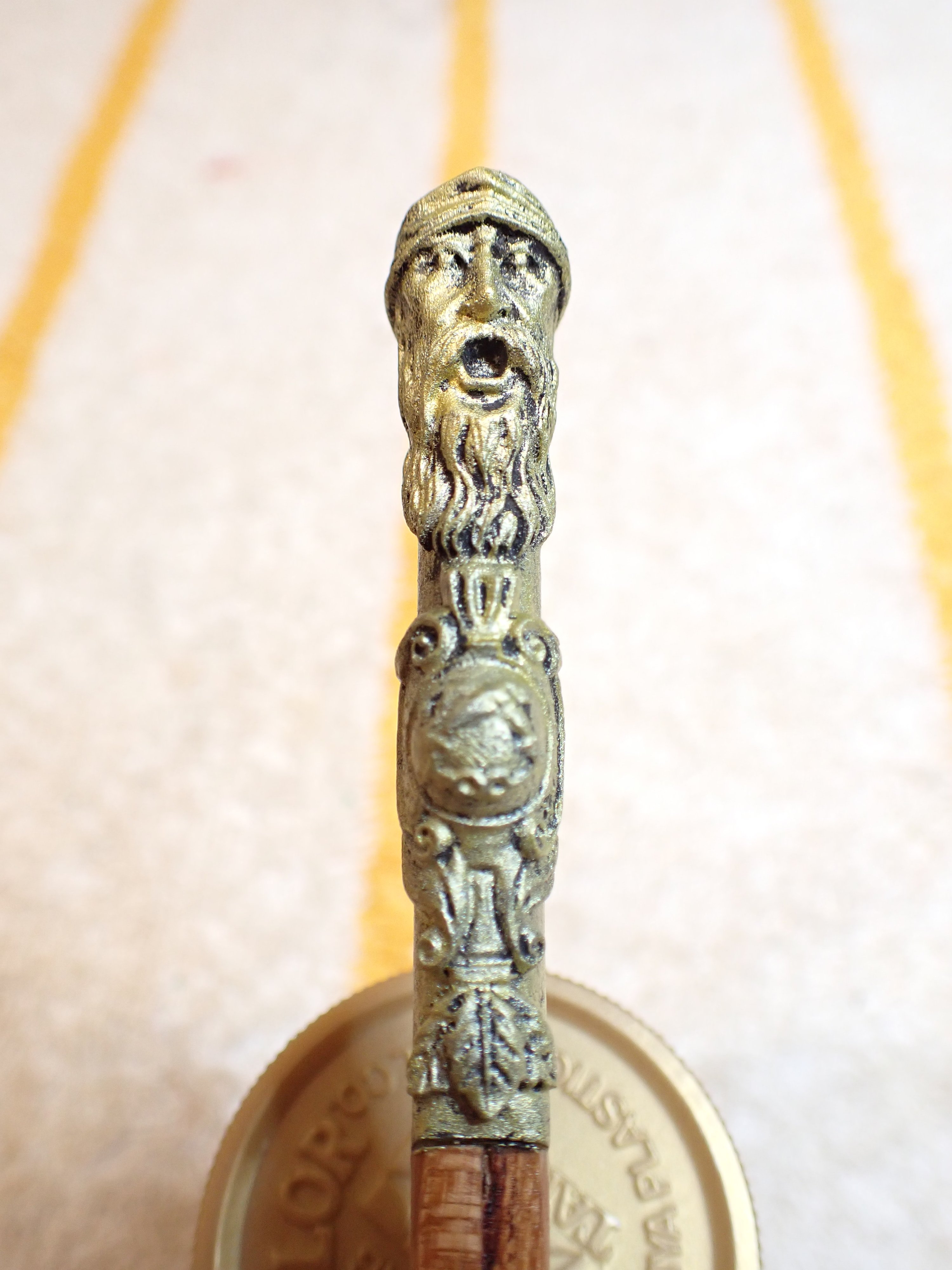
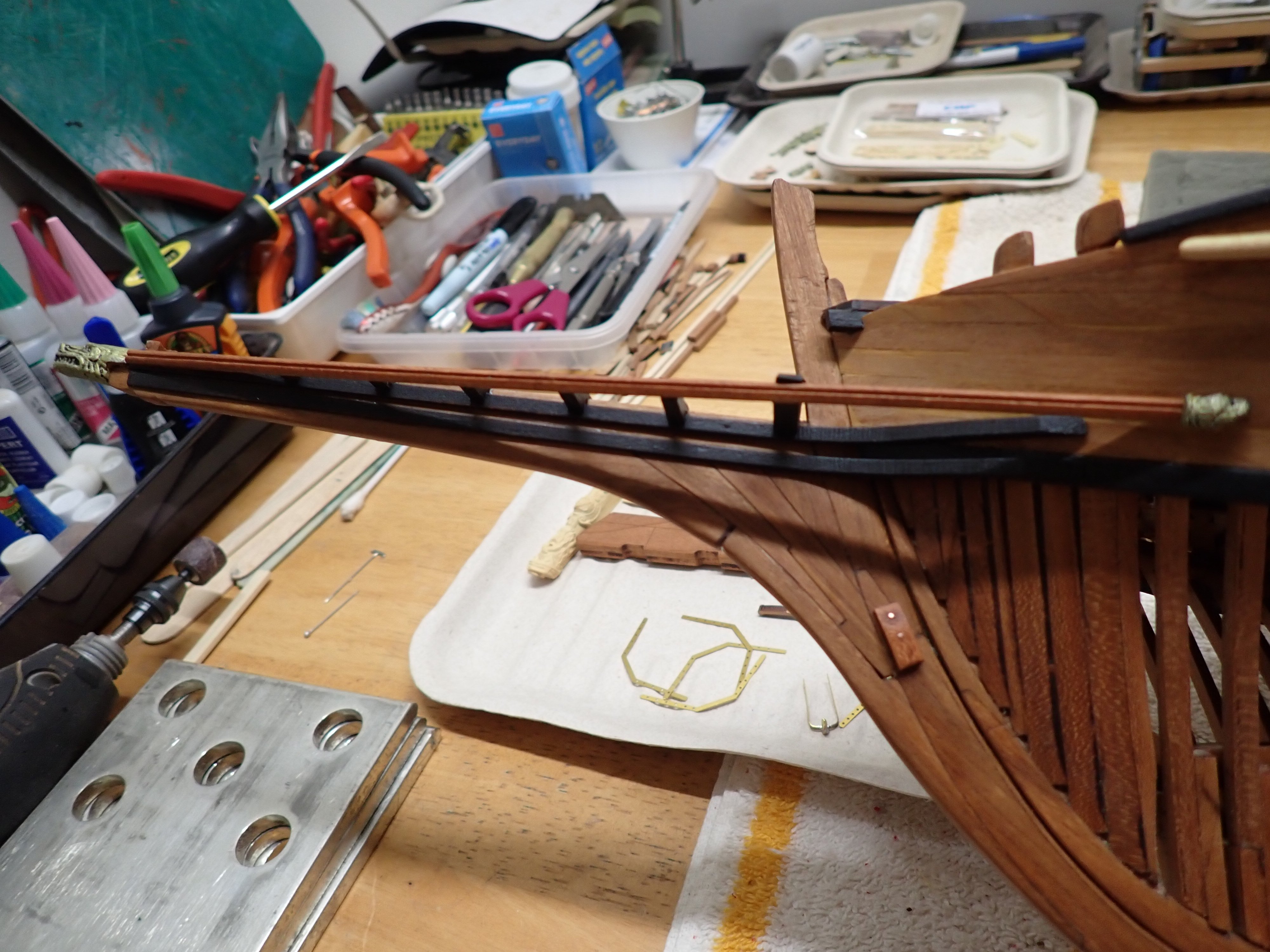
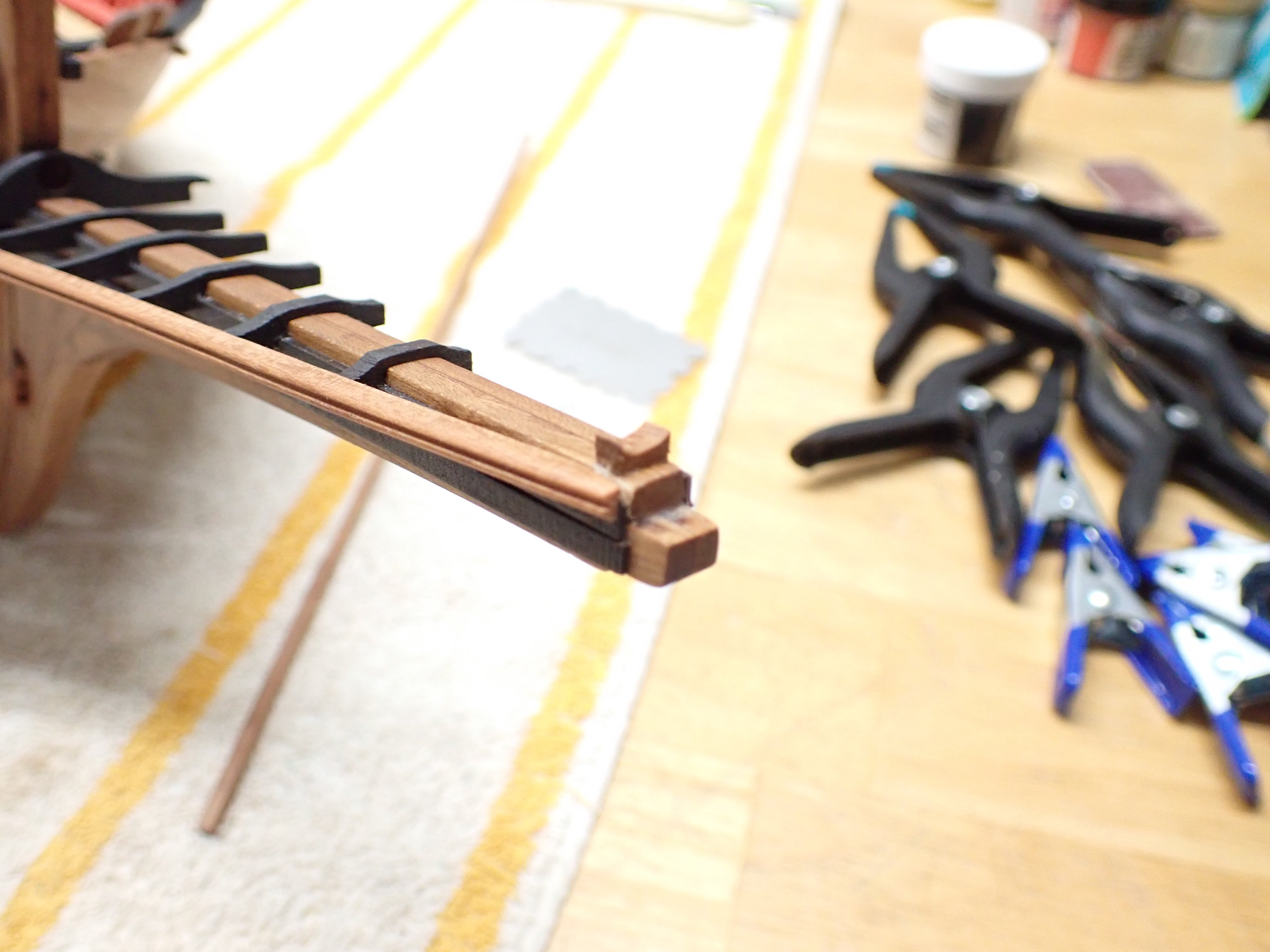
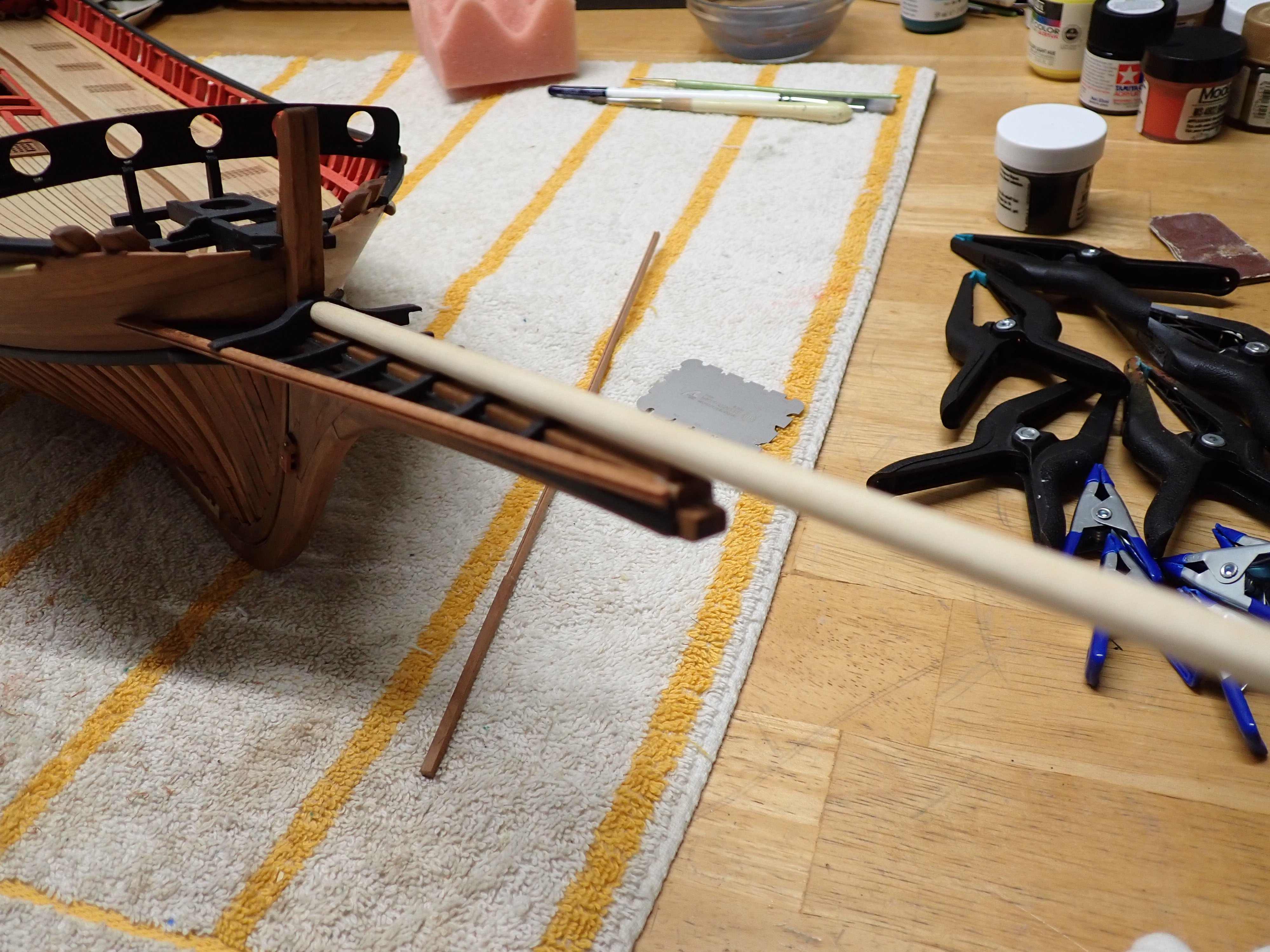
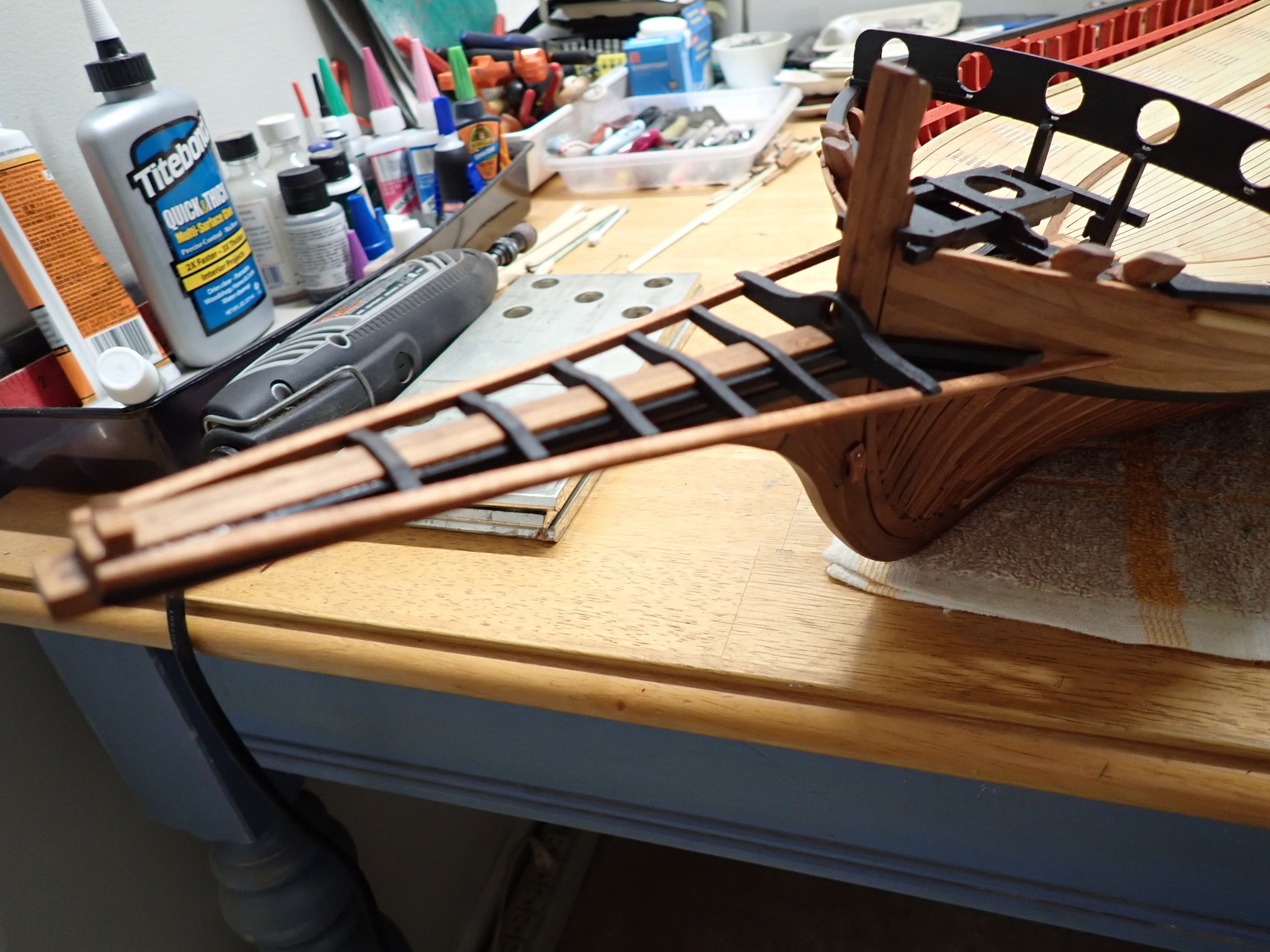
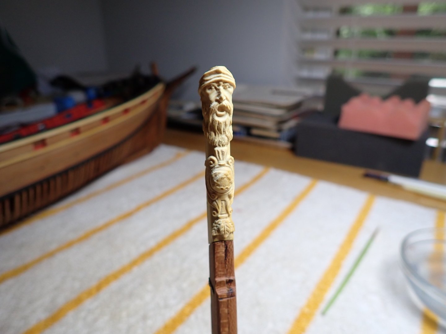
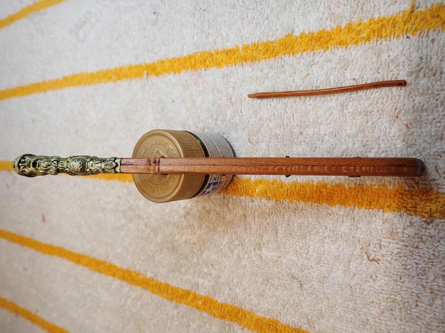
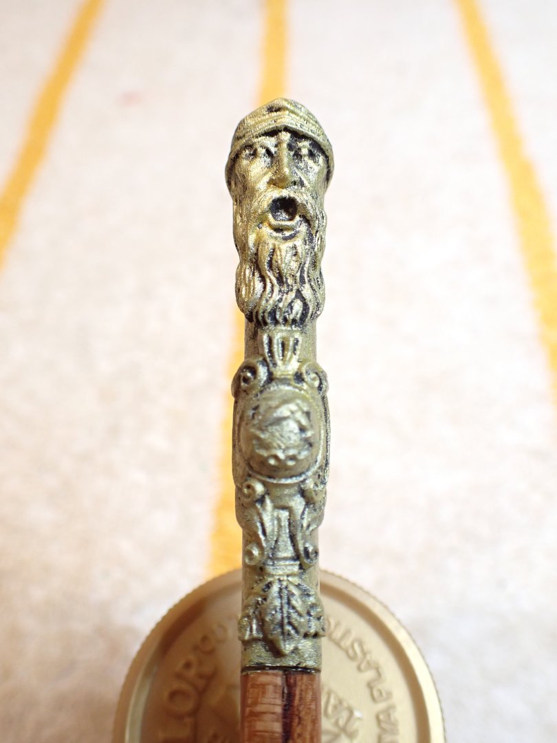
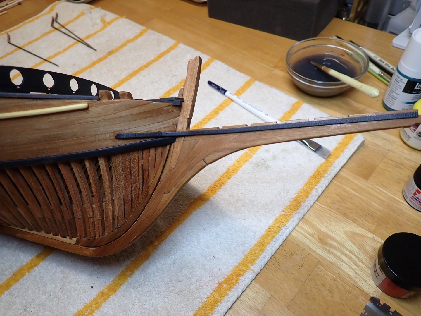
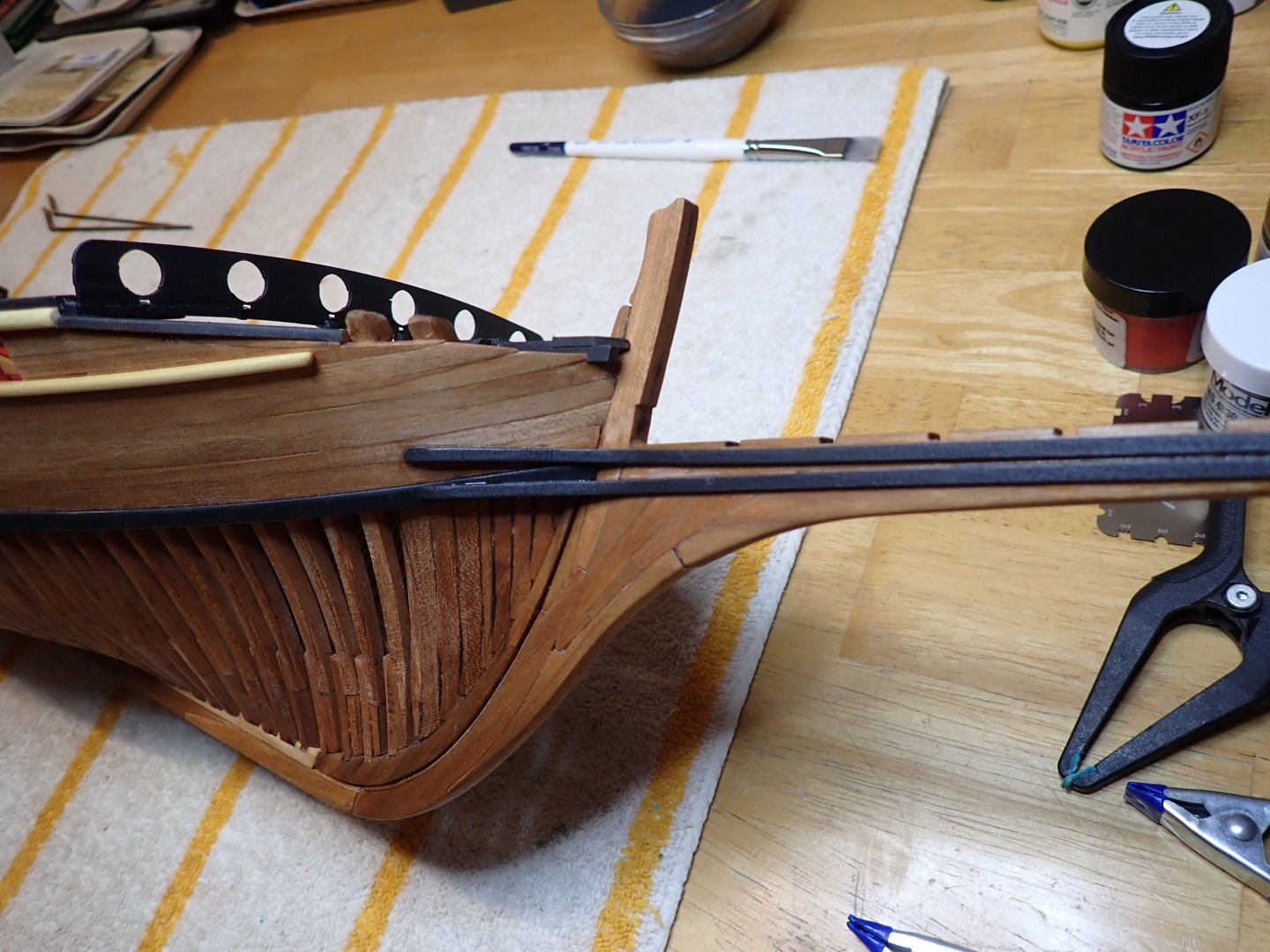
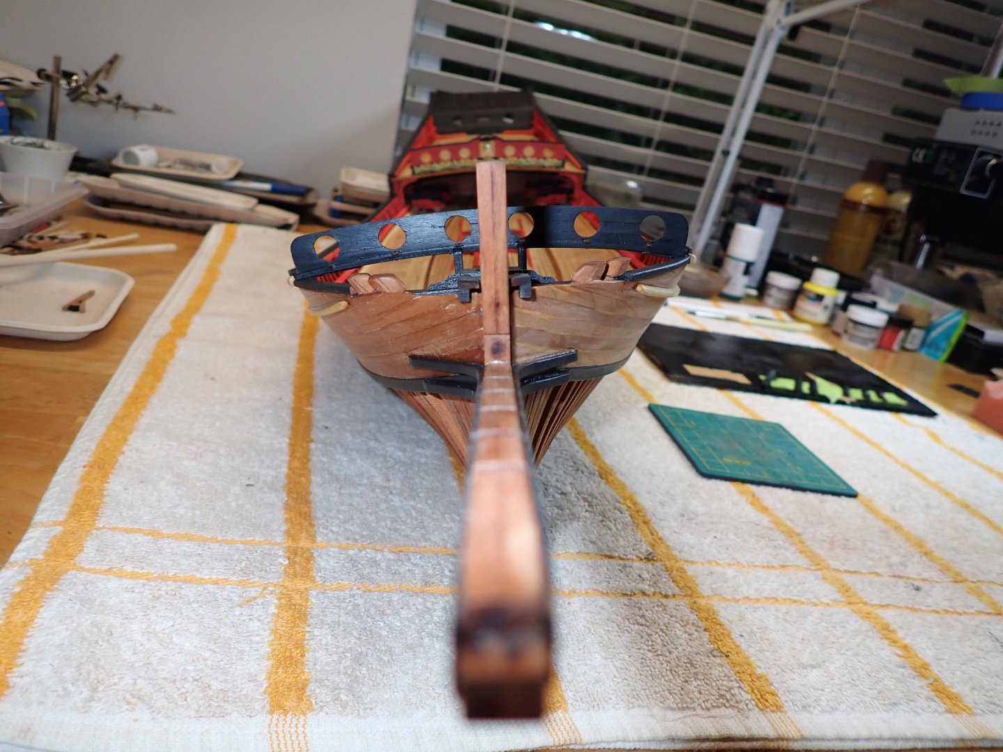
A few progress on the bowsprit: This is a delicate assembly and I approached it in stages: The tiny part above is not included in the kit, but helps tremendously in stabilizing and aligning the front bowsprit. Highly recommended. The figures have not been installed yet, as I am afraid to damage them (at least the one sitting on the tip of the bowsprit). Yves


- 185 replies
-
- 17
-
-
-
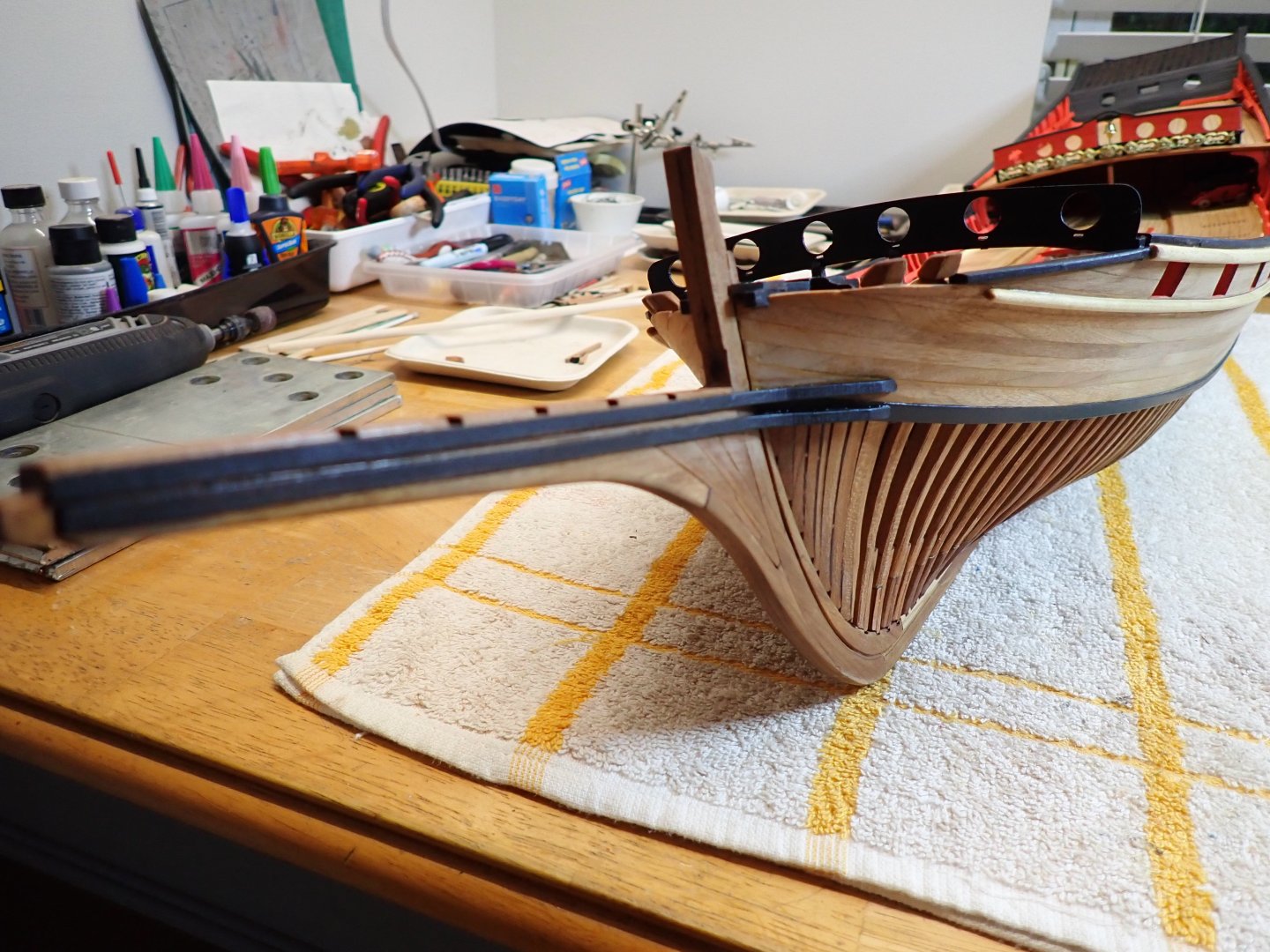
It is definitely "punching" through the water..... 😄 Yves
- 51 replies
-
- 1
-
-
- Puncher
- escort carrier
- (and 1 more)
-
Beautiful planking. There is a lot of care going into it and it shows. Yves
- 62 replies
-
- 3
-
-
-
- Nordkap
- Billing Boats
- (and 1 more)
-
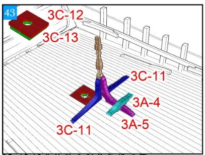
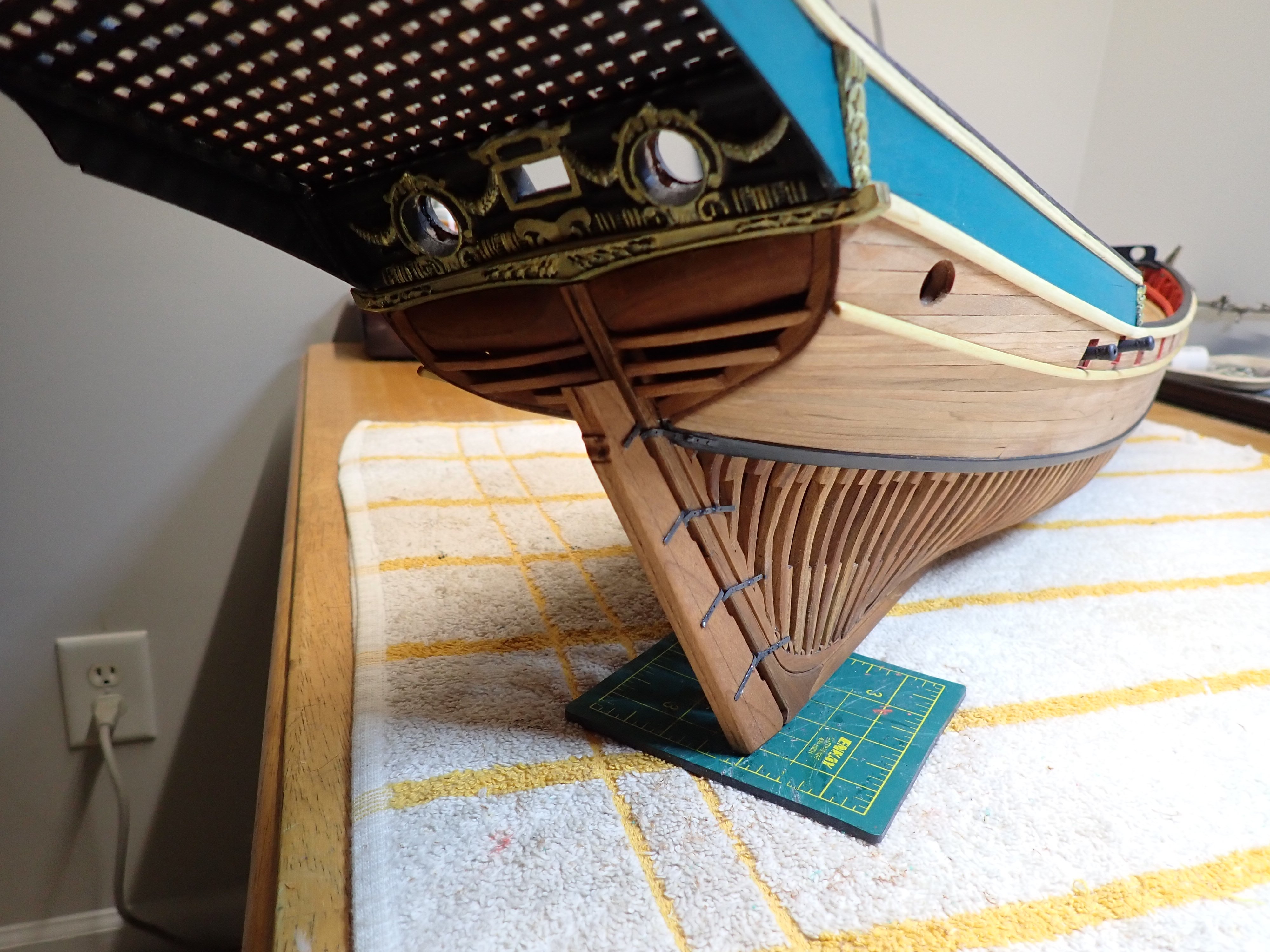
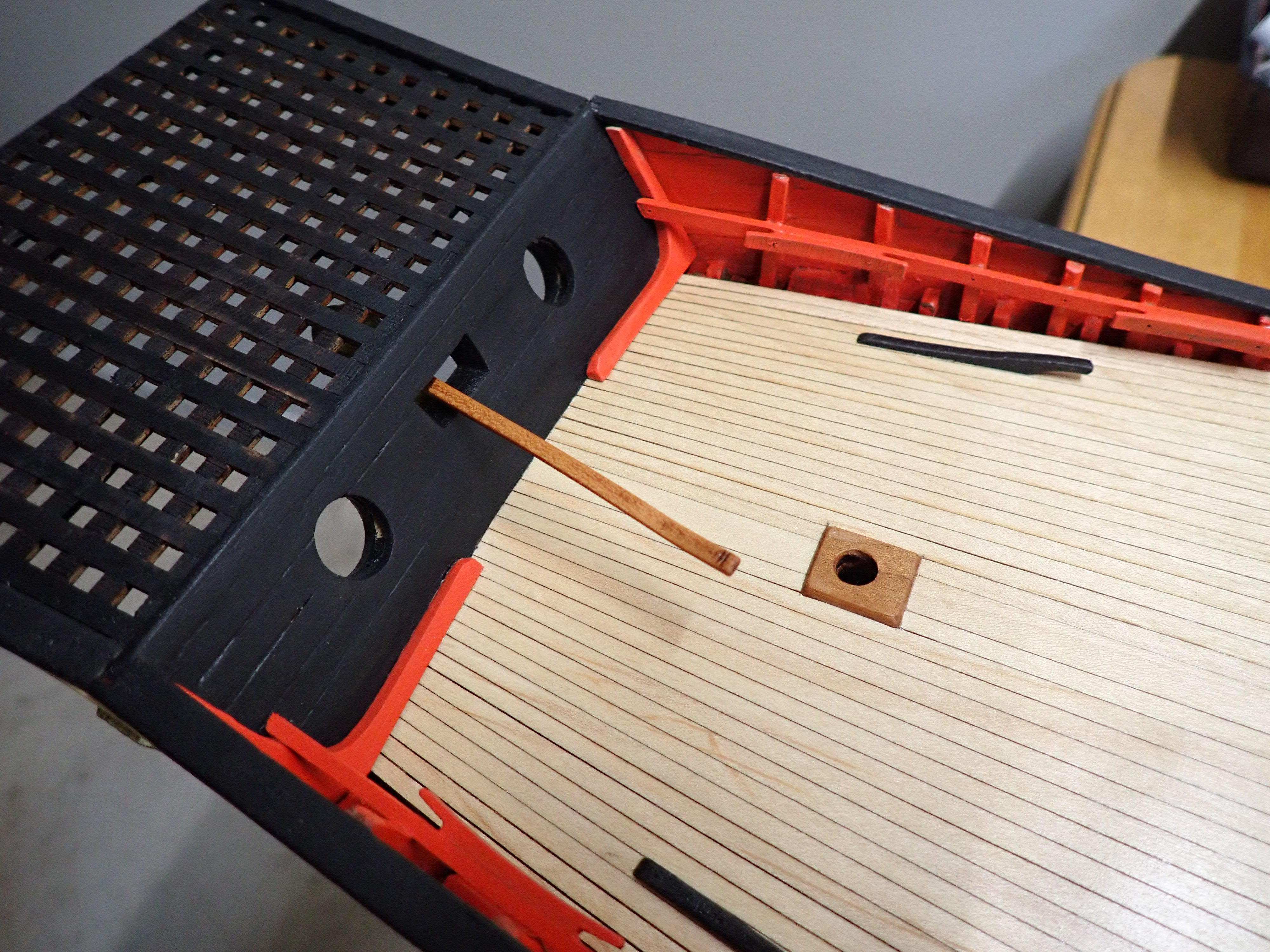
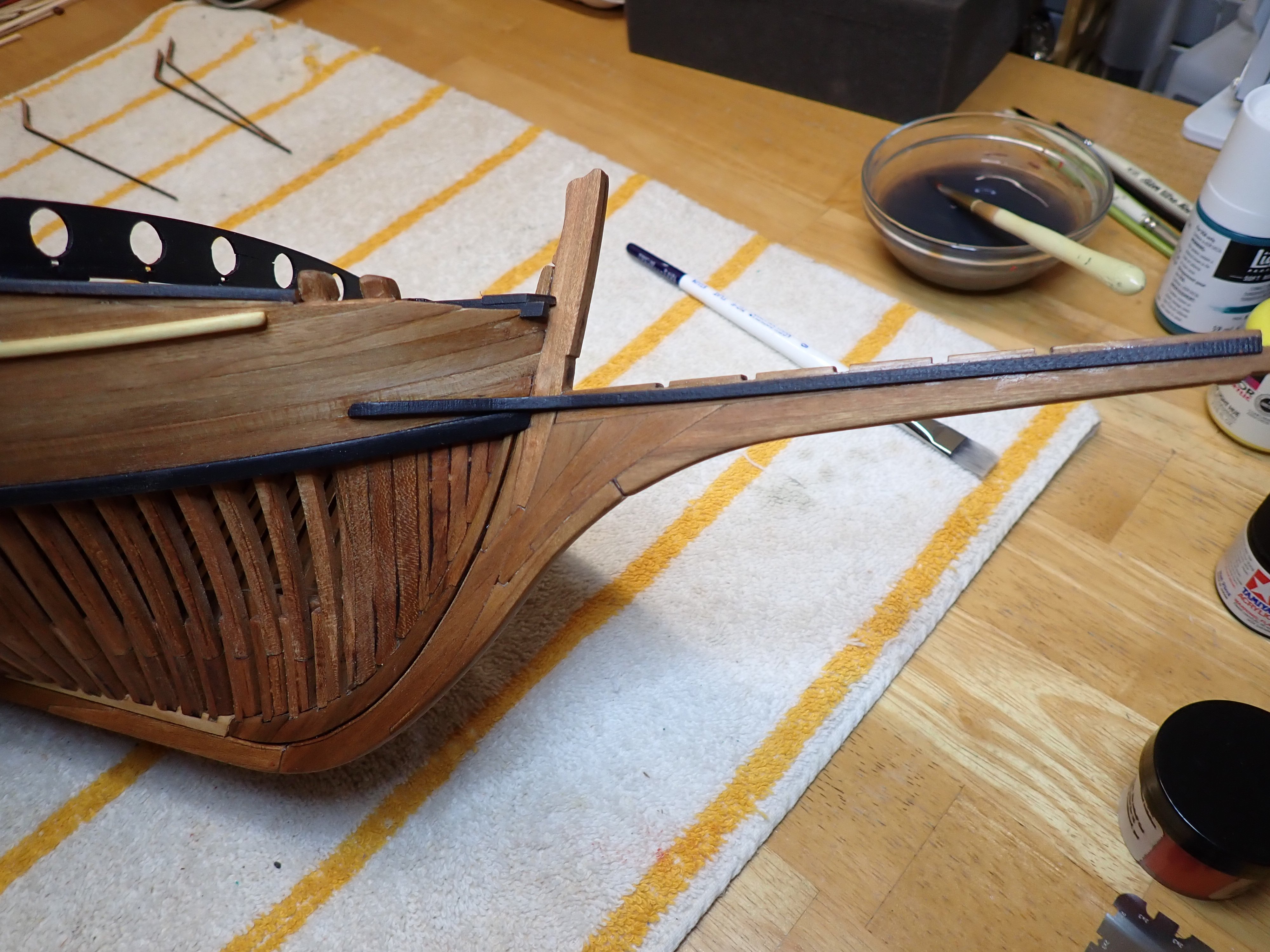
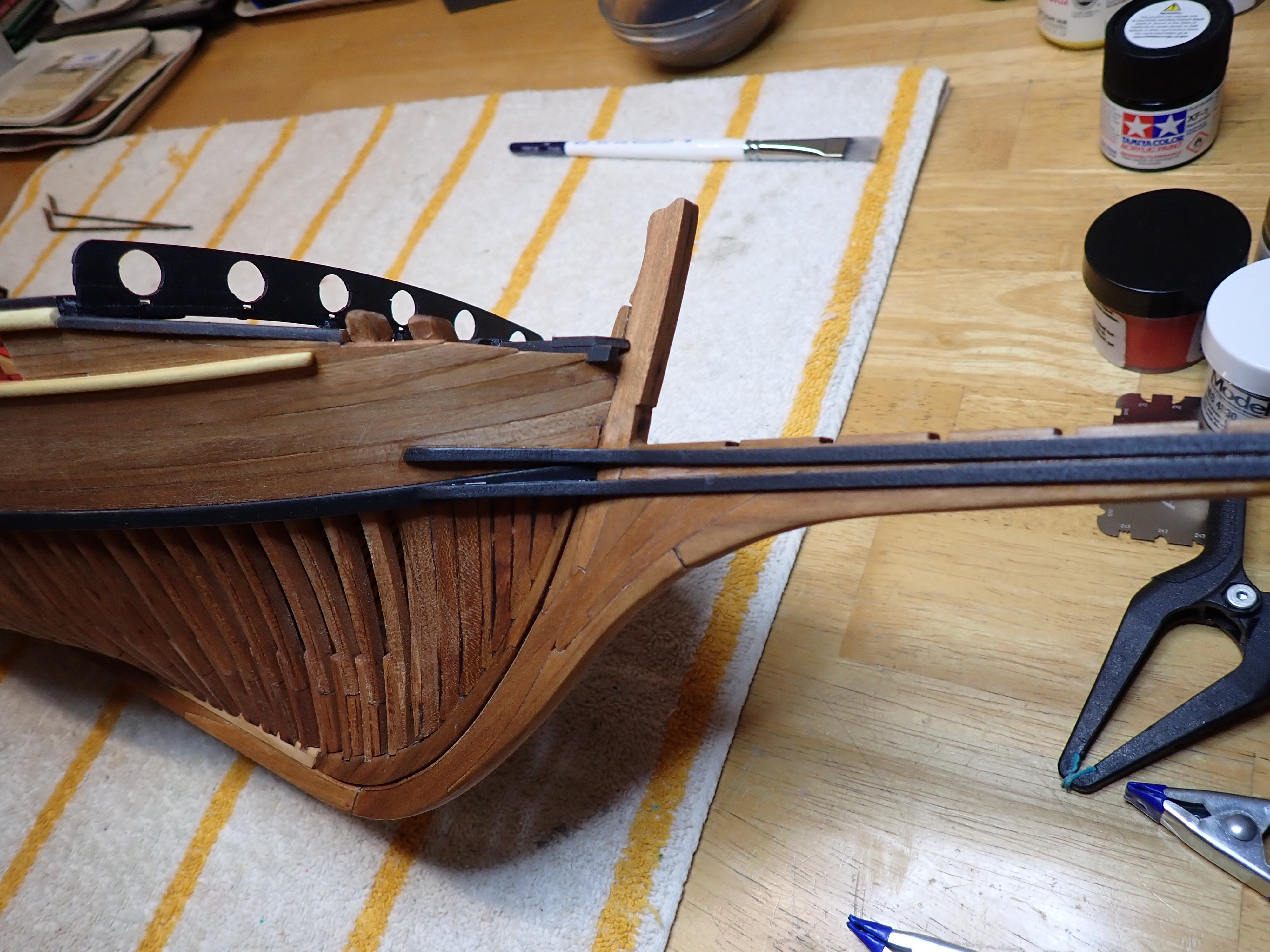
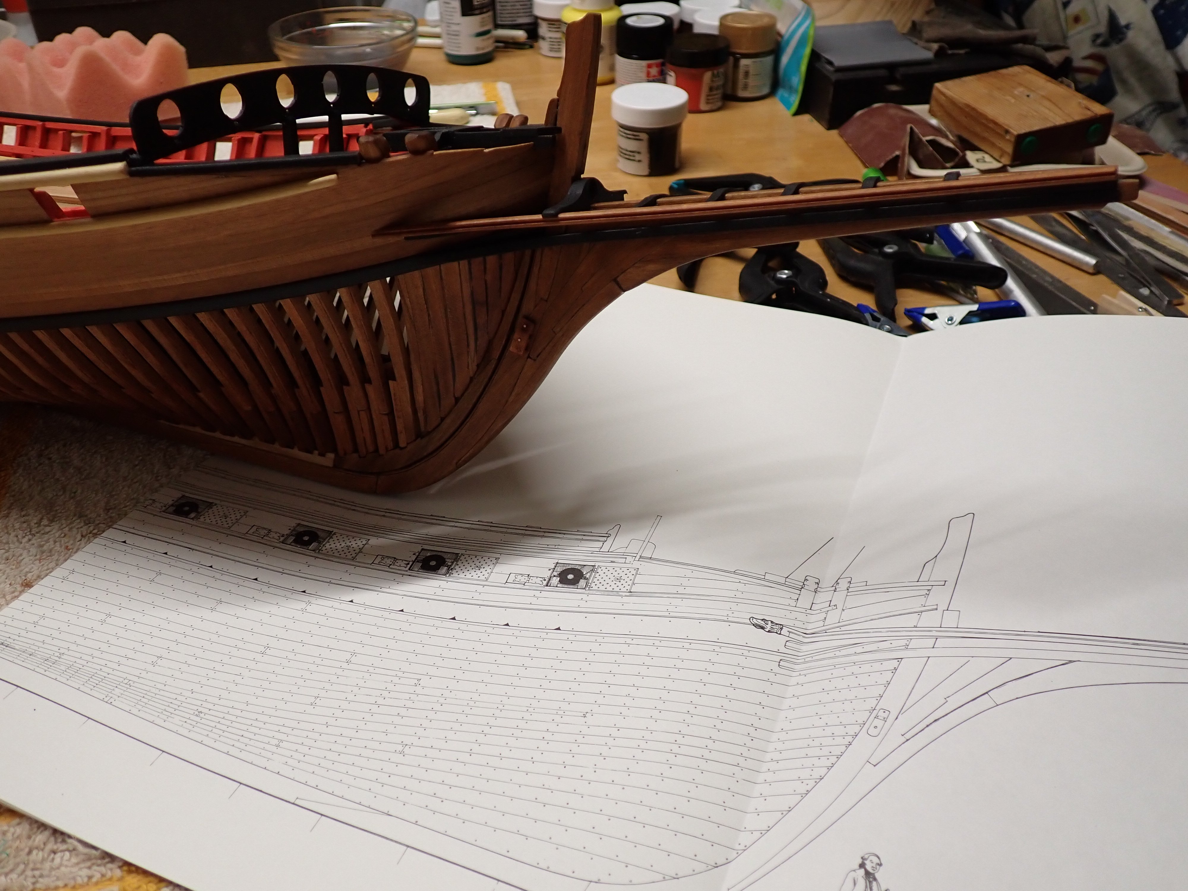
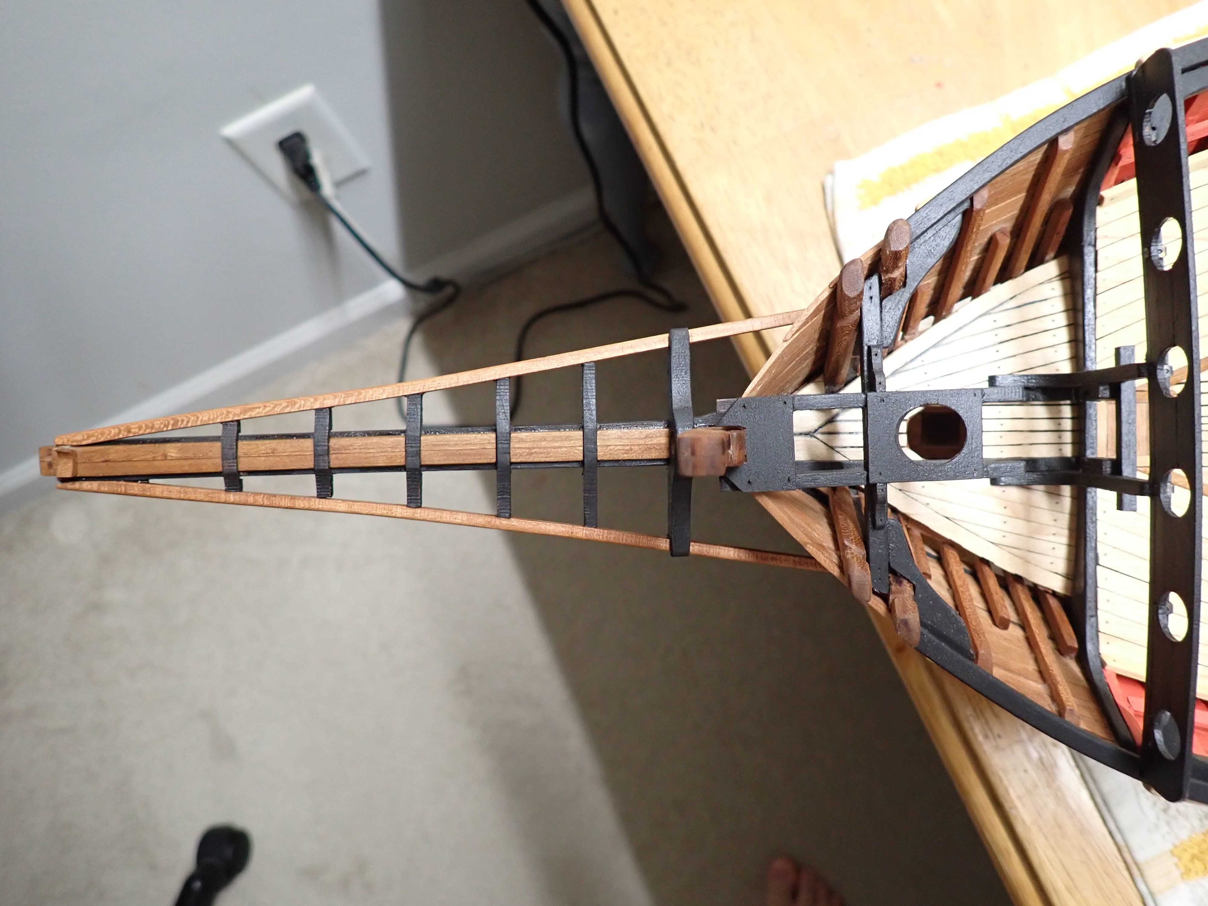
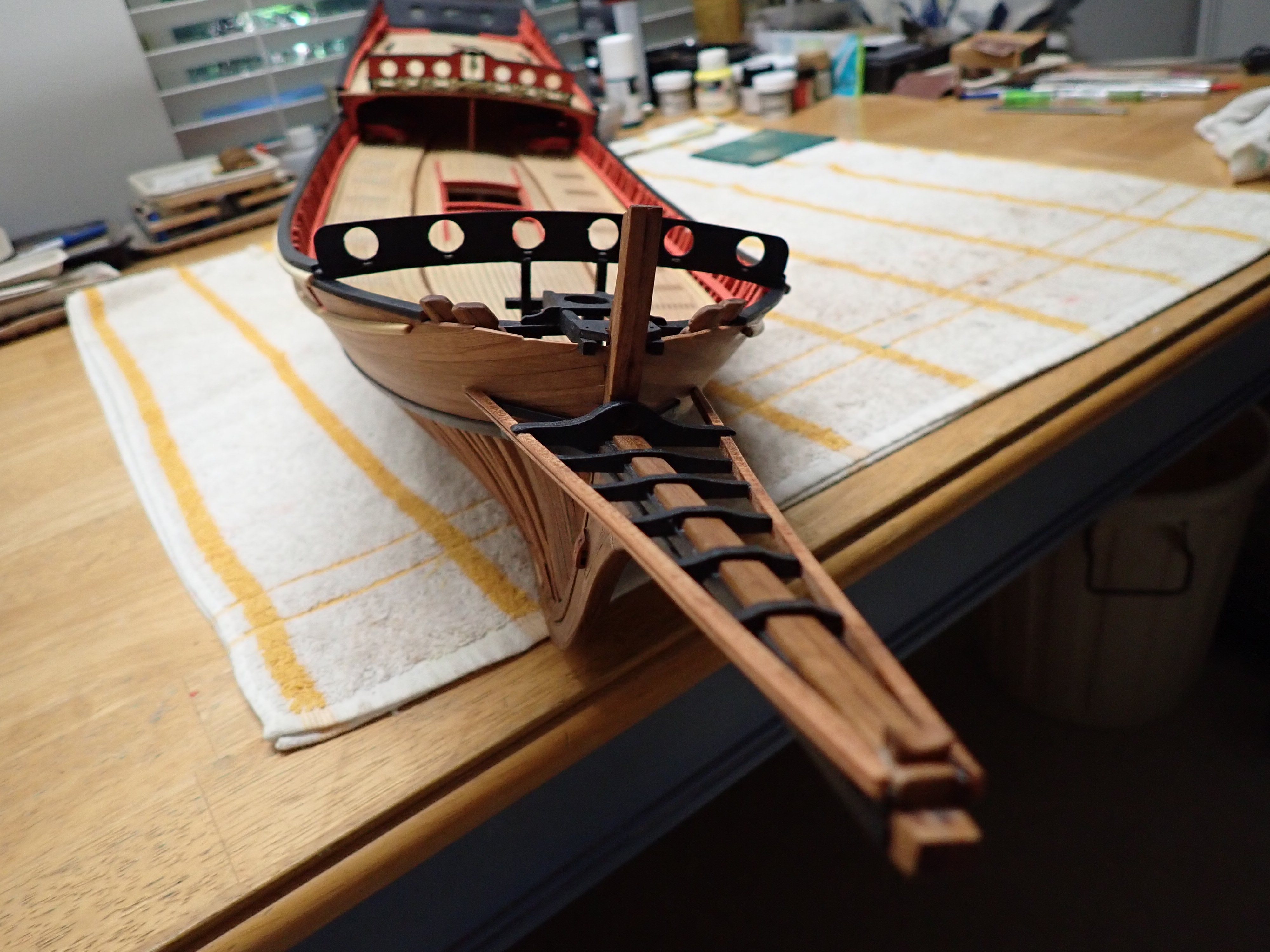
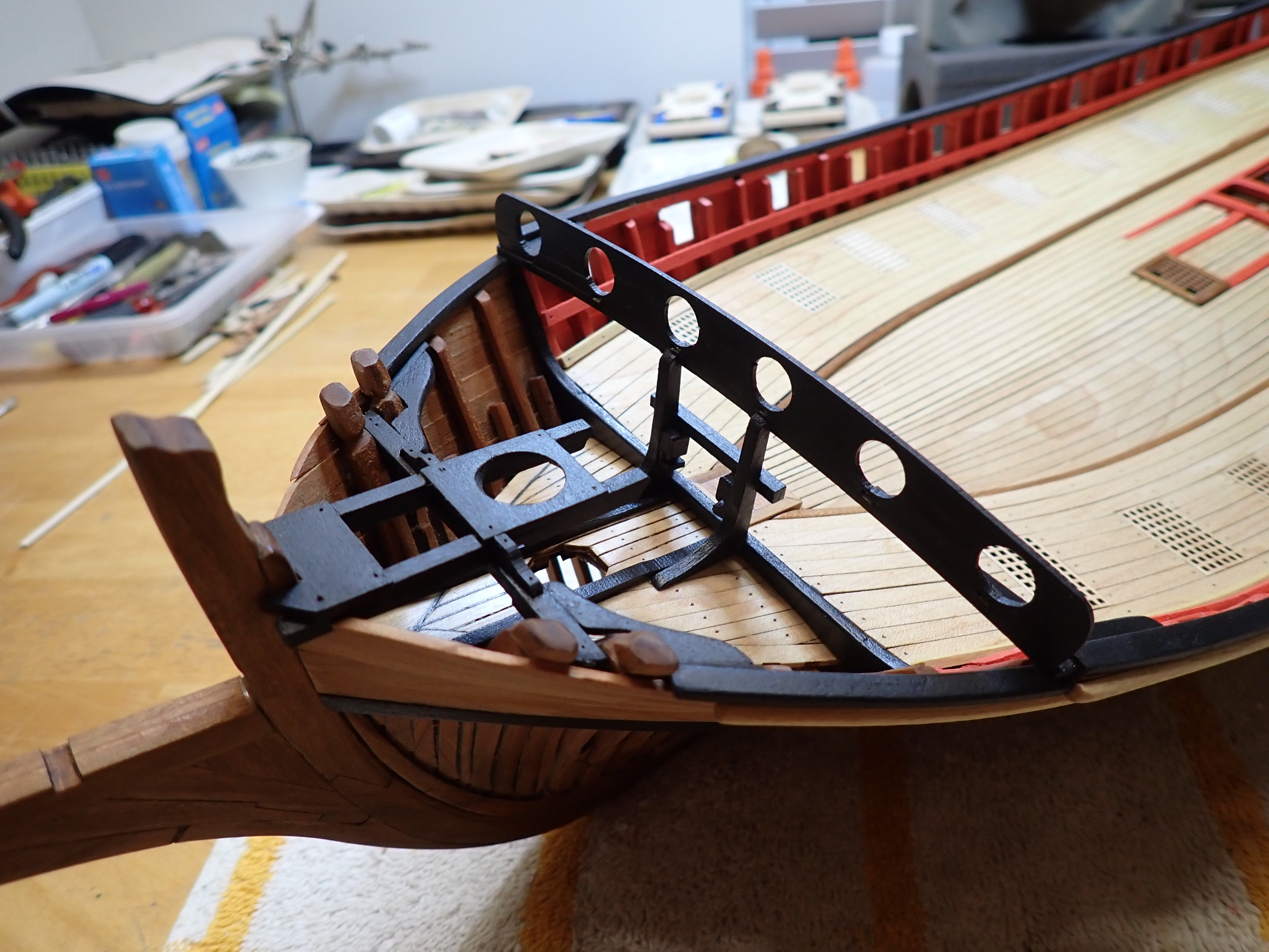
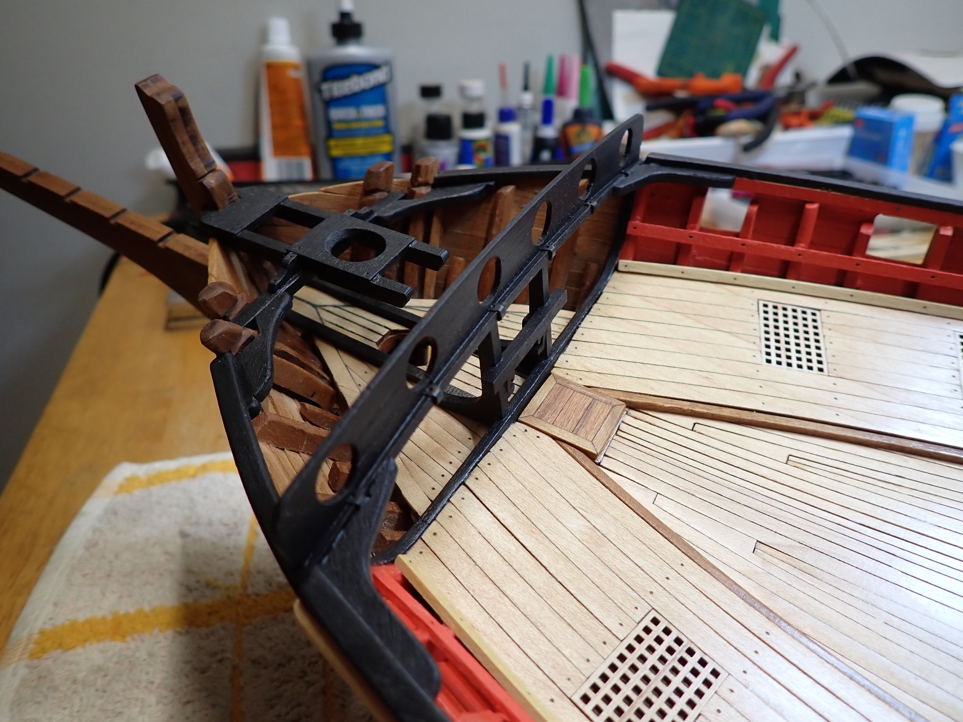
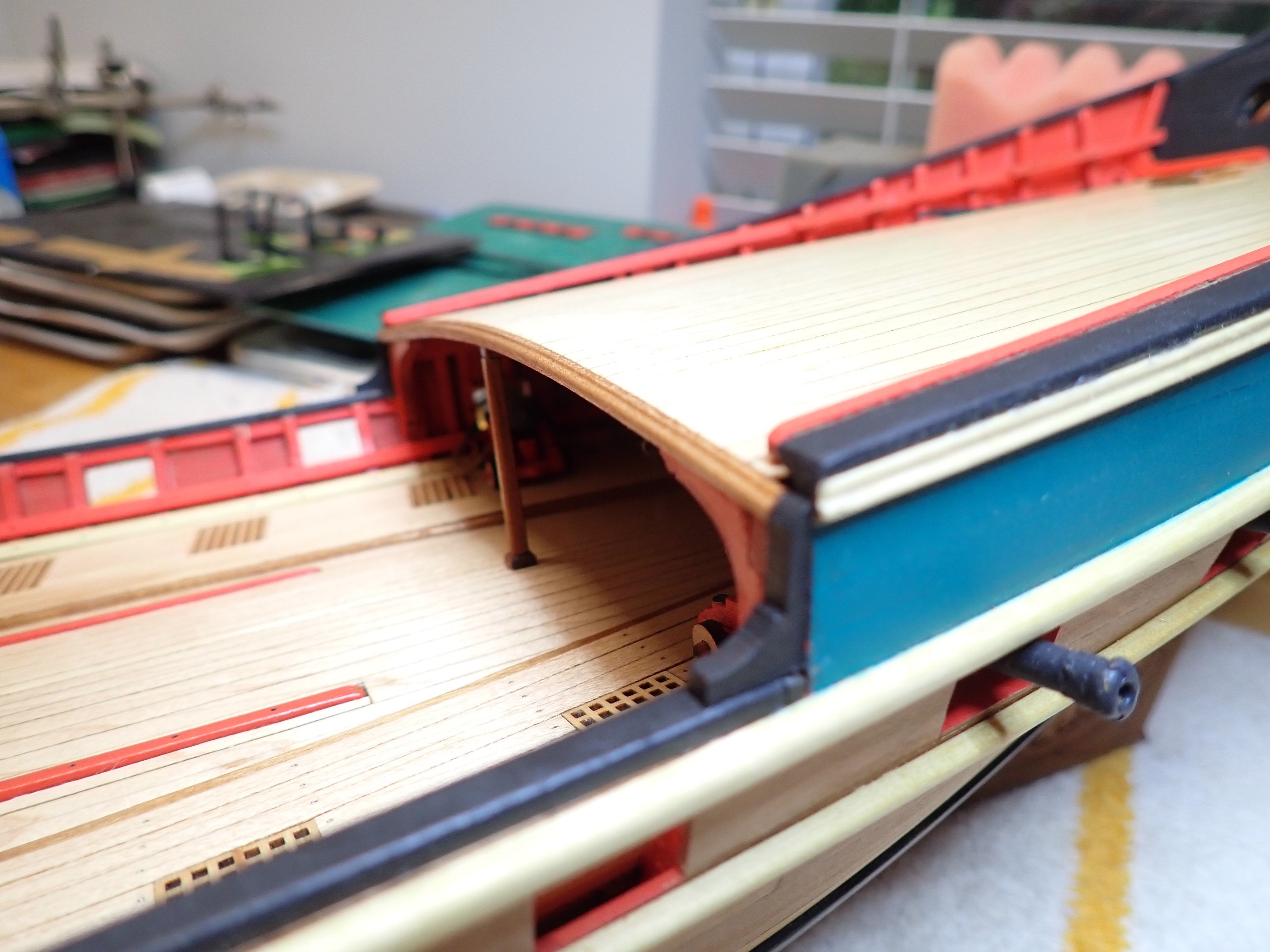
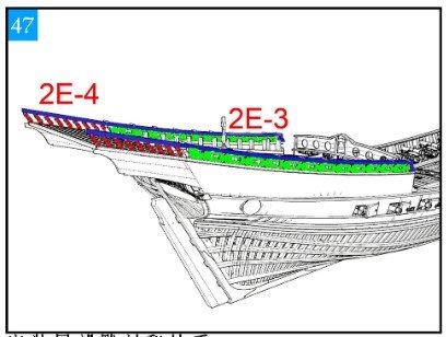
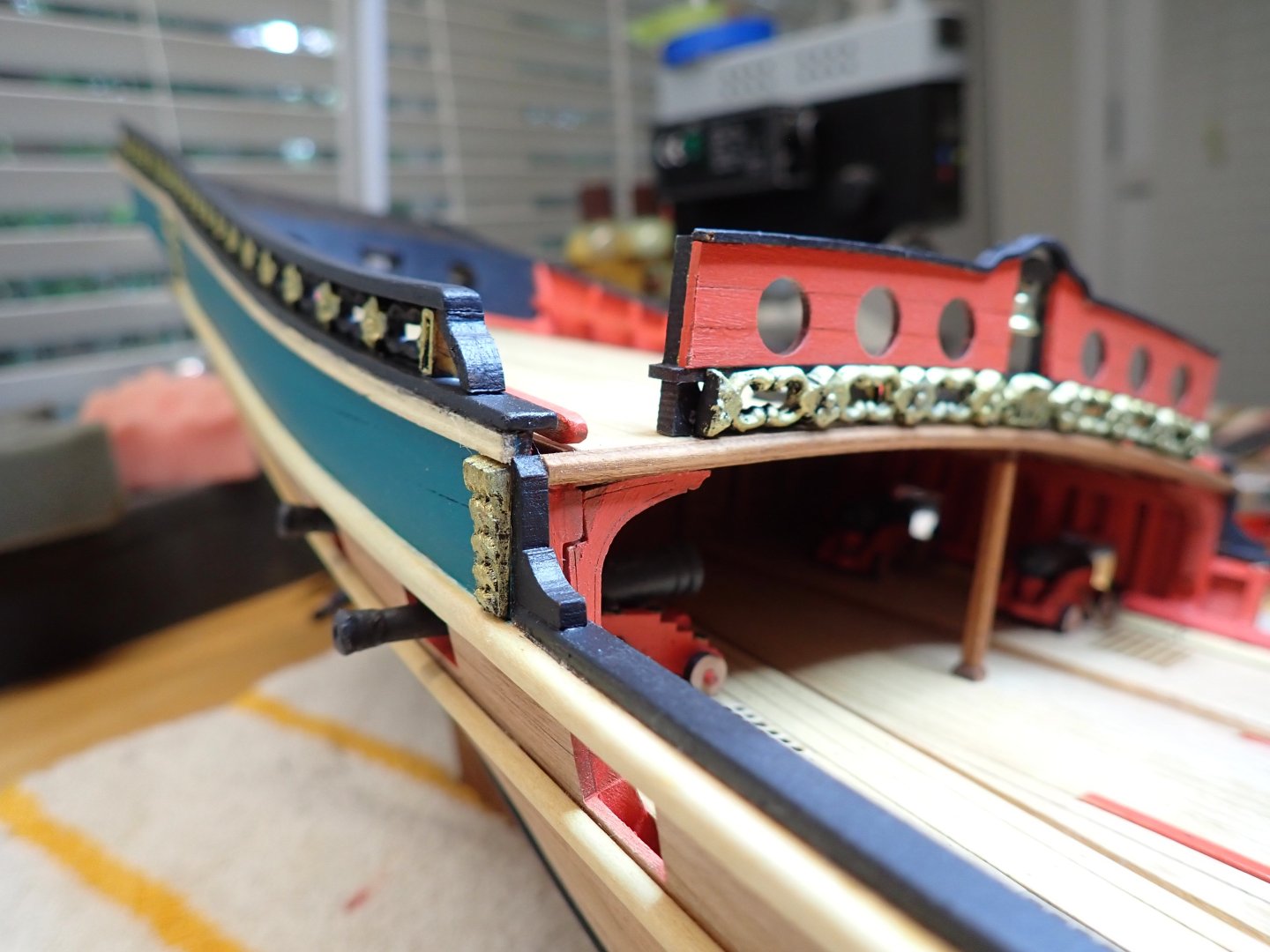
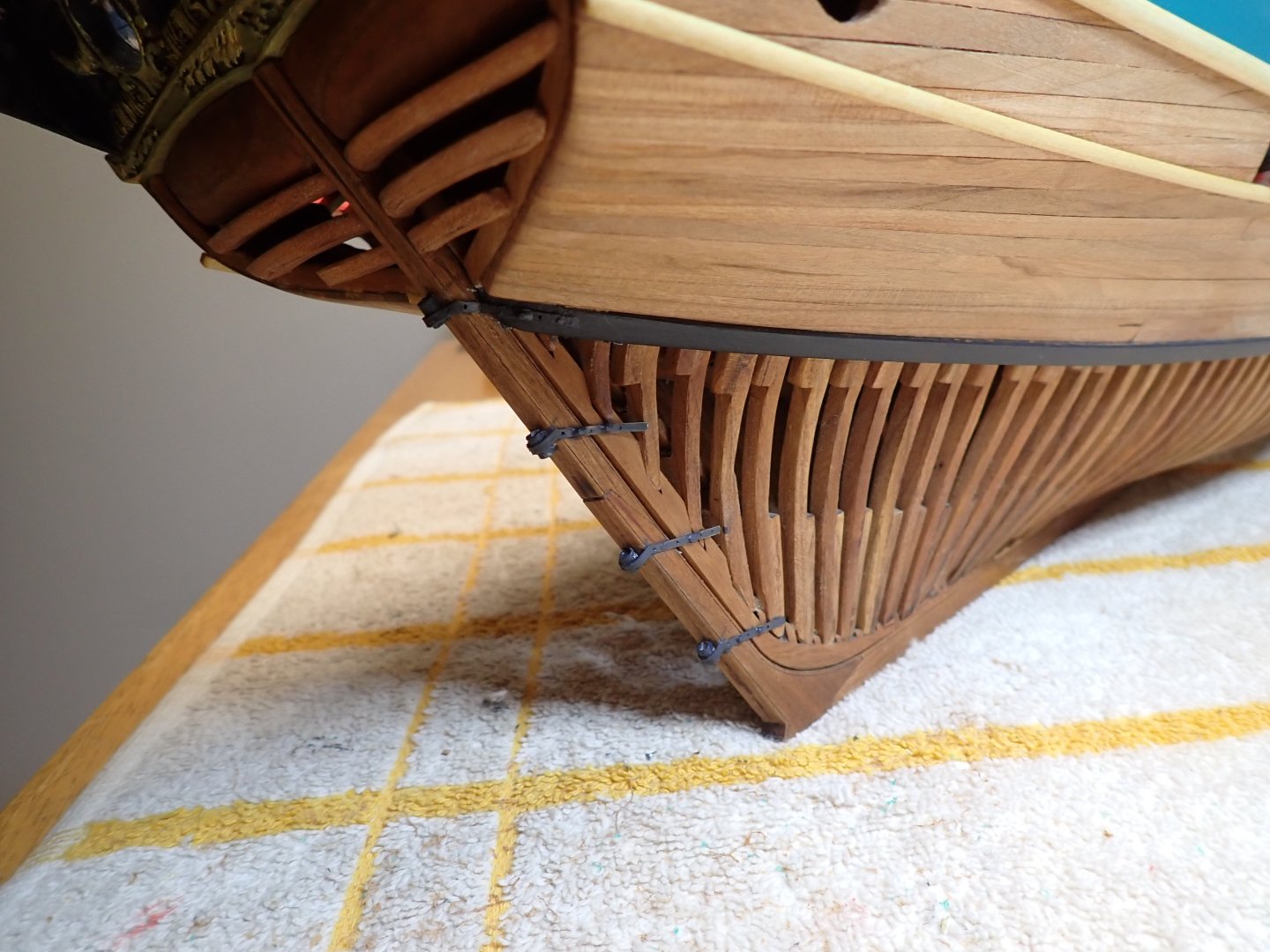
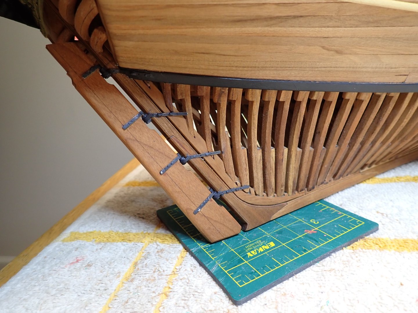
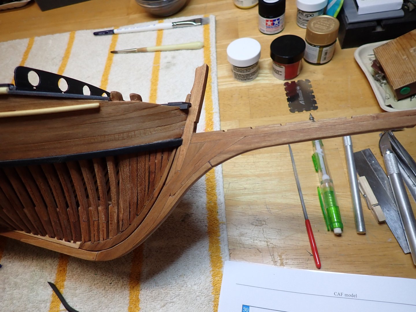
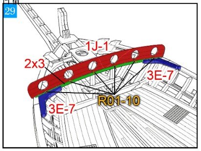
Moving our attention to the bow. For Javelin, a few more round holes.... Each hole has a tiny PE part located at the bottom, and used as a holder for a portable cannon. The hand held cannons are not part of the kit, but I have seen some models with them. I really like the intricacies of that bow, with its tilted mast. It makes for a rather interesting and unusual section of the ship. And the overall view.... Yves

- 185 replies
-
- 15
-
-
-
-
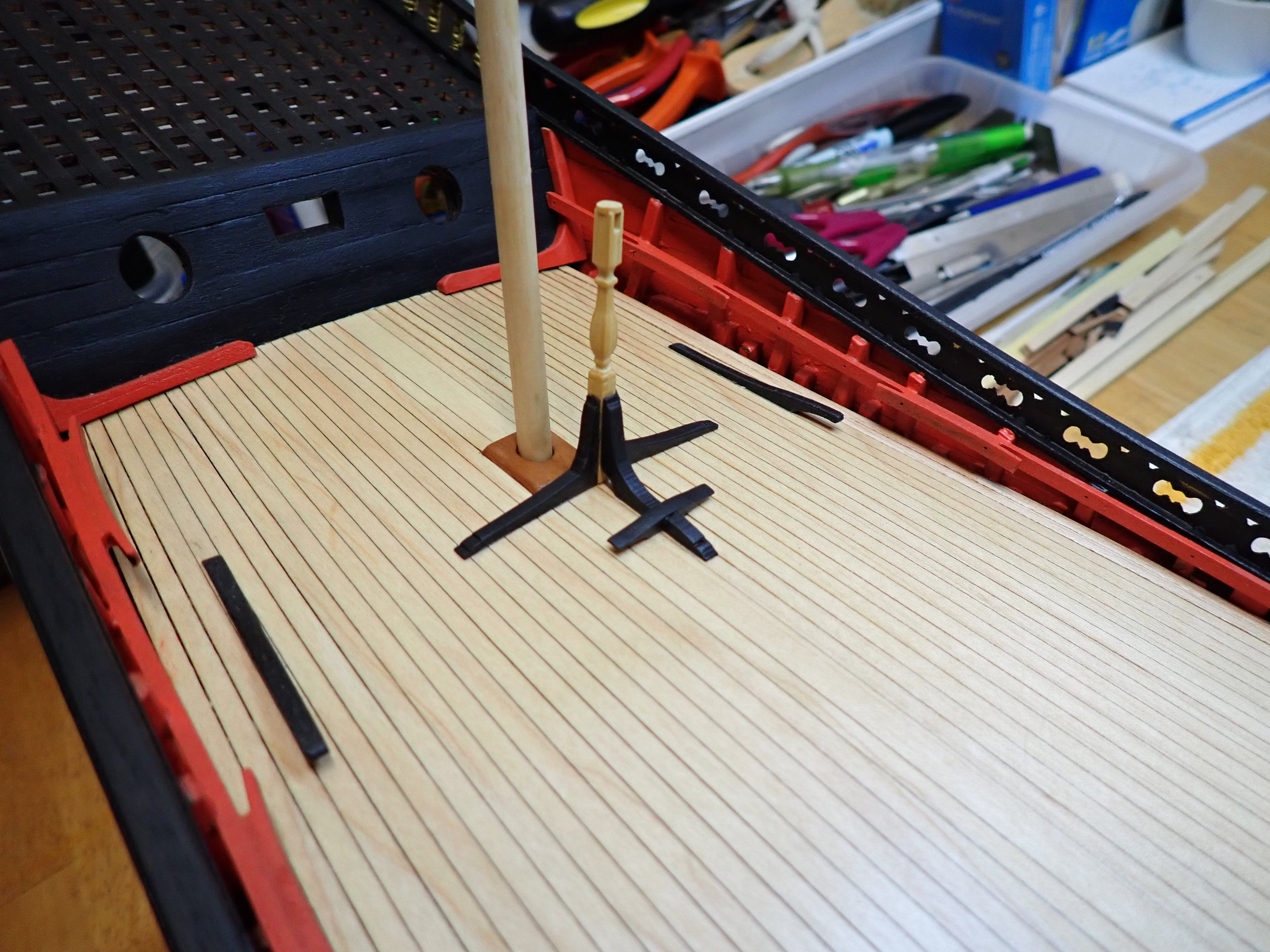
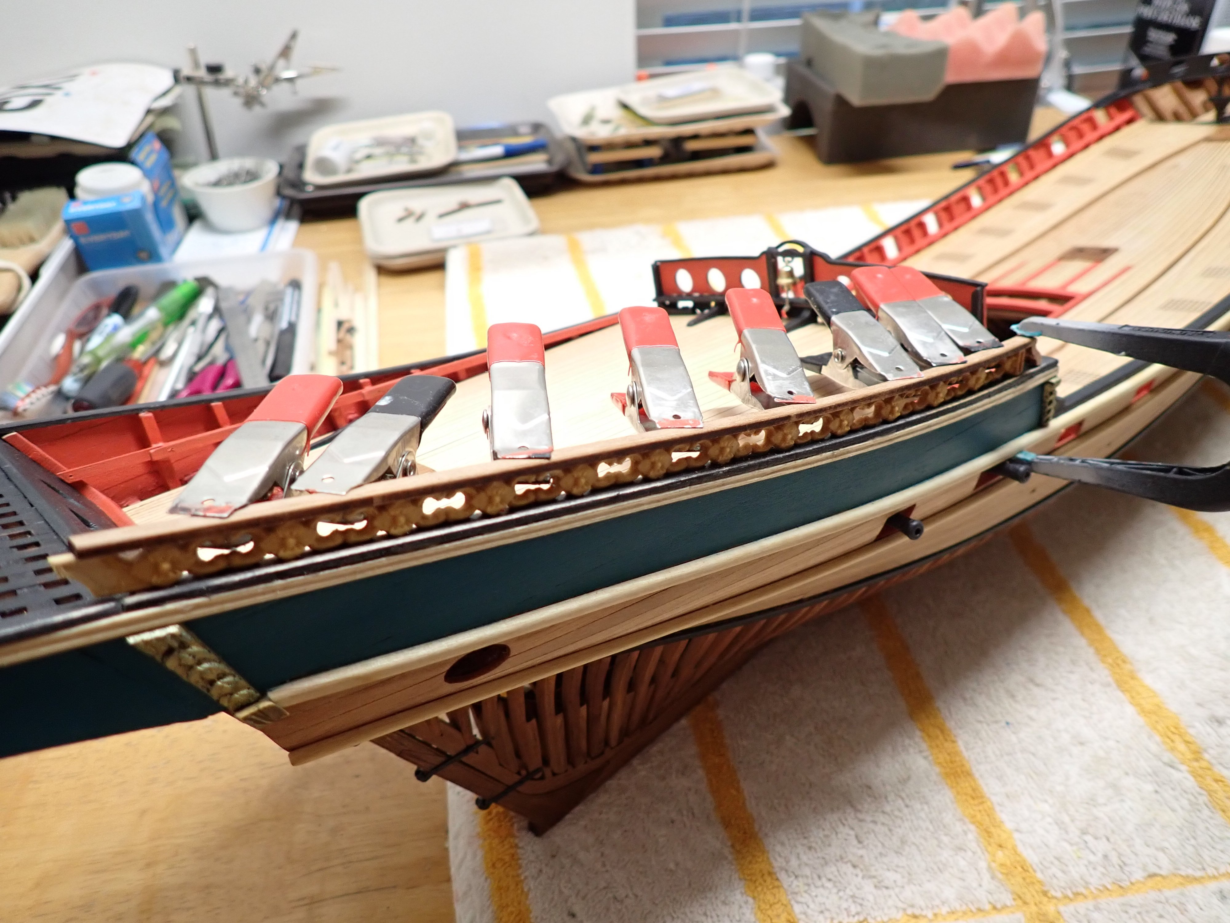
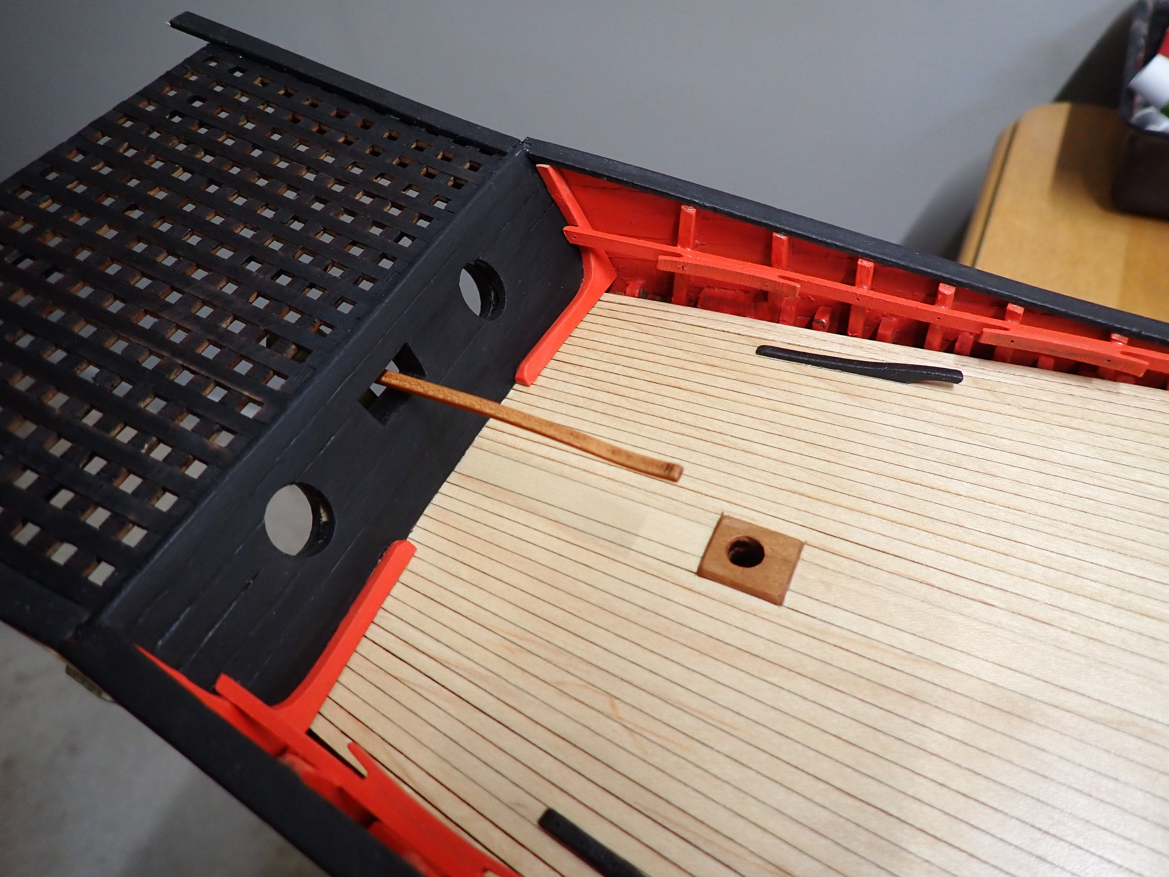
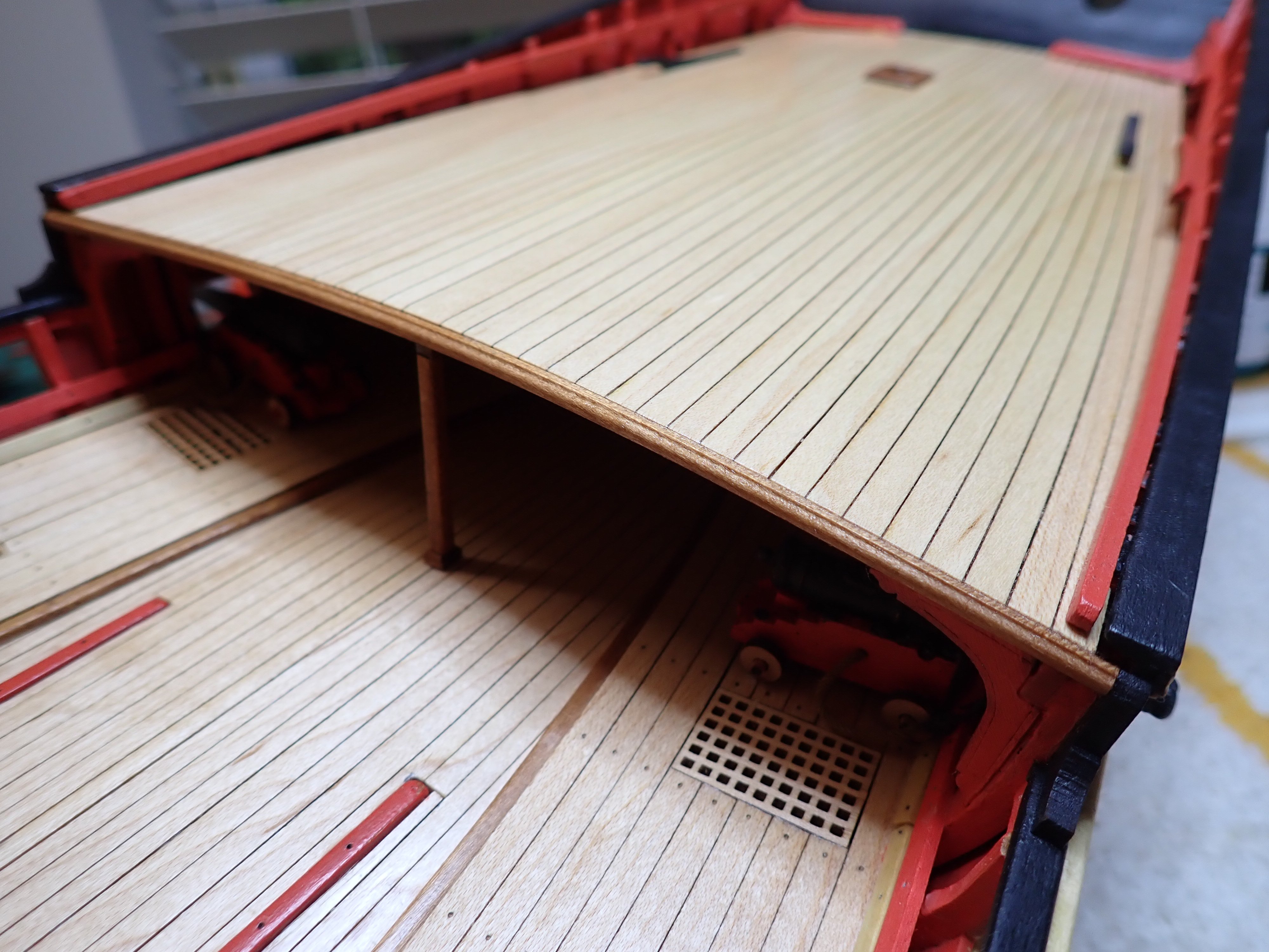
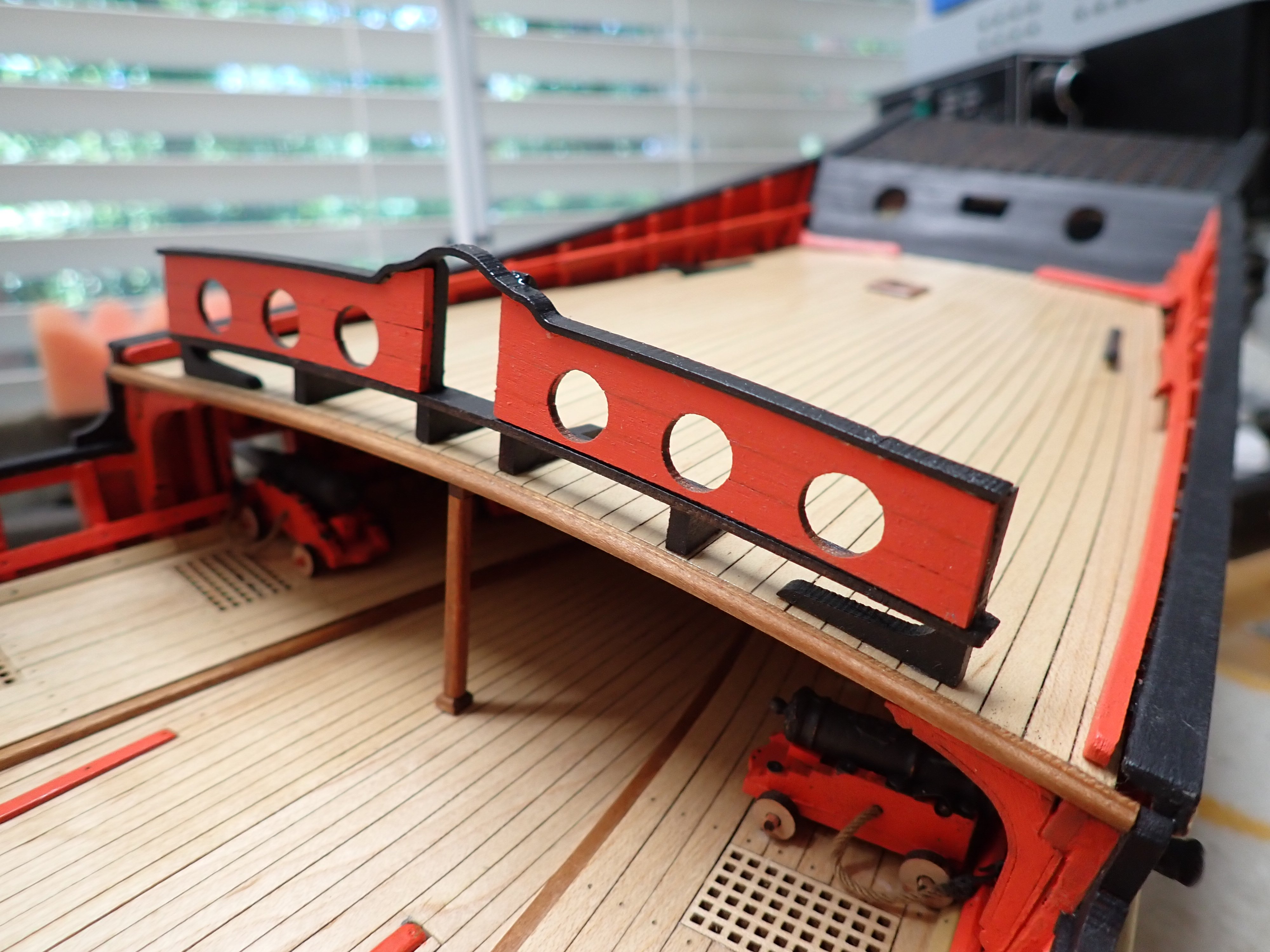
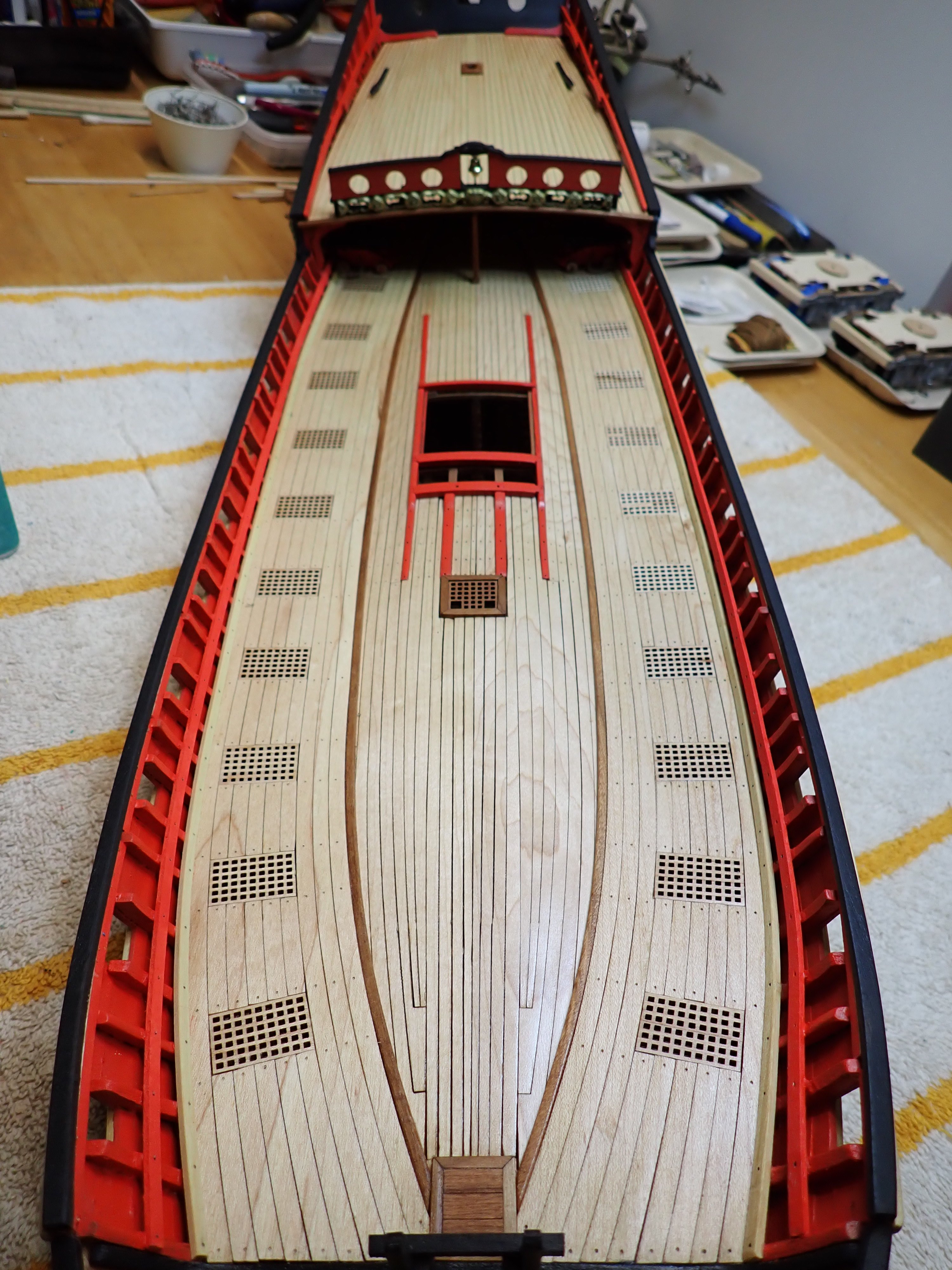
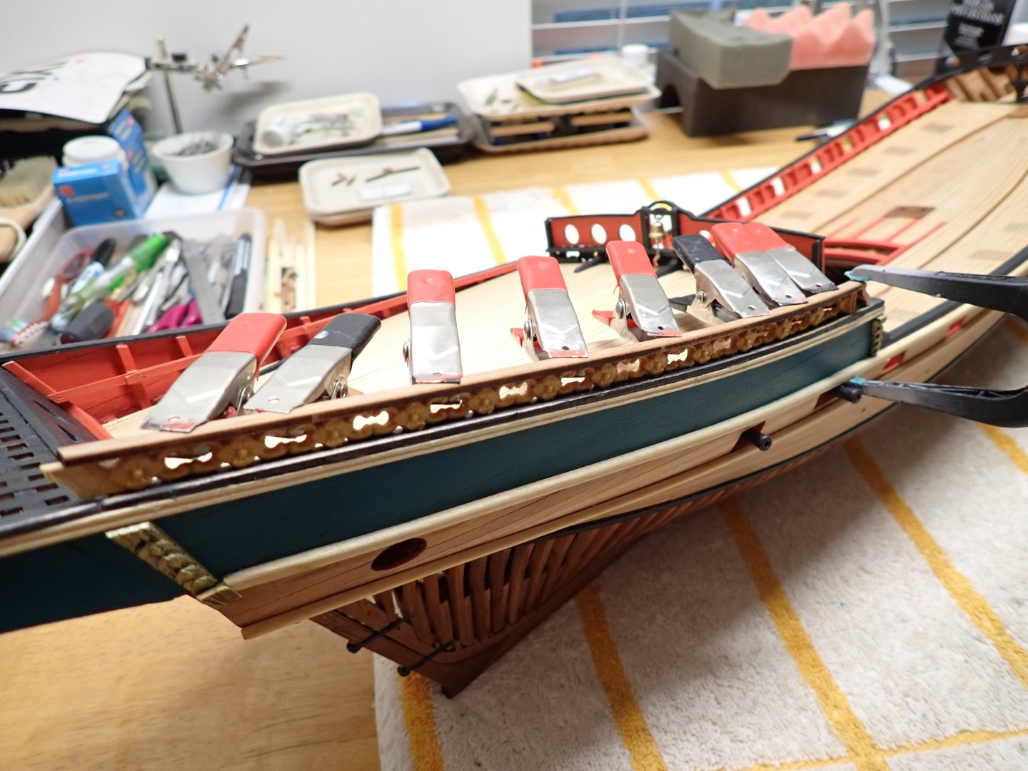
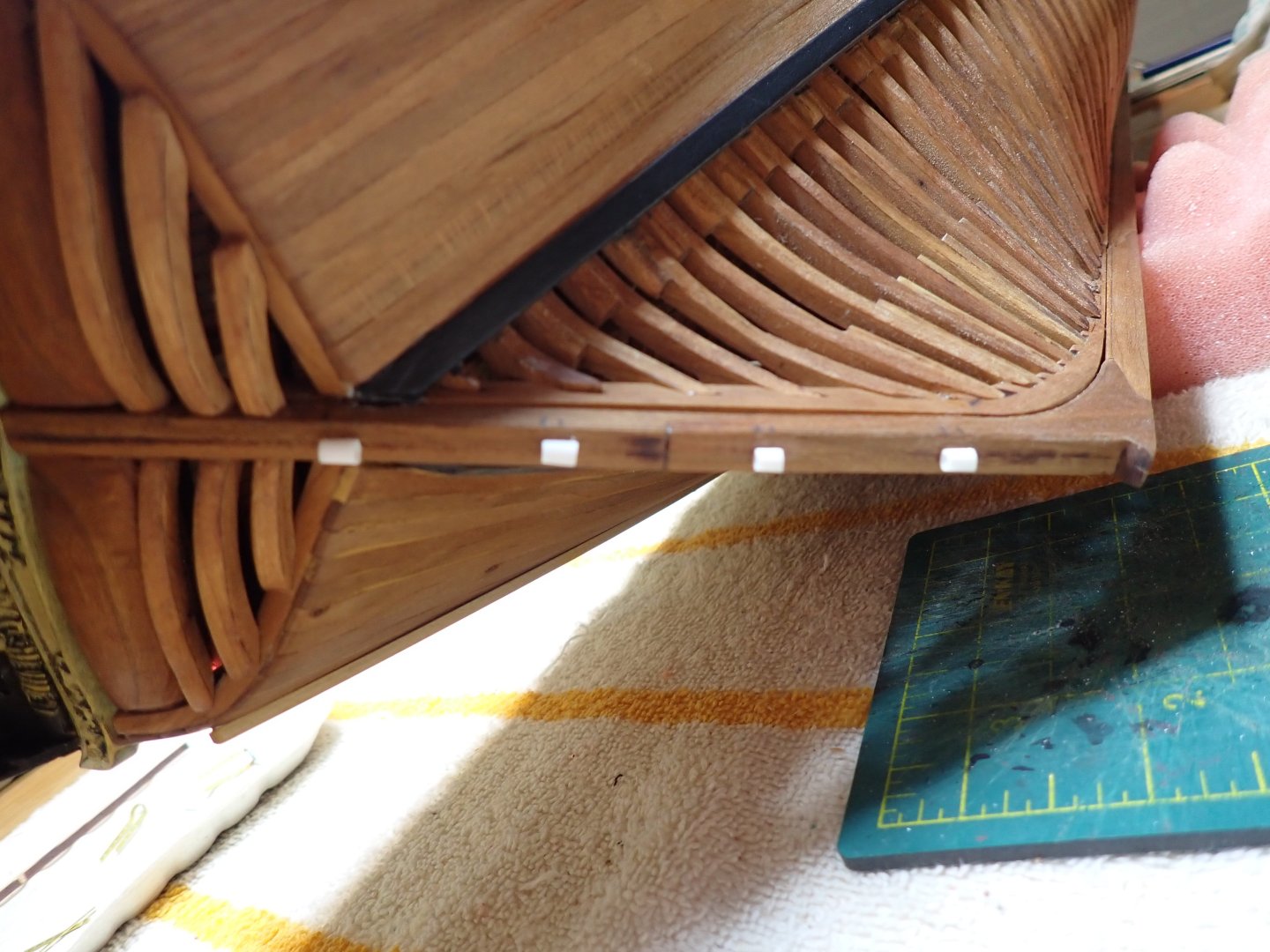
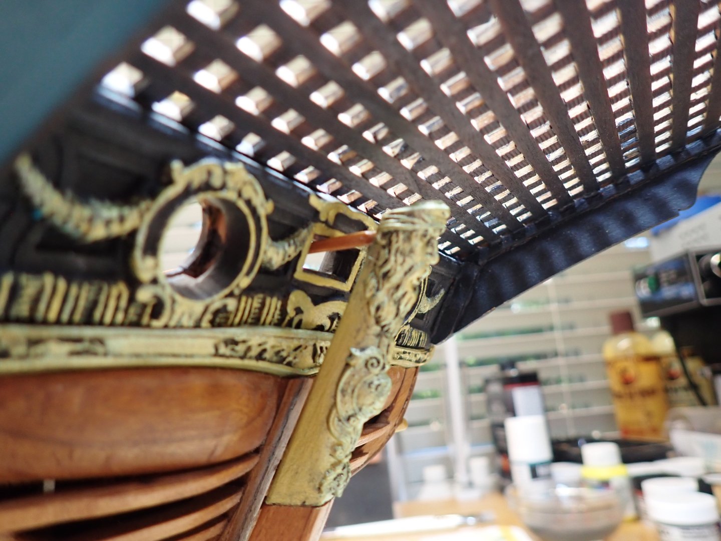
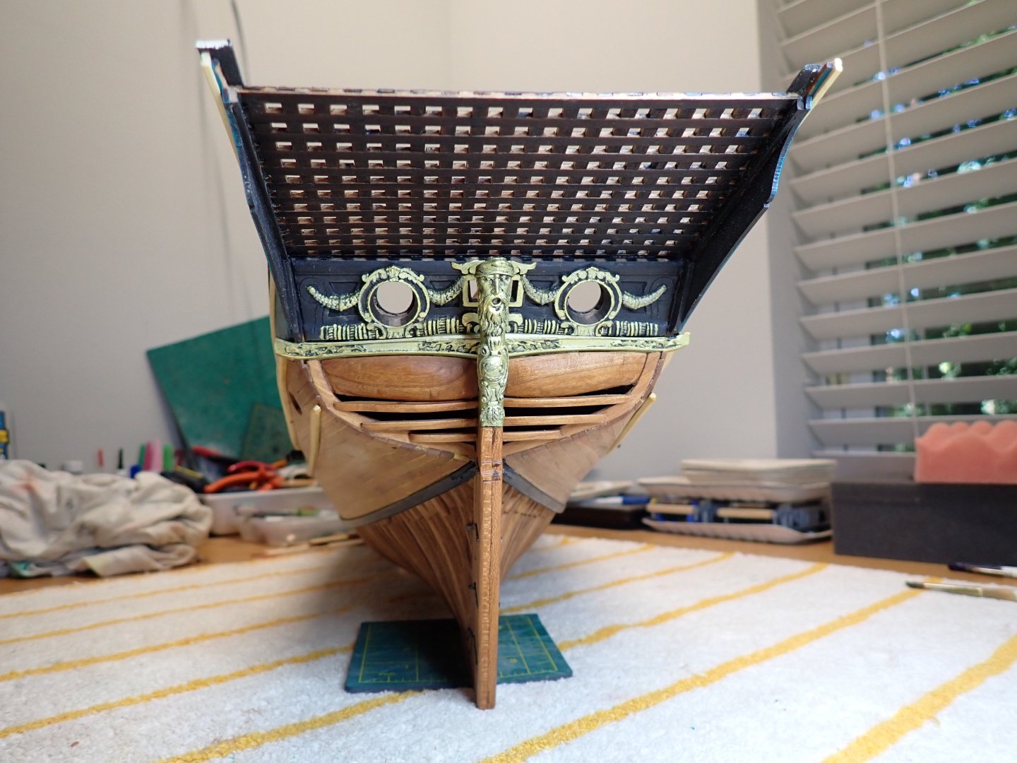
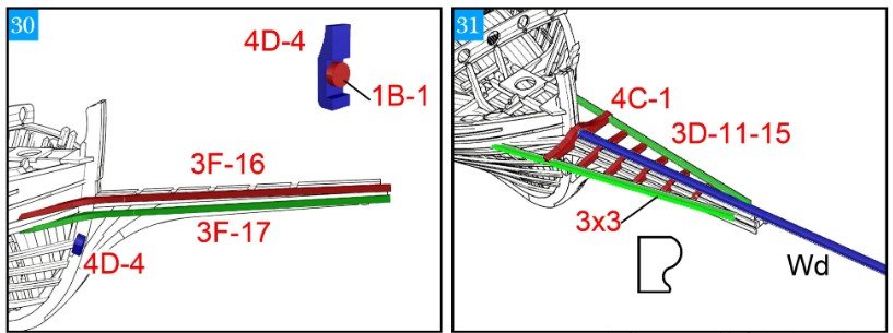
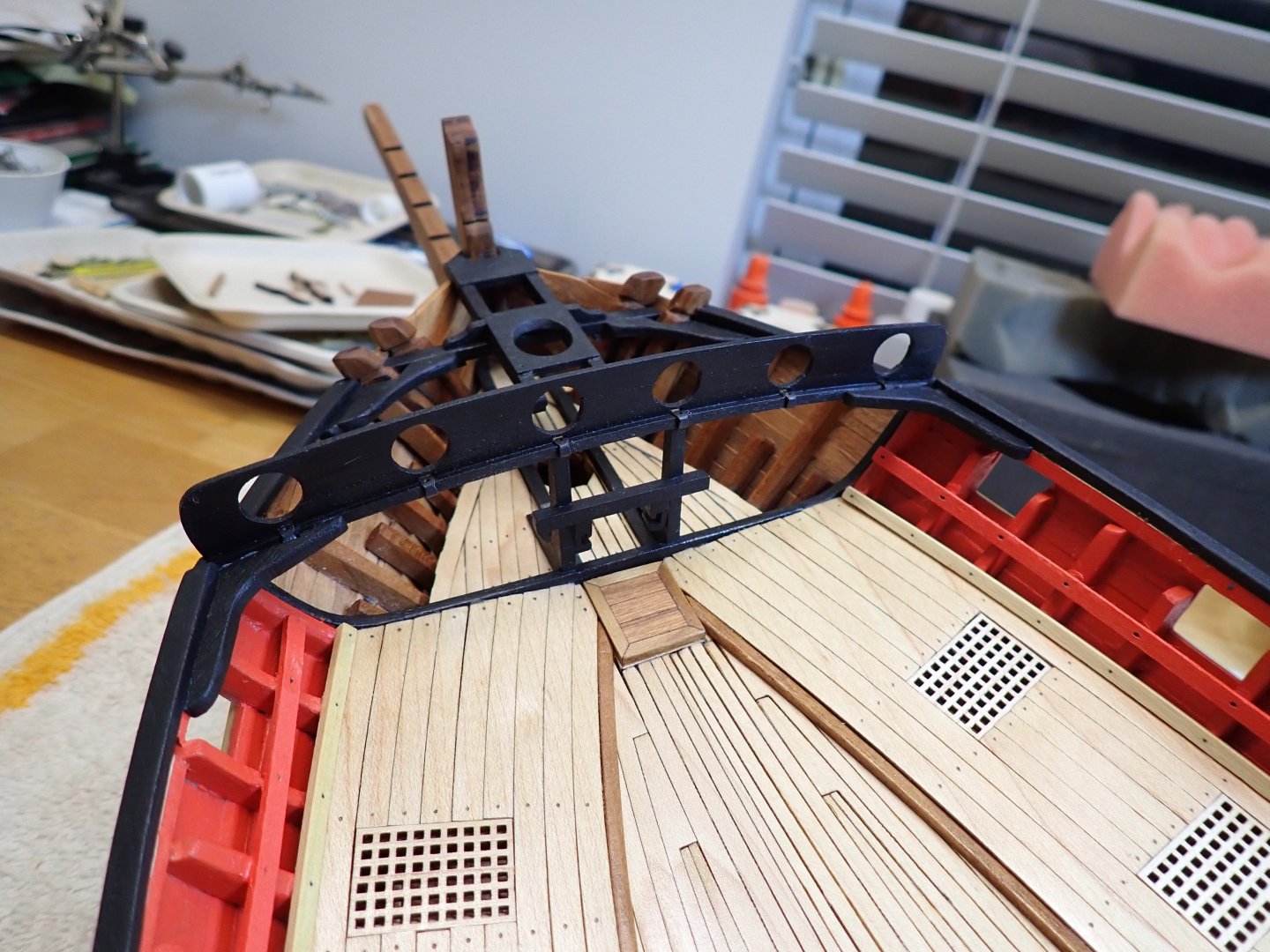
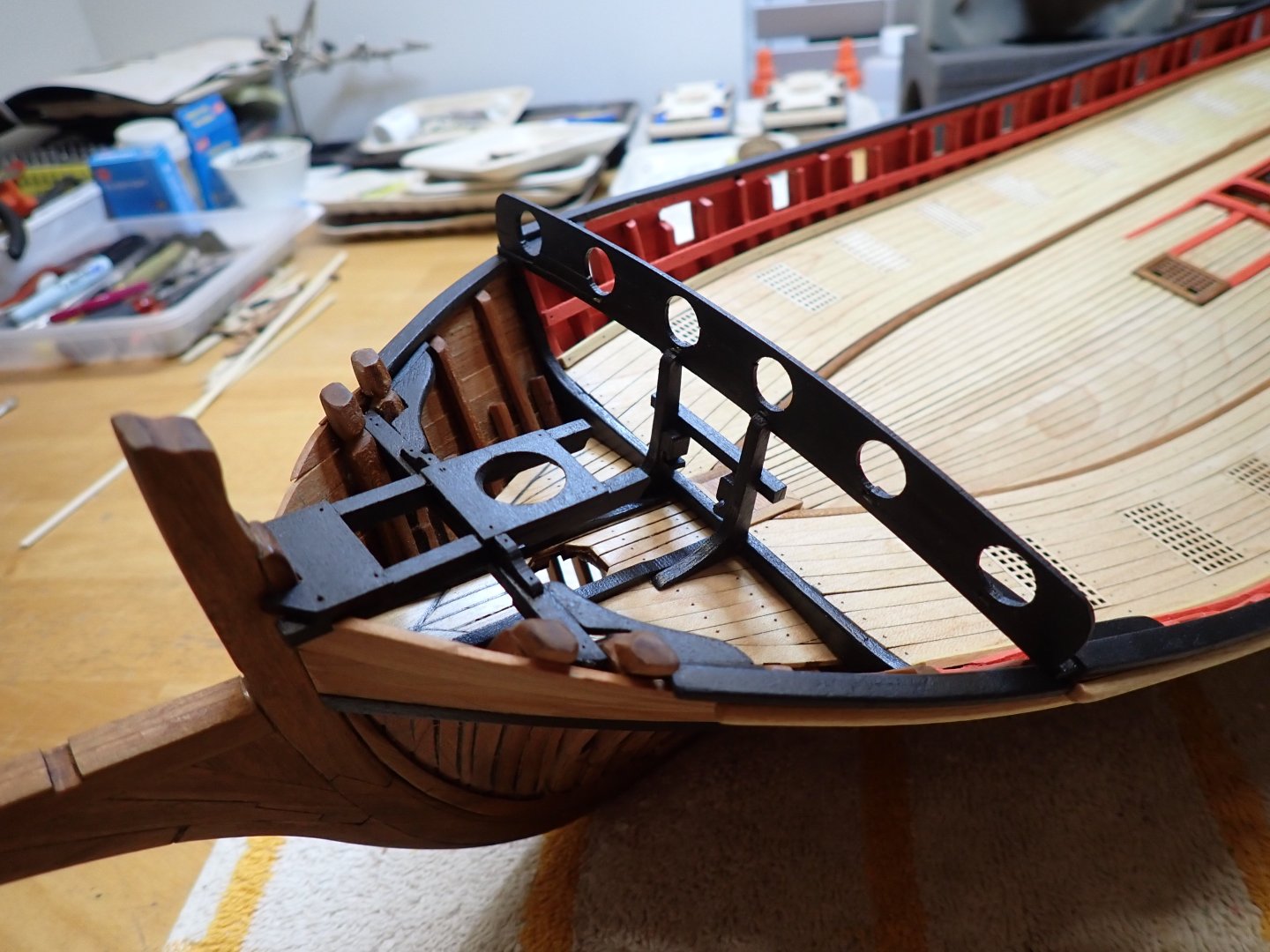
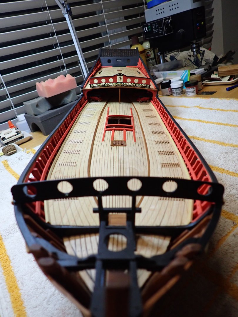
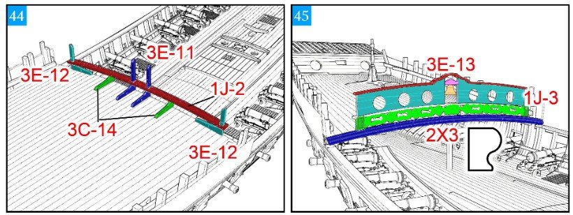
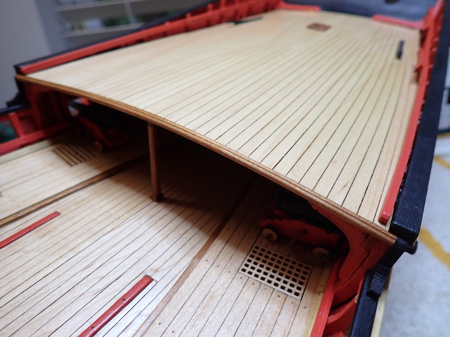
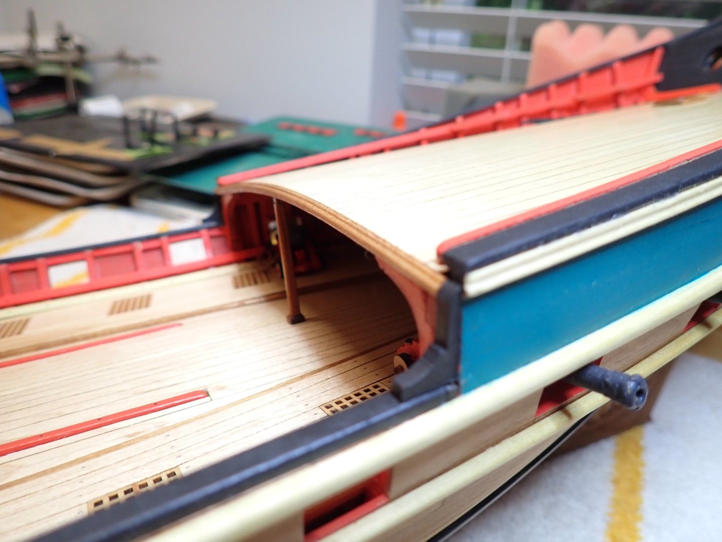
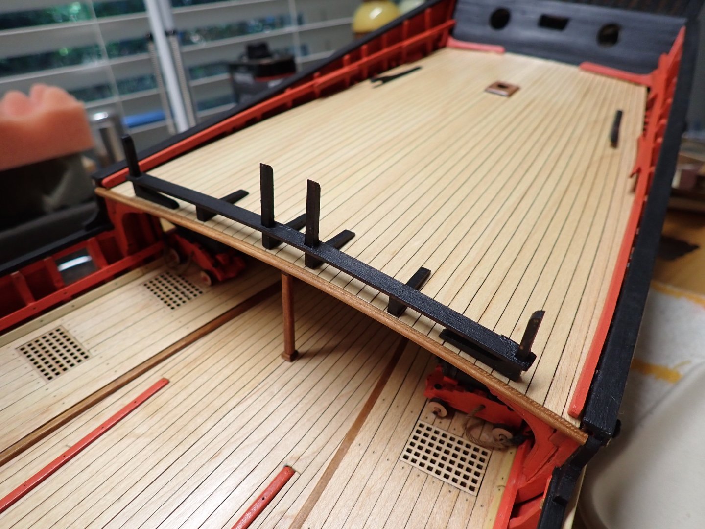
A few progress on the rear quarter deck. Rather delicate assembly due to the dry and thin wood: The first step is to glue the decorative railing in the front of the planking. 2 x 3 mm soaked in alcohol and left bending on a jig: Installation of the stiffeners under the deck: Following the instructions.... all parts are pre-painted, of course: A little bell to attract the attention of the crew: The kit does not provide the end pieces of the freeze. I will have to think about something..... Overall view: Yves


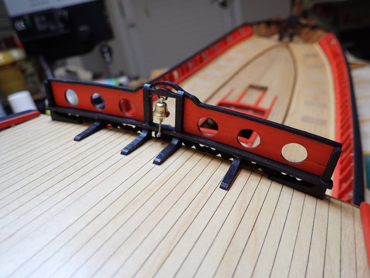

- 185 replies
-
- 17
-
-
-
Excellent choice. That should make a fantastic model, at the scale of 1/12. Yves
-
I have this kit in my stash and will watch your progress with interest. Yves
-
Chuck, I love your new workplace but mostly the Bally Old chicago pinball machine, in the corner. It is one of my coveted machines, as I already own a Bally Mata Hari, Playboy, Silverball, Xenon and Medusa plus a Spanish machine from Recel. Yves