yvesvidal
-
Posts
3,641 -
Joined
-
Last visited
Content Type
Profiles
Forums
Gallery
Events
Everything posted by yvesvidal
-
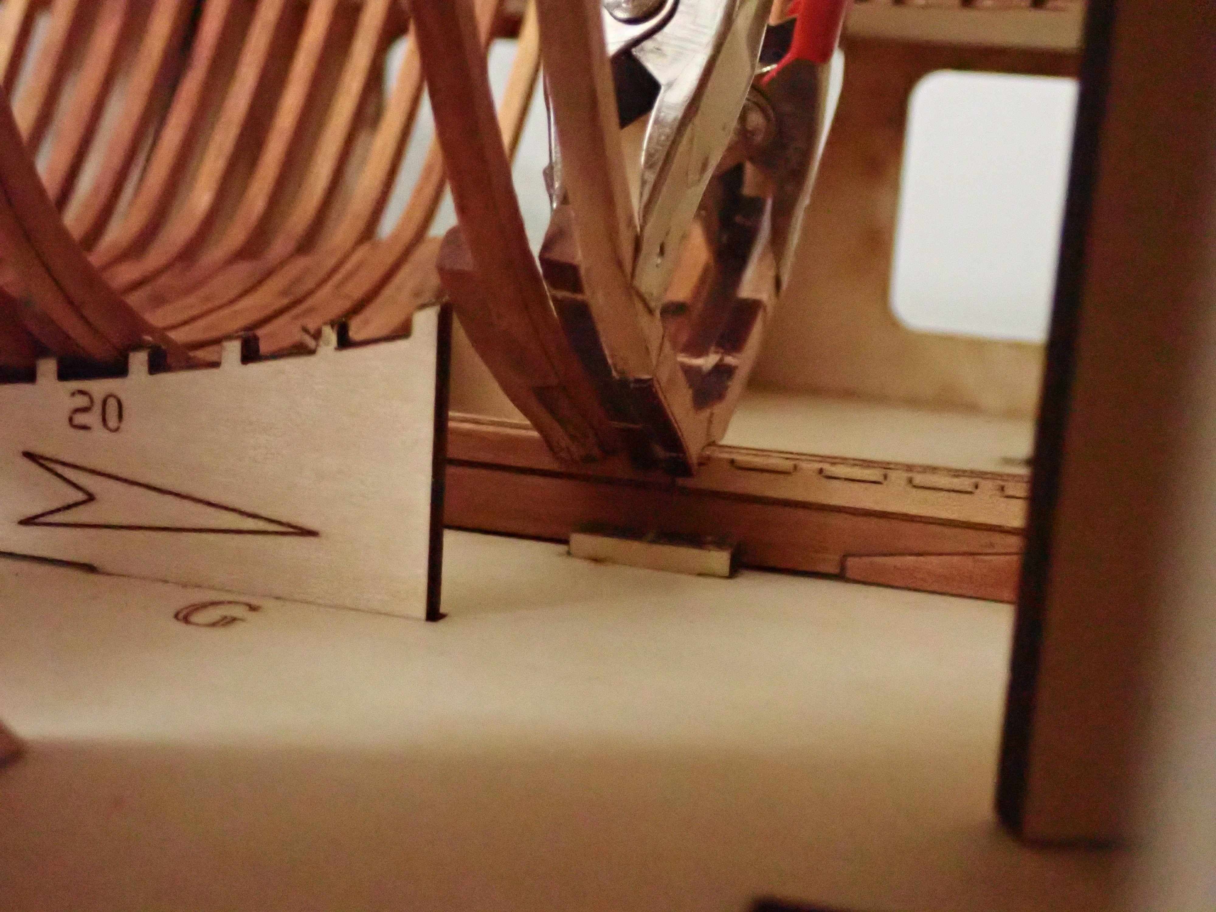
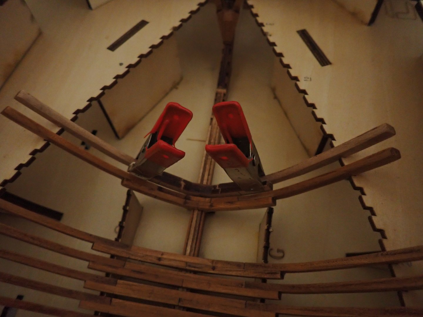
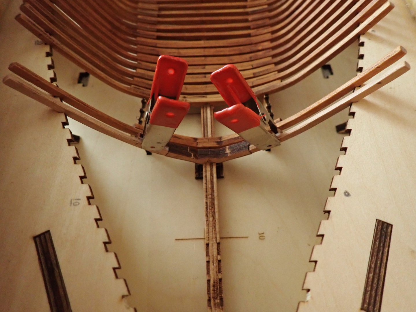
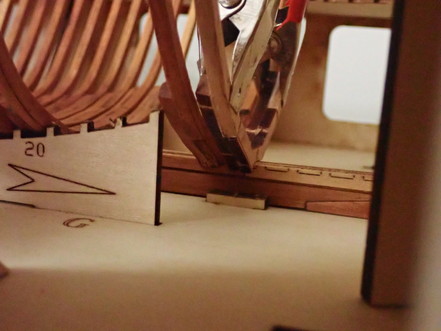
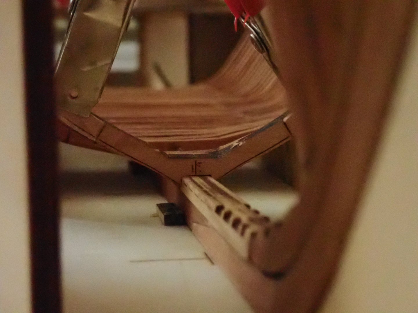
 Nice and more realistic change to the kit. I do not understand why they would have designed the kit in this way. The keel may be very subtle on a Riva, but it does exist no matter what. Other thing: Amati shows these horrible staples/nails to hold the planks.... The real RIVA is assembled using clamps, as shown on the picture. Yves
- 6 replies
-
- 2
-

-
- runabout
- riva aquarama
- (and 1 more)
-
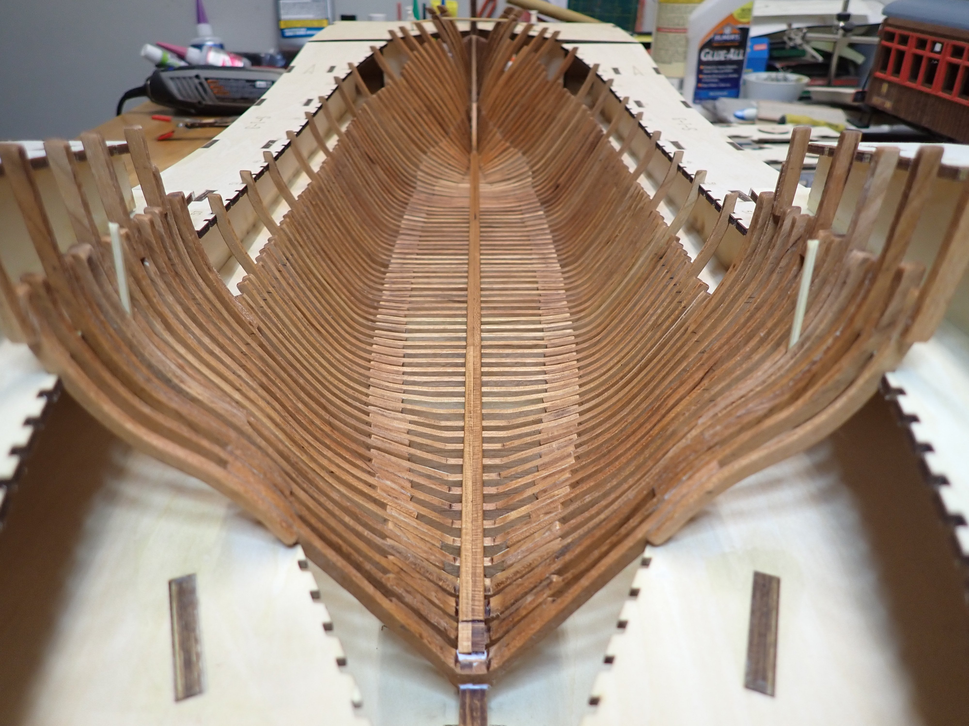
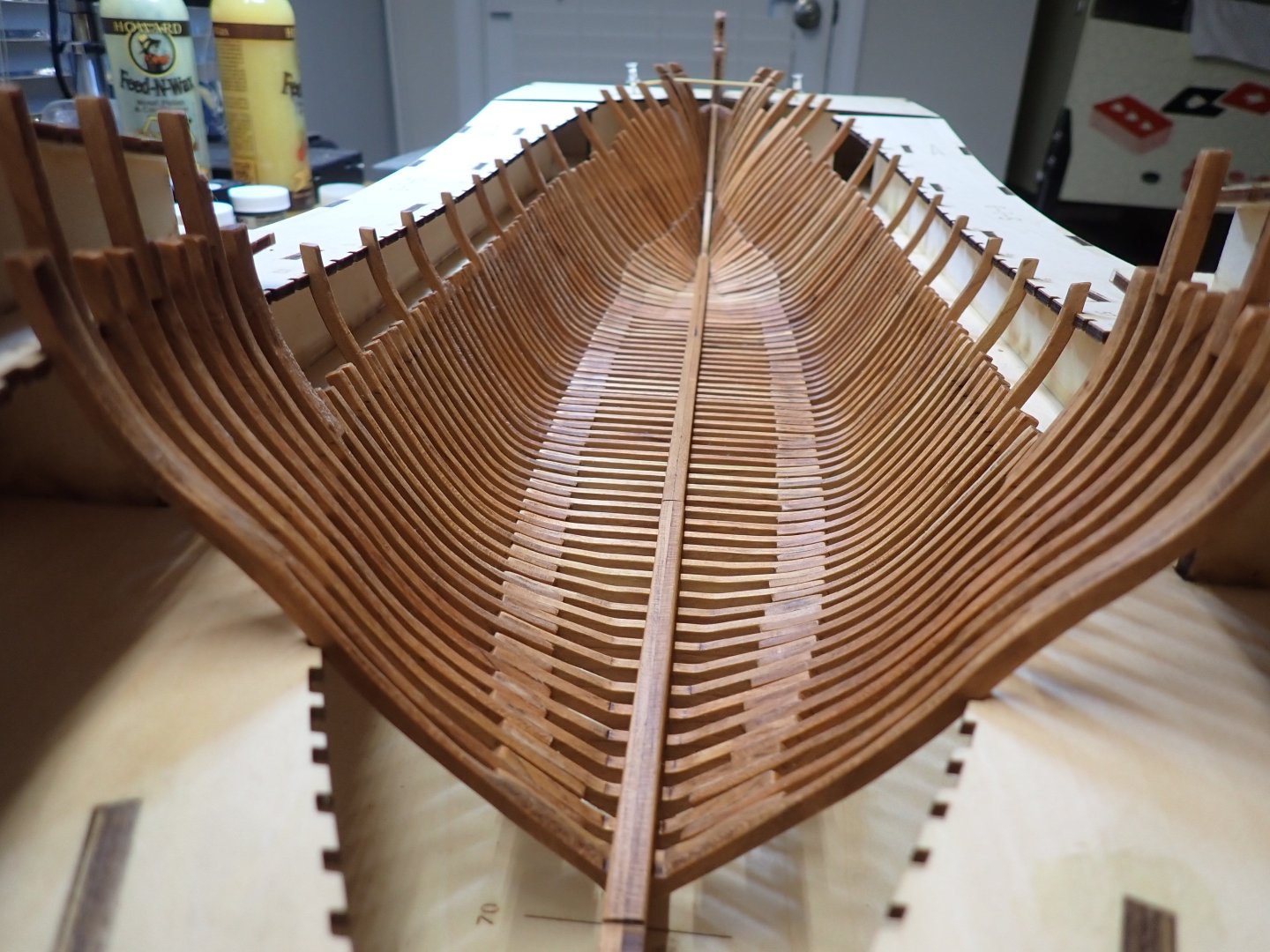
I finalized Frames #71, 72 and 73. These have been glued and a segment of keelson installed to keep everything in place: And the usual perspective pictures: I am working on the #80's frames which are really delicate and require a ton of adjustment to fit correctly. By far, the most difficult part of the hull. Yves

- 185 replies
-
- 21
-
-

-
Incredible model and assembly. You are turning this Plastic kit into a little marvel: Pimping it up, should I say ! I remember assembling the Heller Royal Louis some fifty years ago, but it was far from your level of expertise. Looking at the stern of that vessel, one can see the differences of richness and decorations between the French and British vessels. The French builders were definitely putting more emphasis into the glamor and opulence. That "Chateau Arriere" is absolutely amazing. Yves
- 44 replies
-
- 1
-
-
- soleil royal
- Heller
- (and 5 more)
-
Very nice standing rigging. Masts are perfectly straight. Great job. Yves
-
WOW, what a little marvel you have done. I really enjoy the shapes of the hull and the moderate height of the decks, so different from these ugly floating skyscrapers we see on our seas. Yves
- 33 replies
-
- 4
-
-
- Queen Mary 2
- Revell
- (and 3 more)
-
What a lovely ship and great model. It deserves to have the wood (or even plastic) equivalent for modelers to enjoy. Yves
-
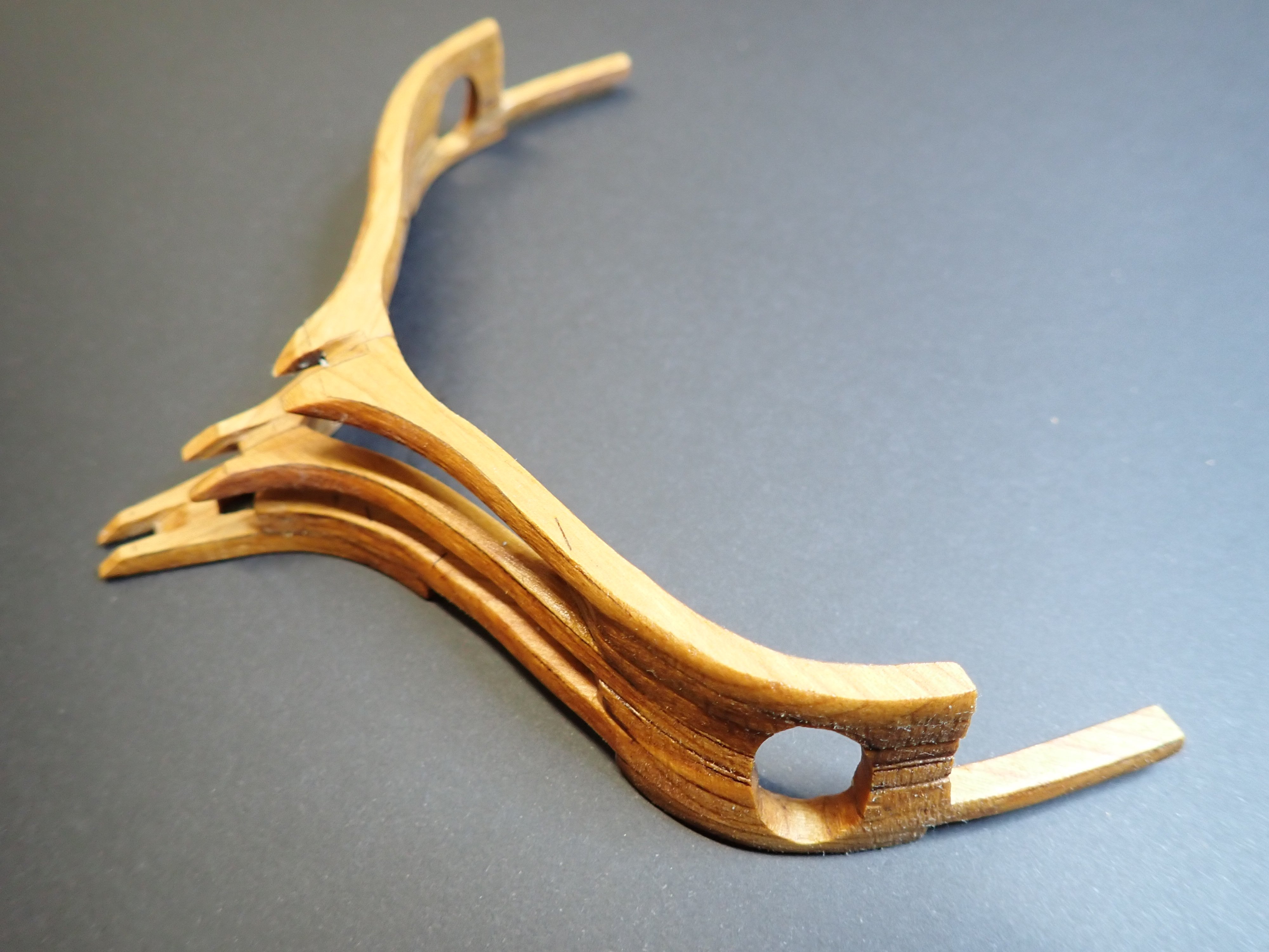
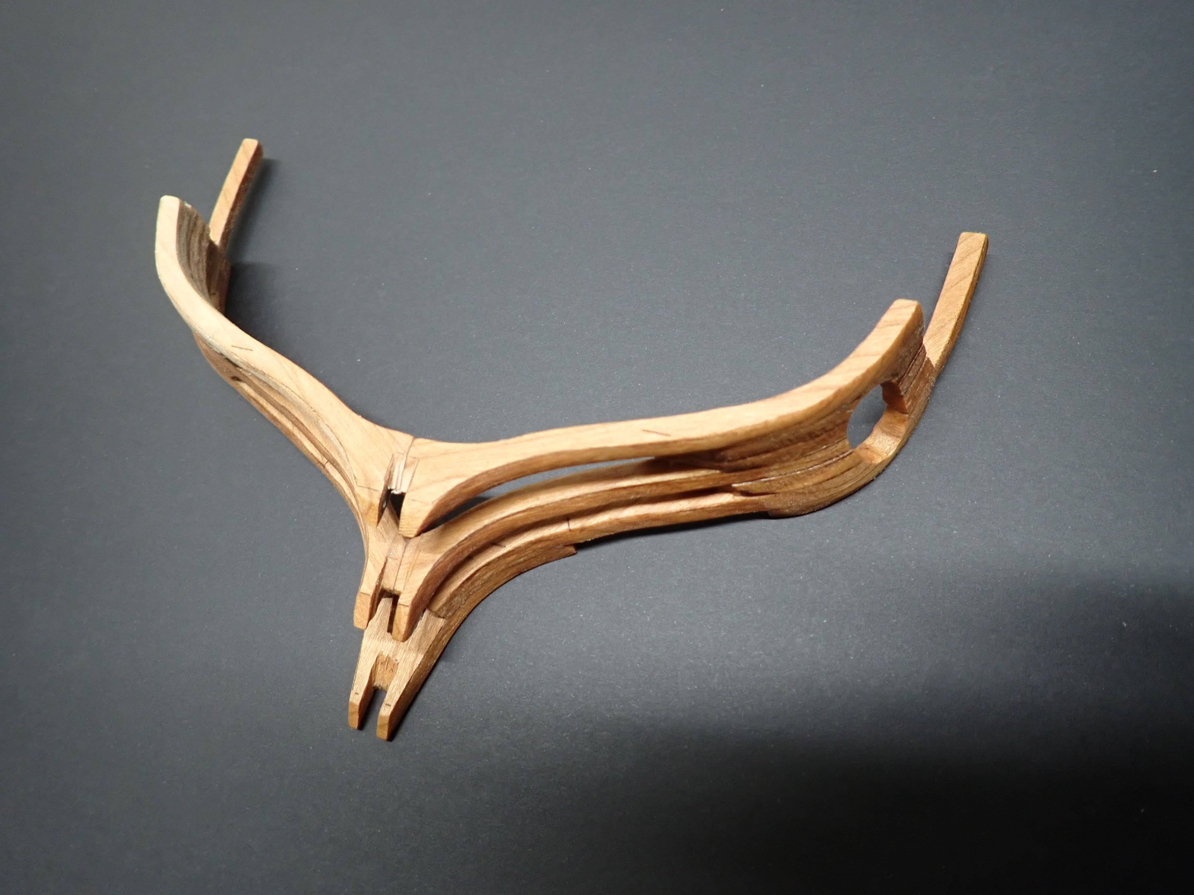
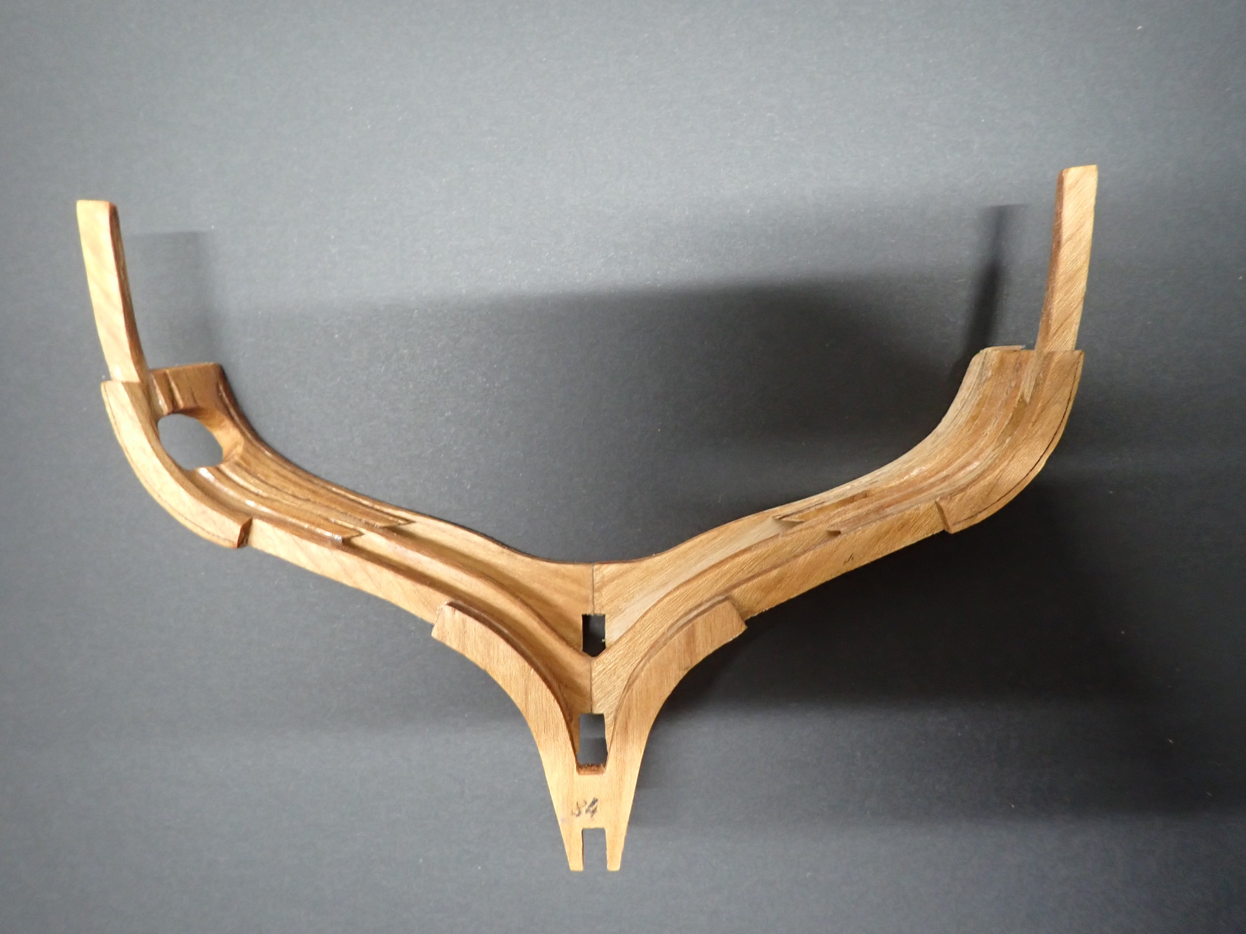
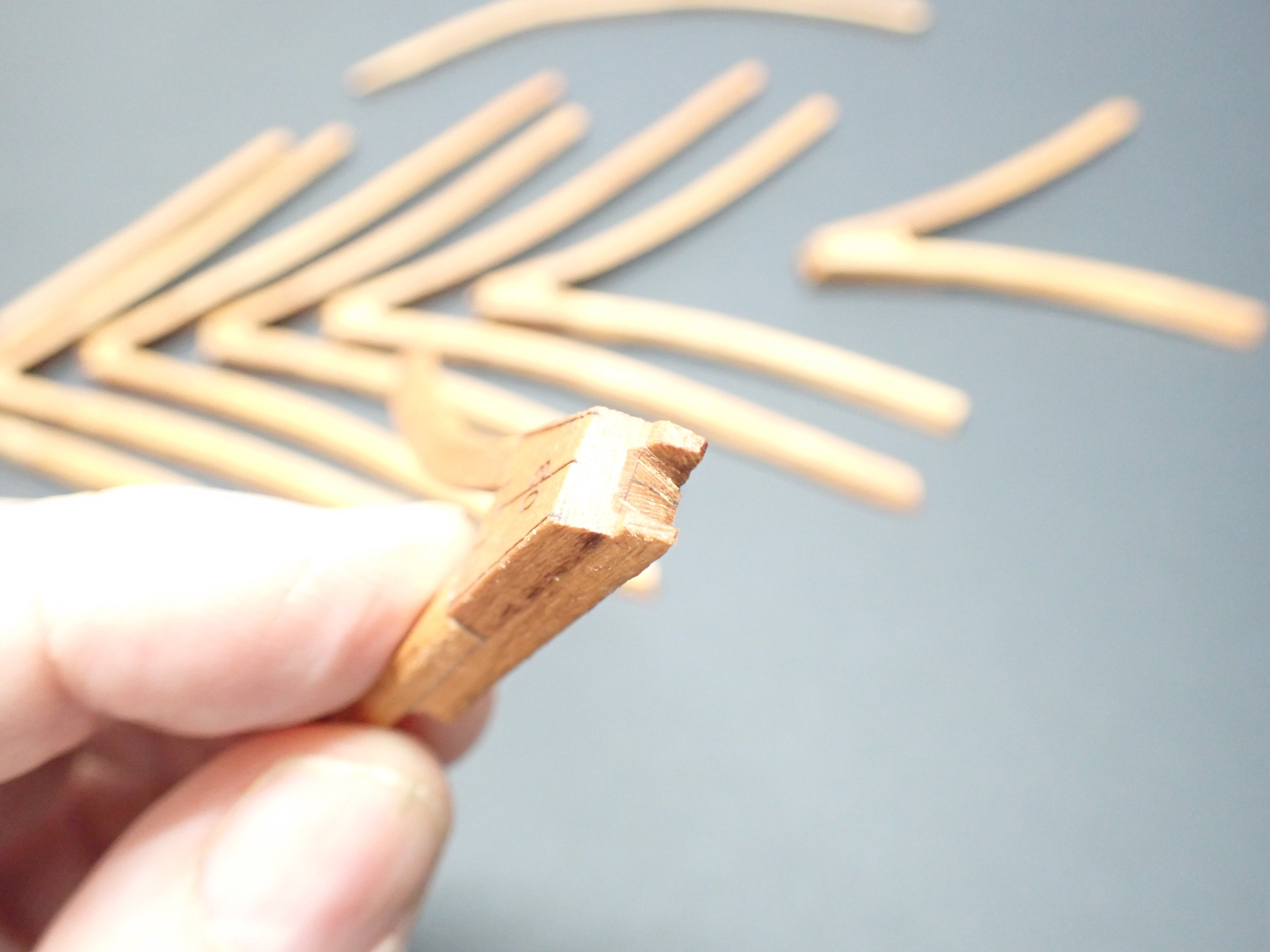
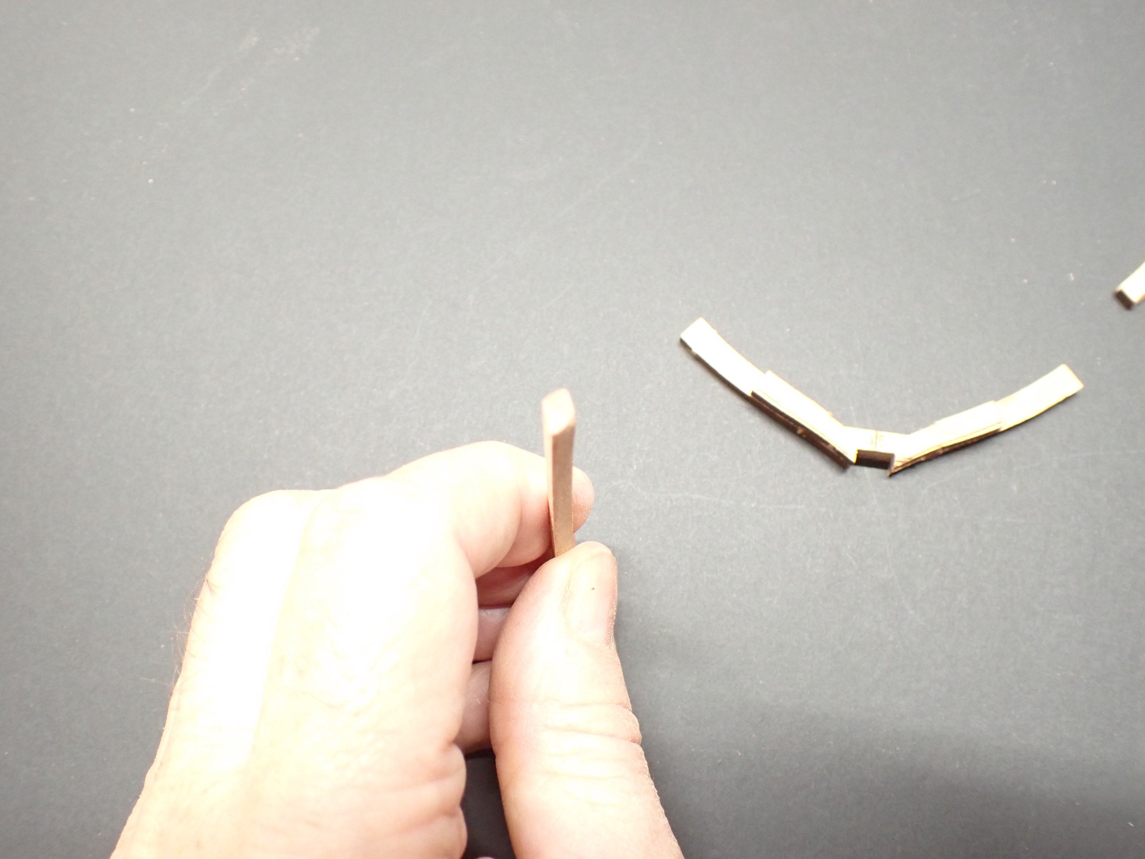
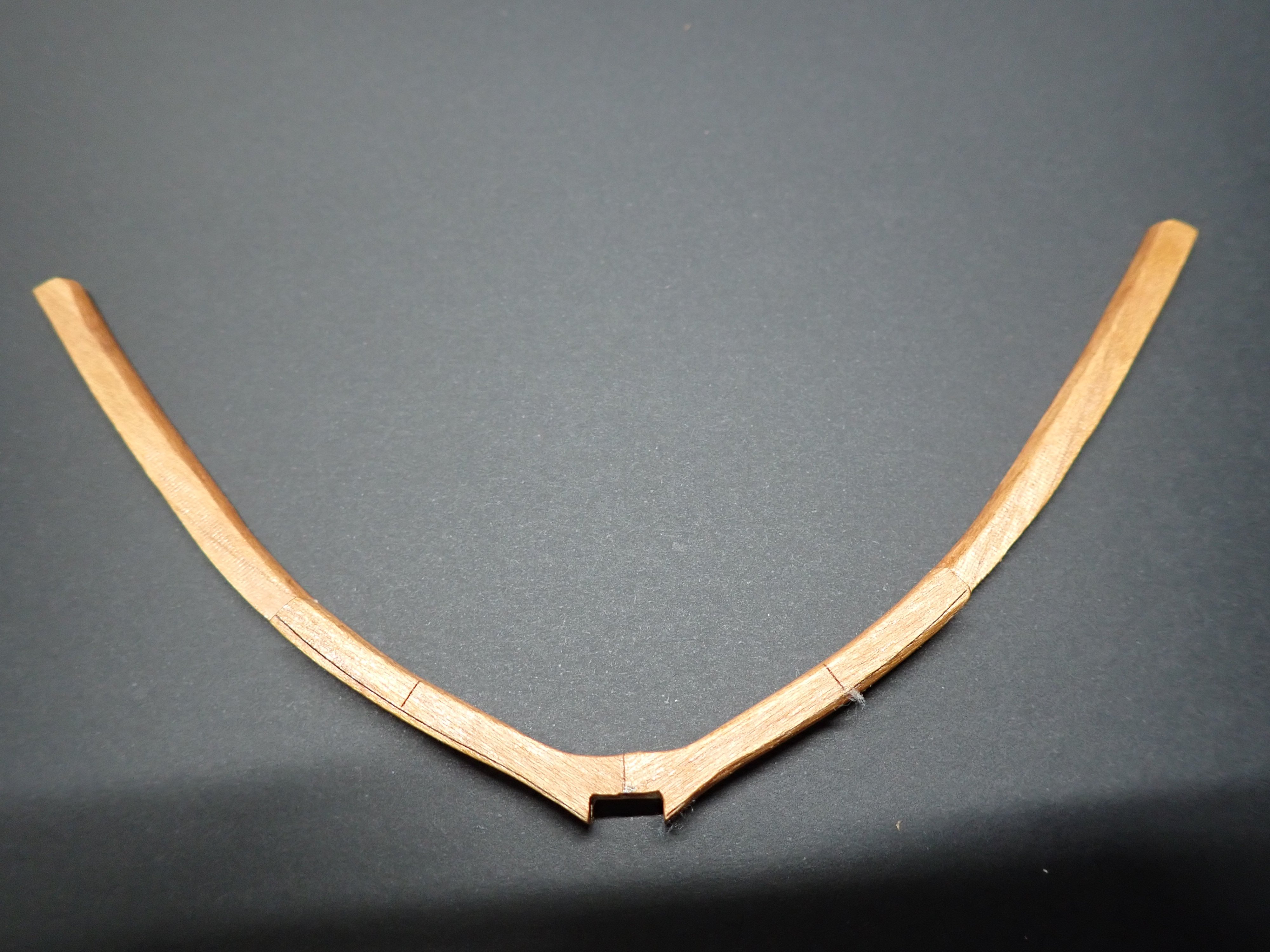
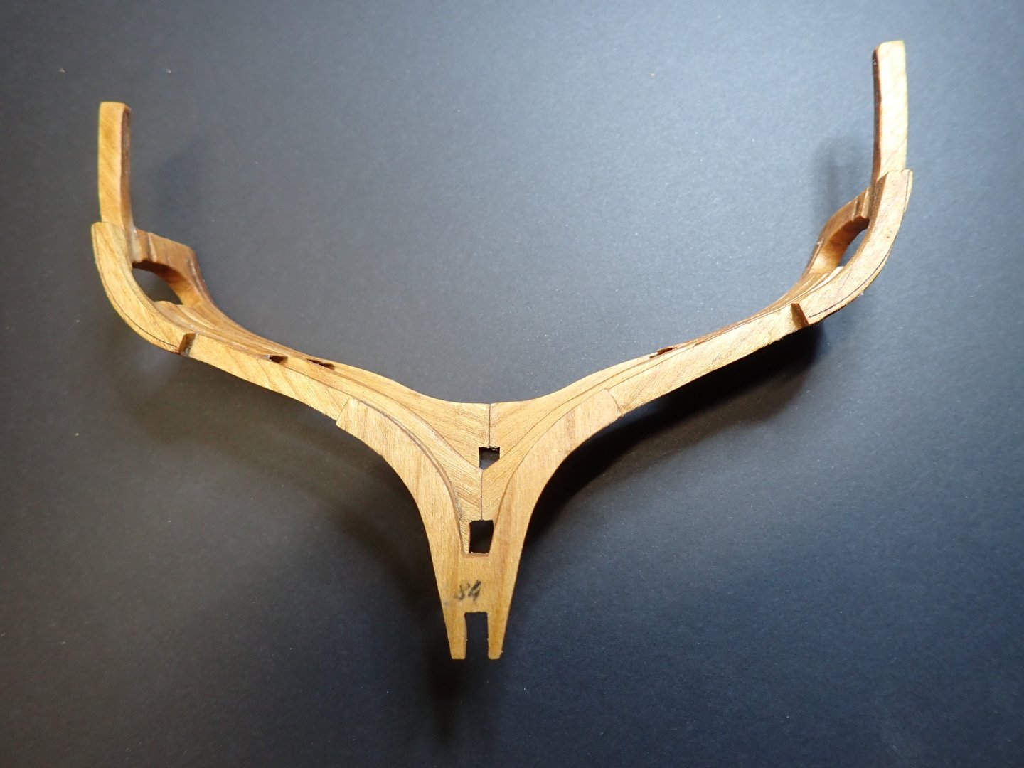
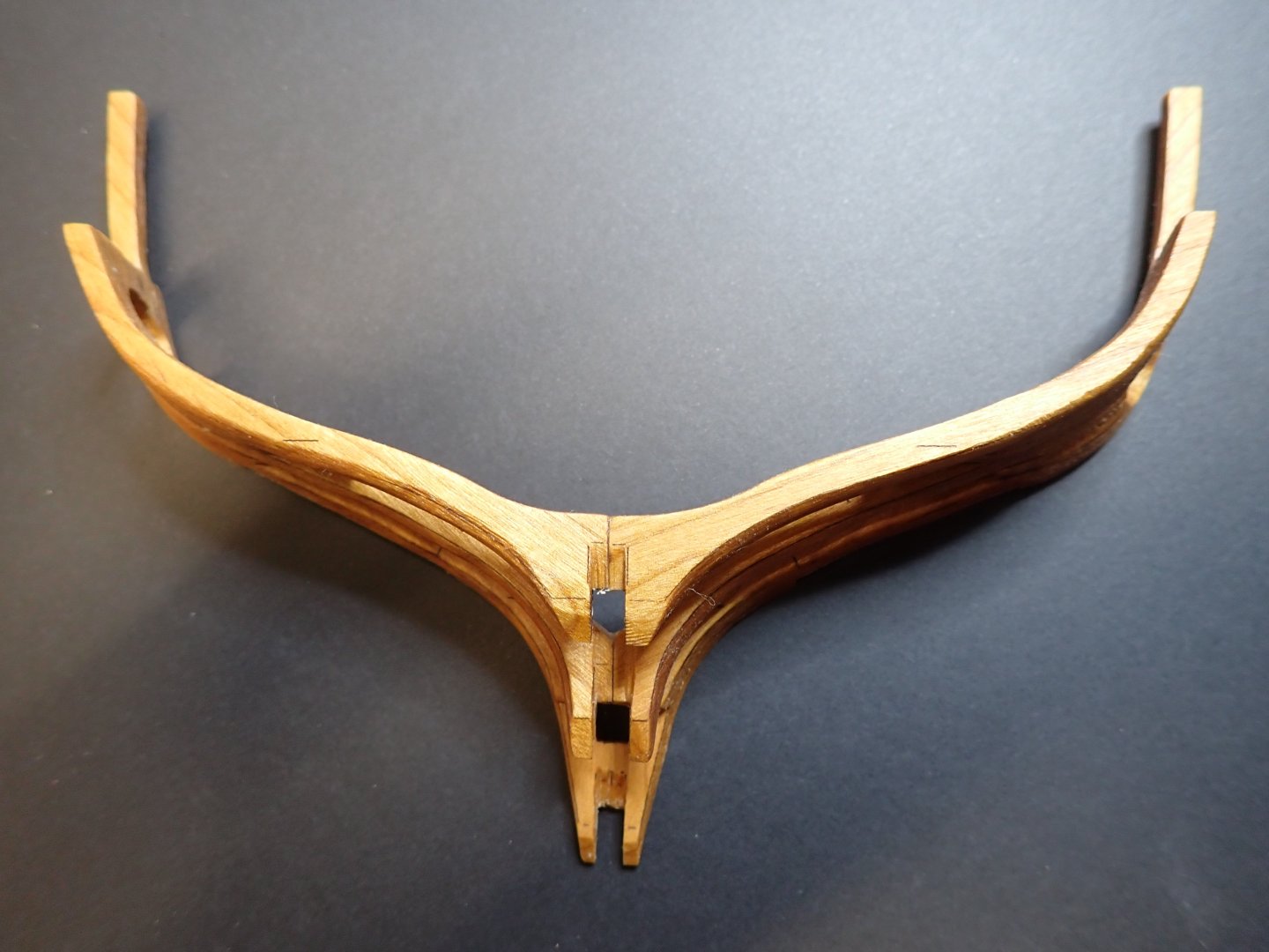
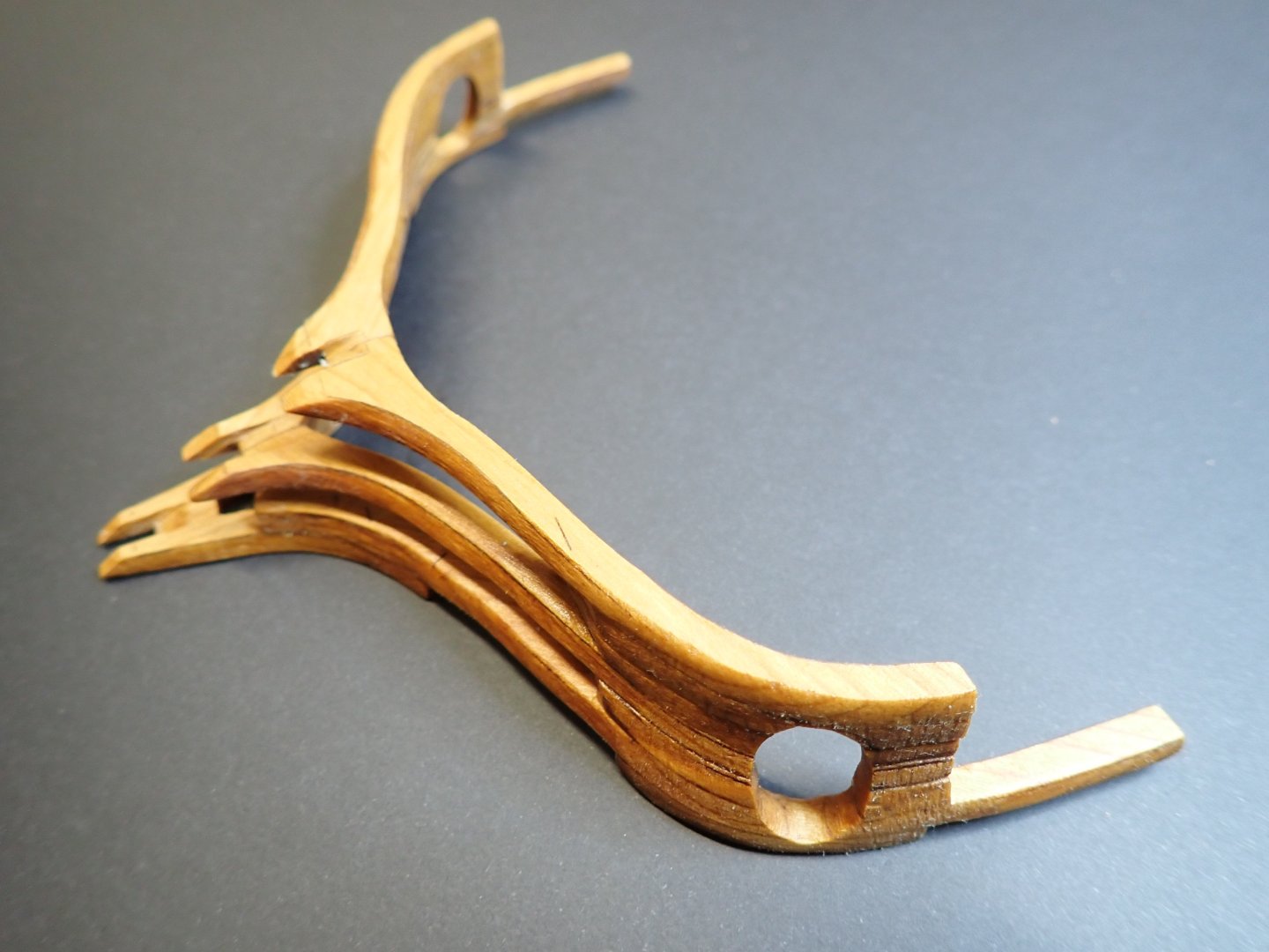
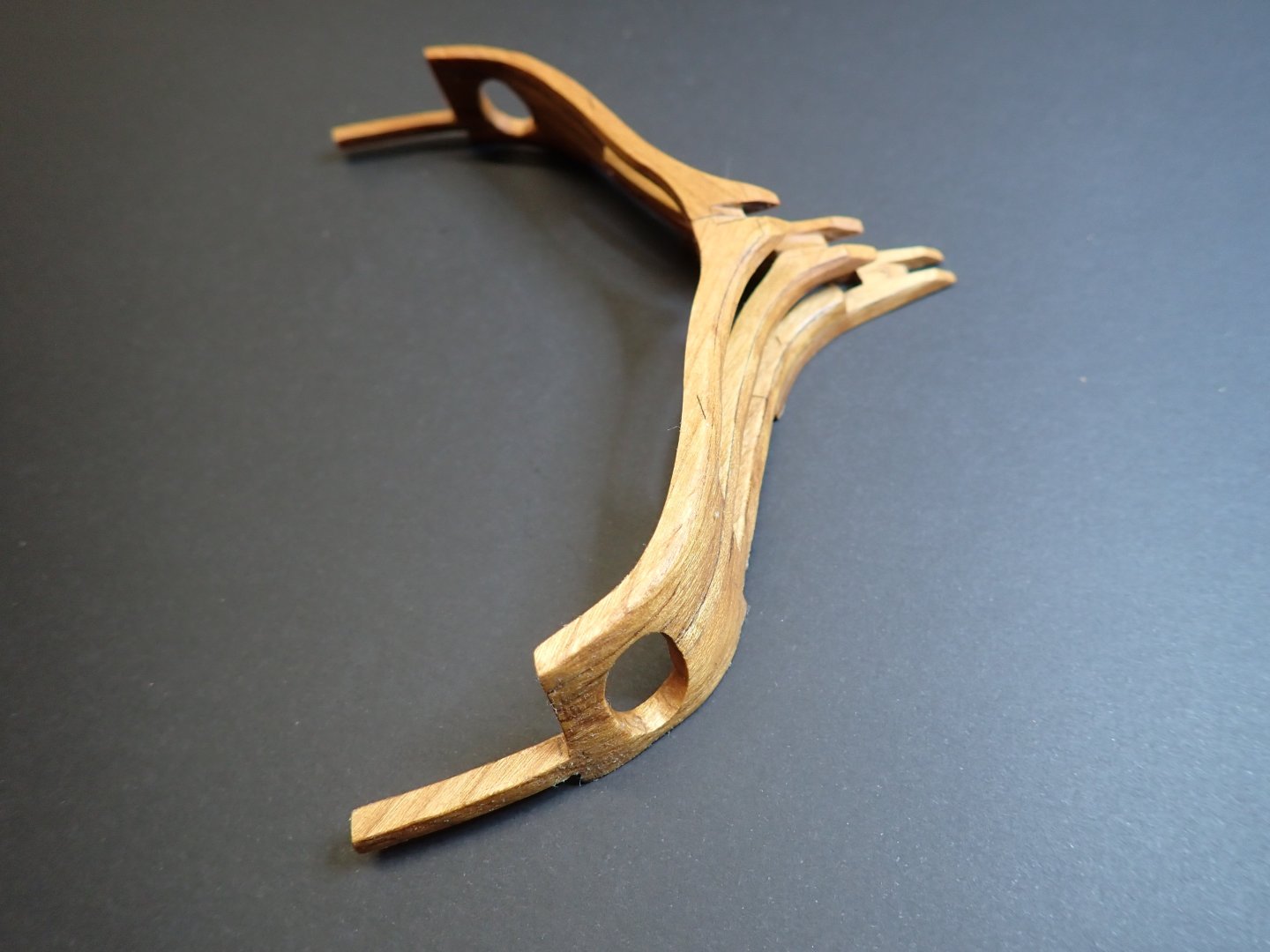
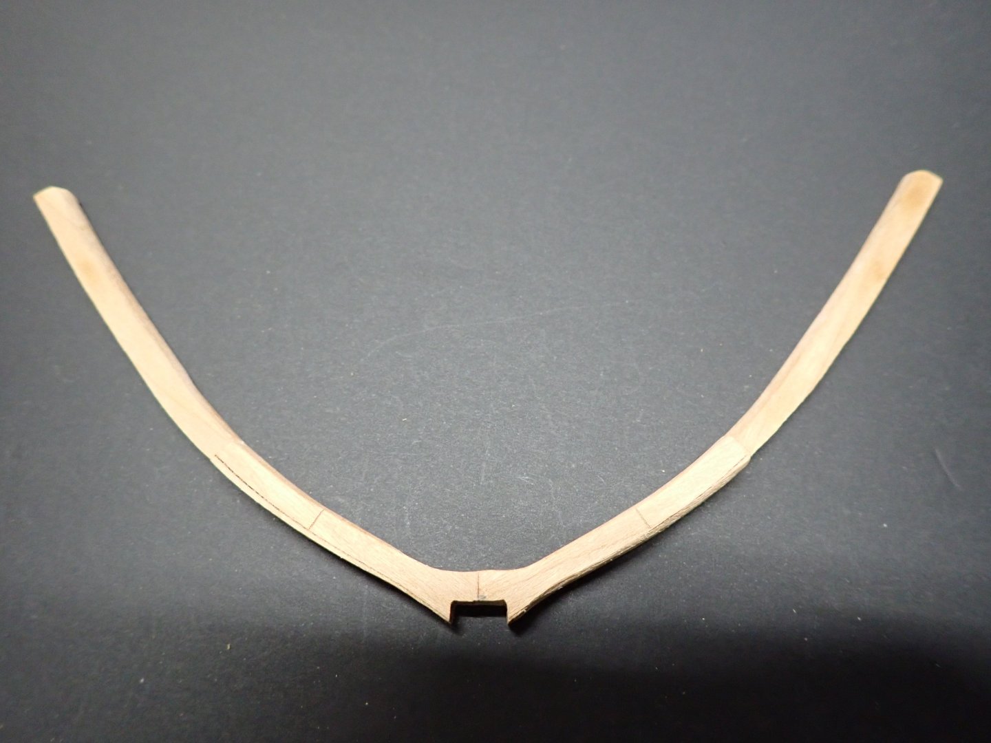
Here is the finished part: It looks like the skull of a Longhorn.... Once the oil and wax is absorbed by the wood, I will come back with fine sand paper and polish it in a smoother way. The pictures are very revealing even though the parts look good with the eyes. Yves


- 185 replies
-
- 19
-
-
-
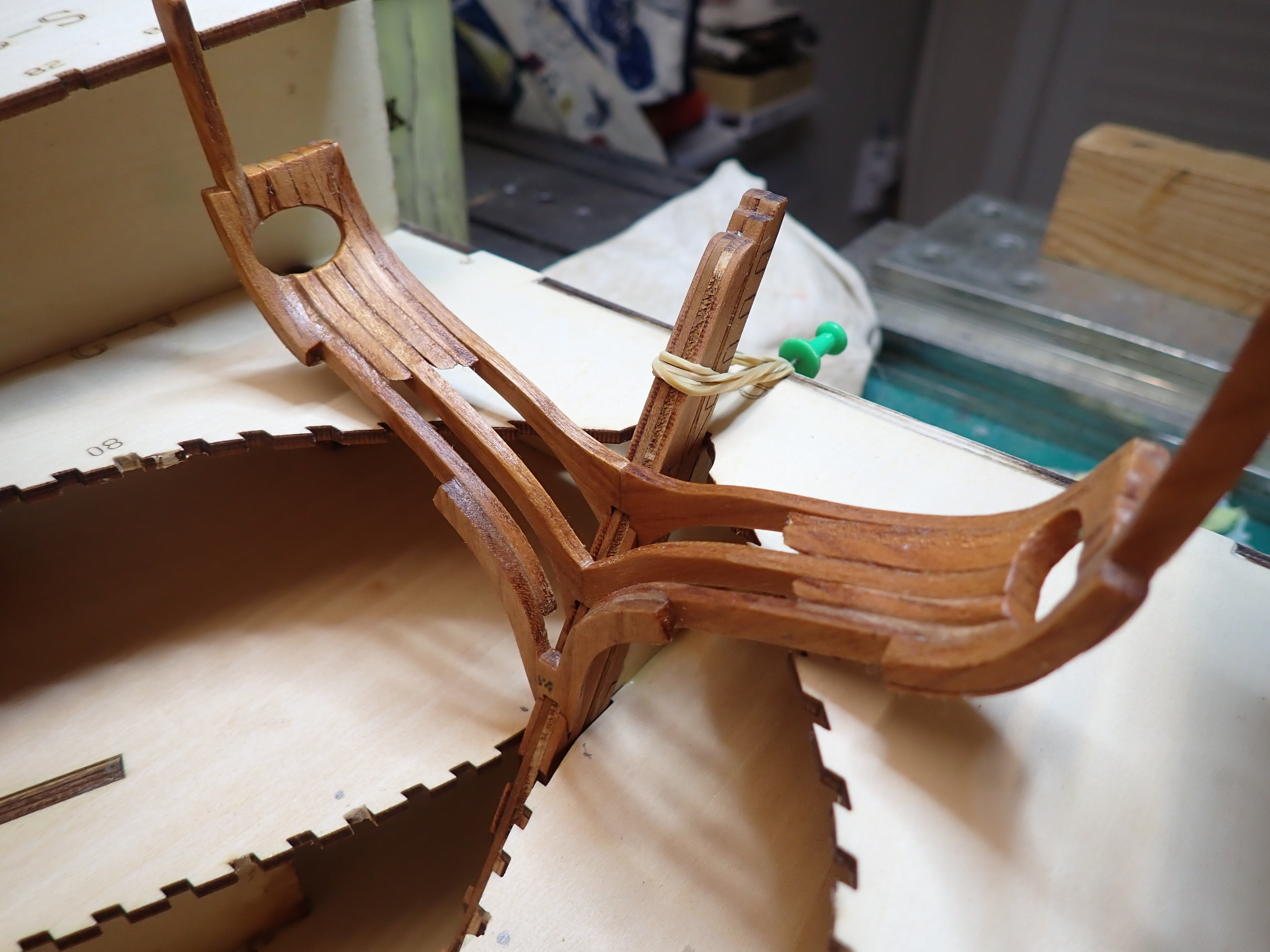
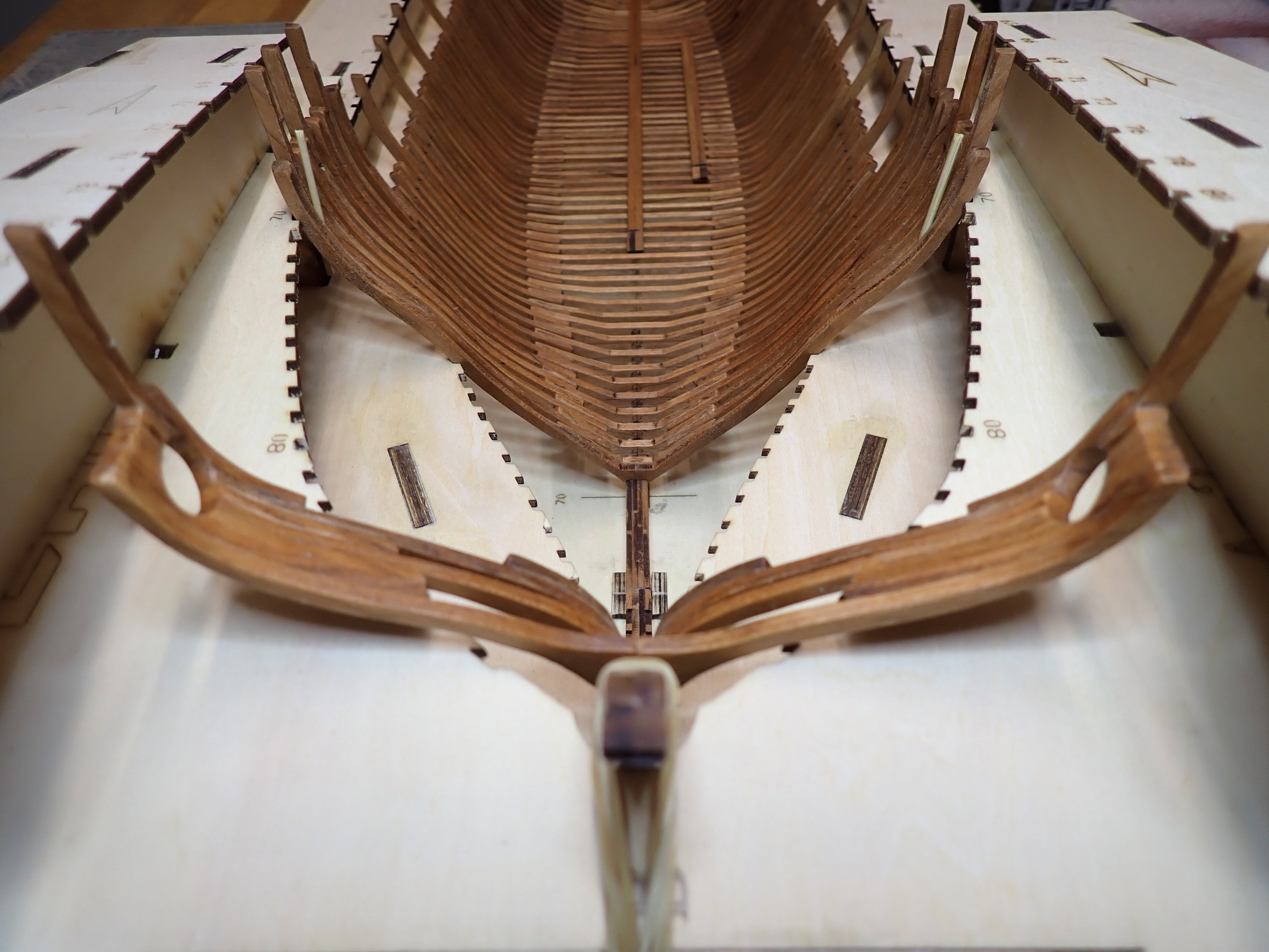
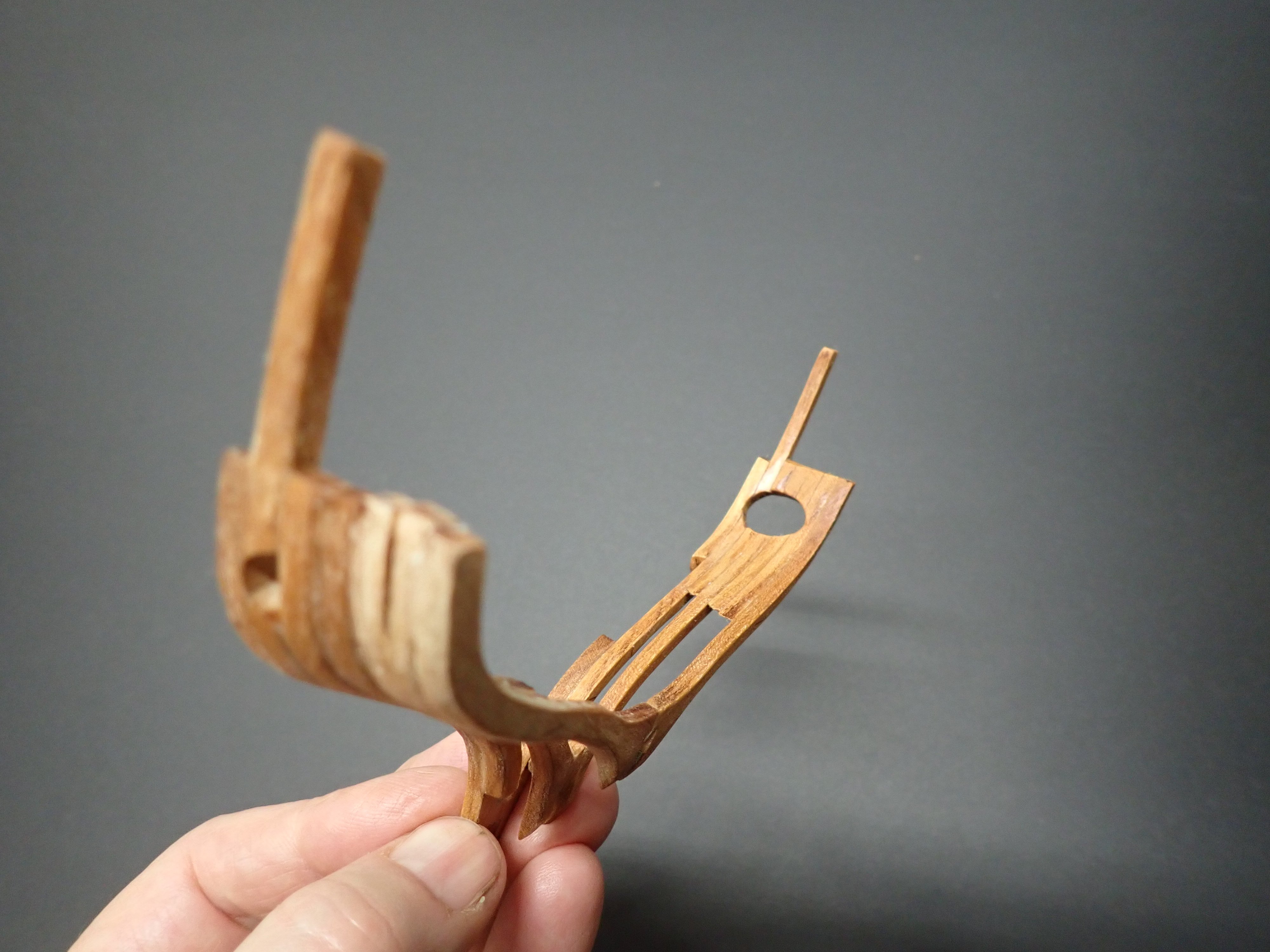
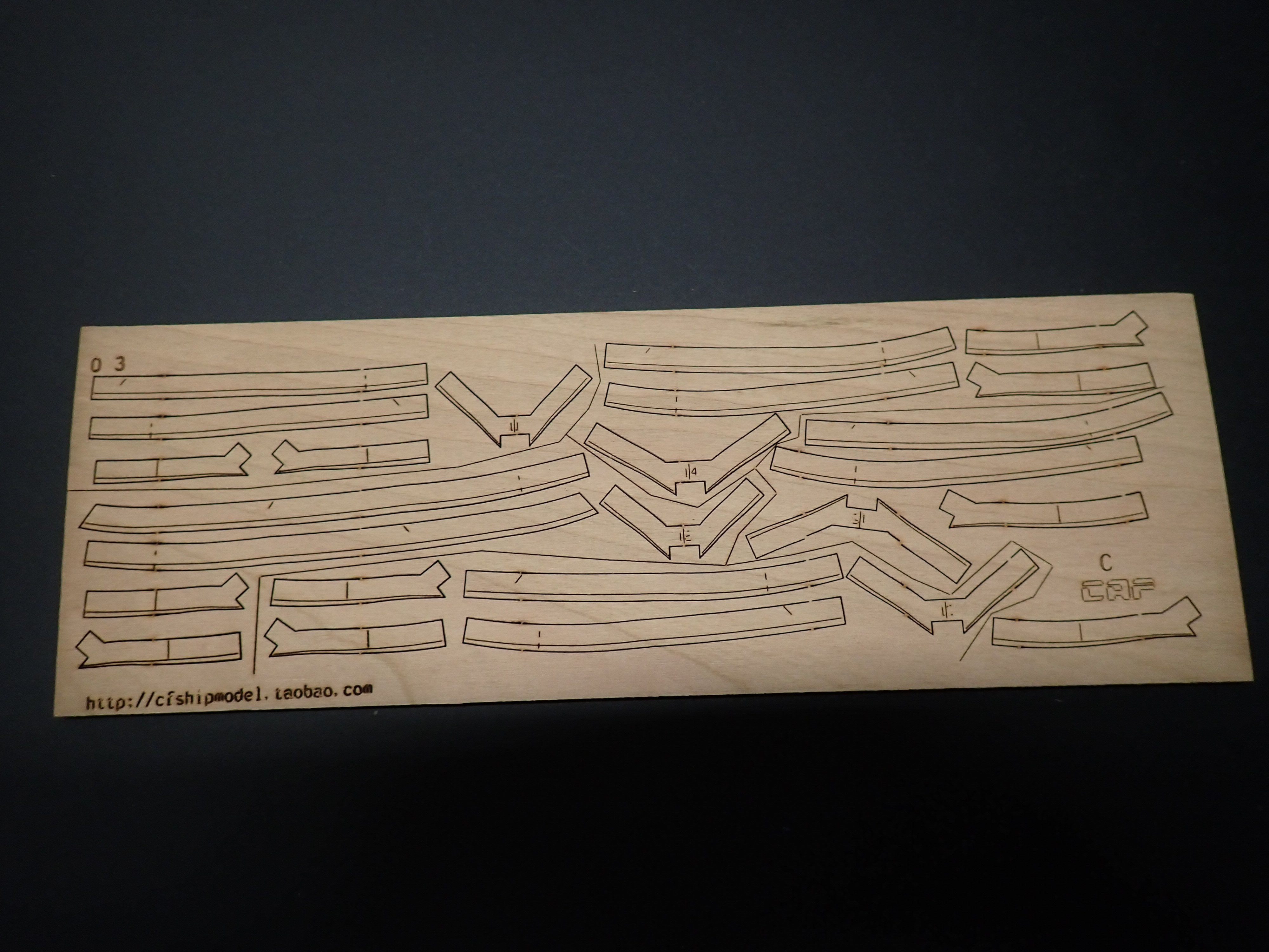
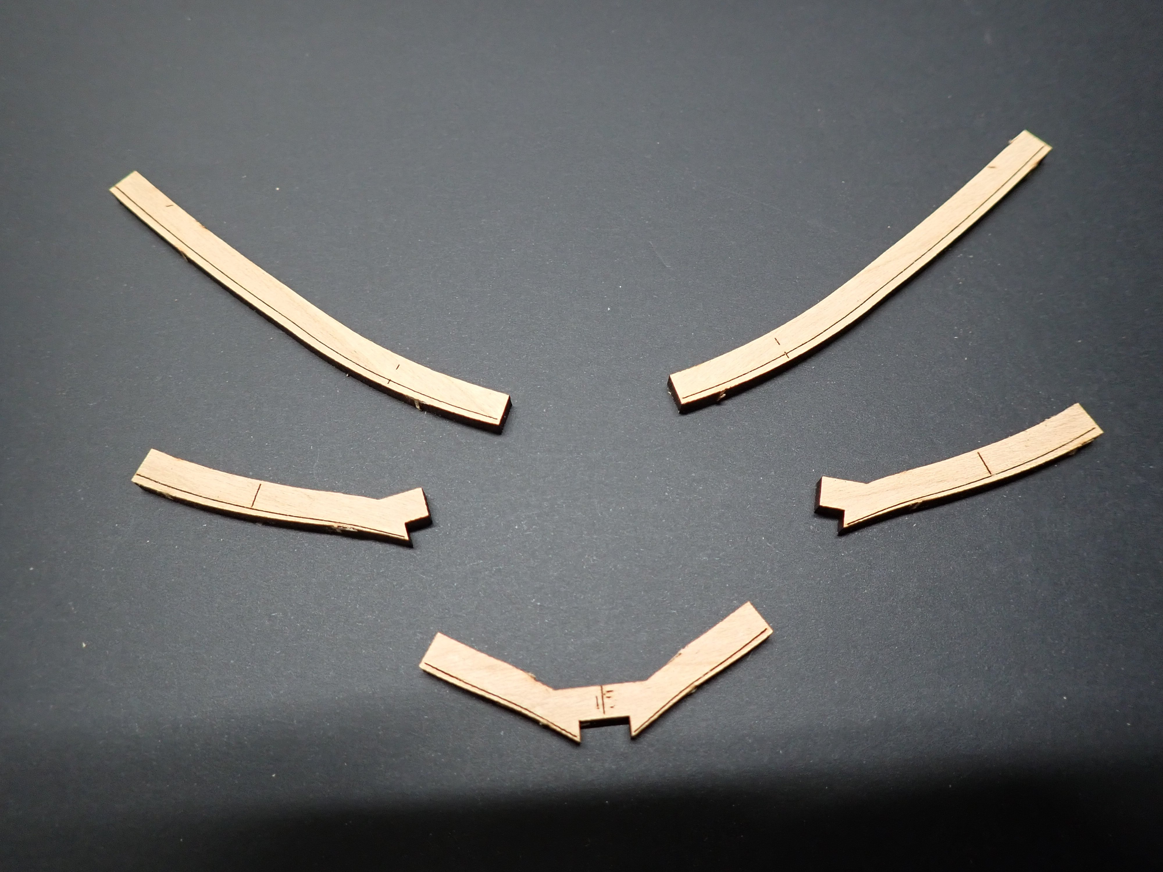
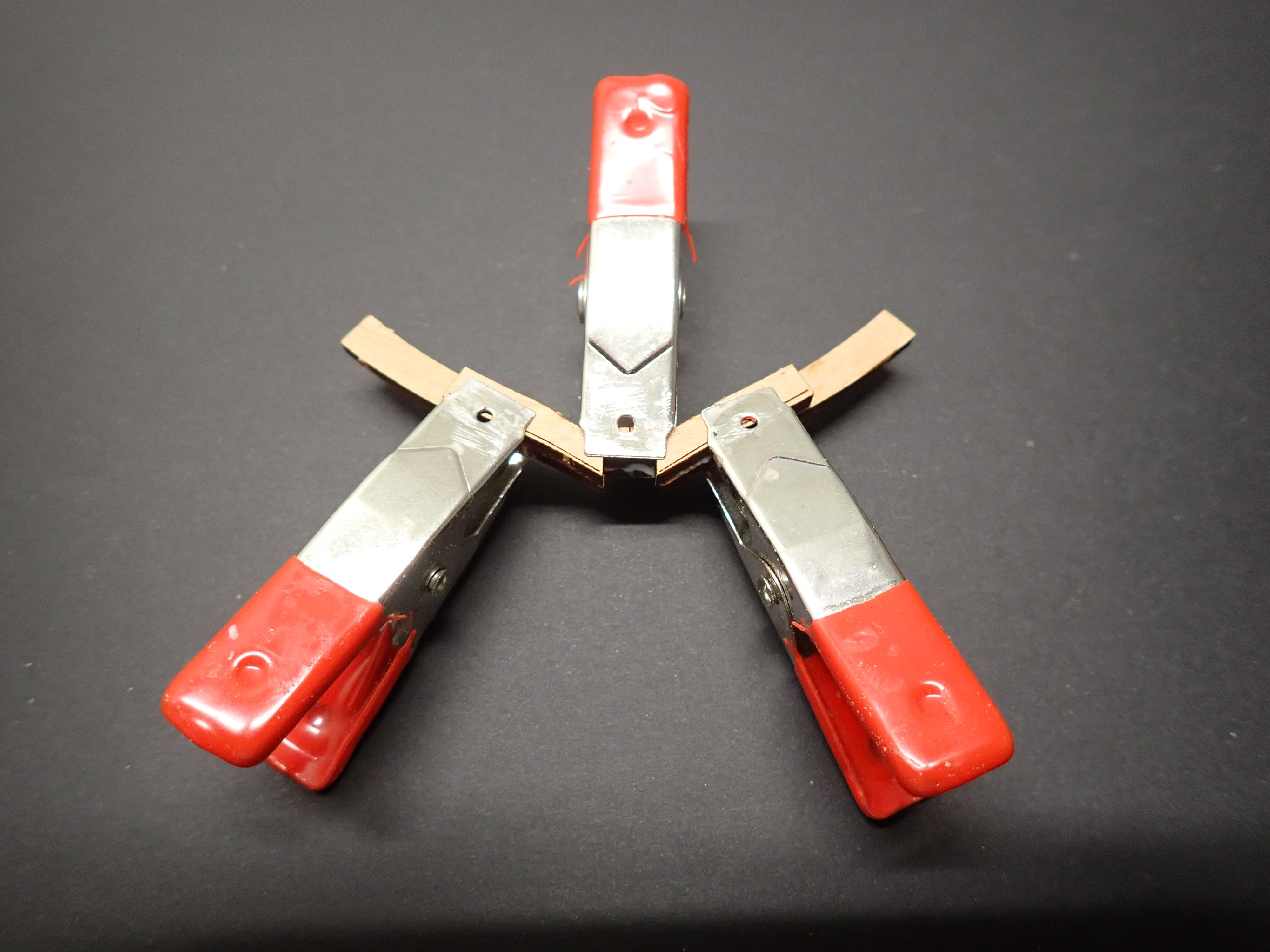
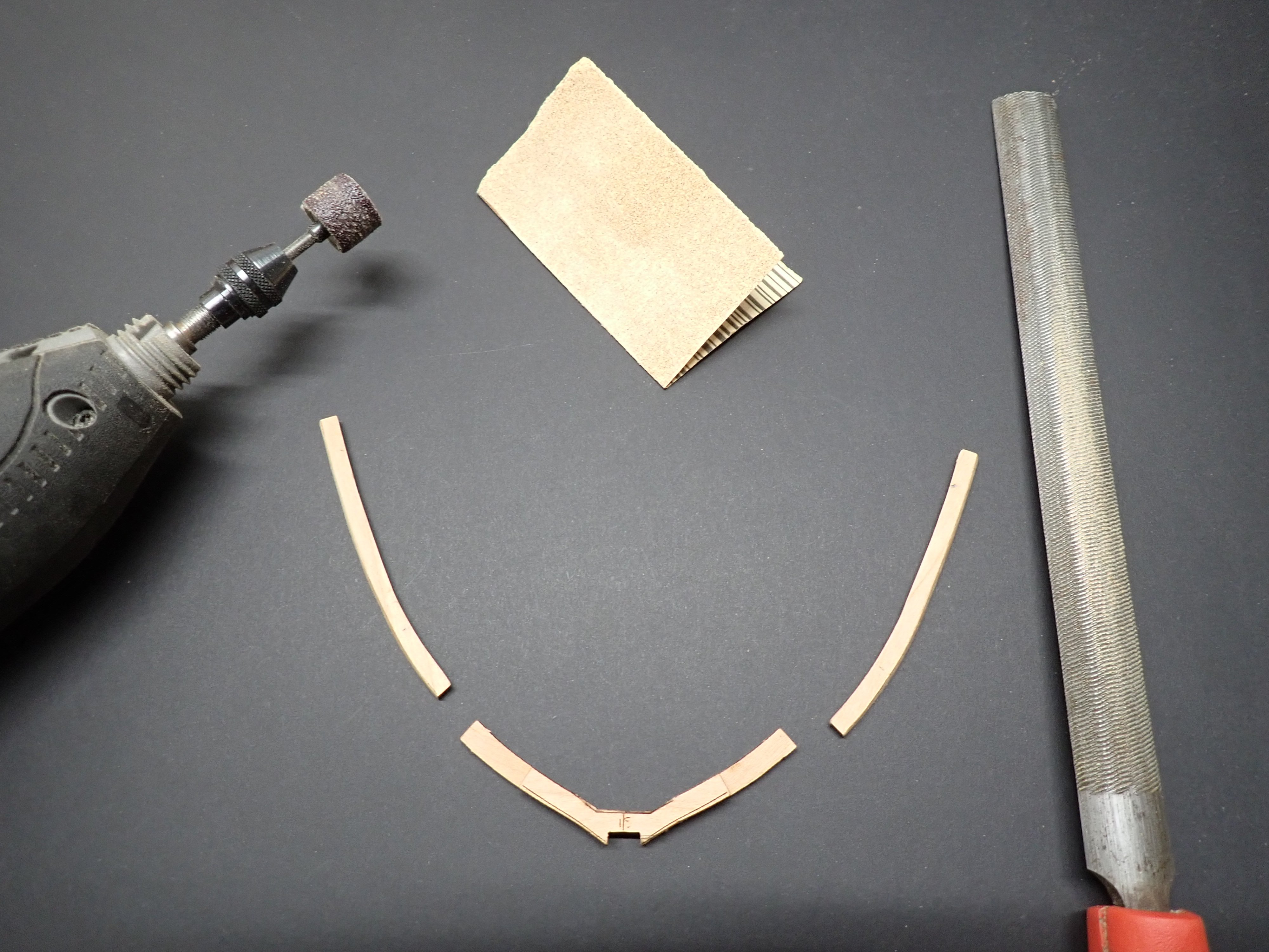
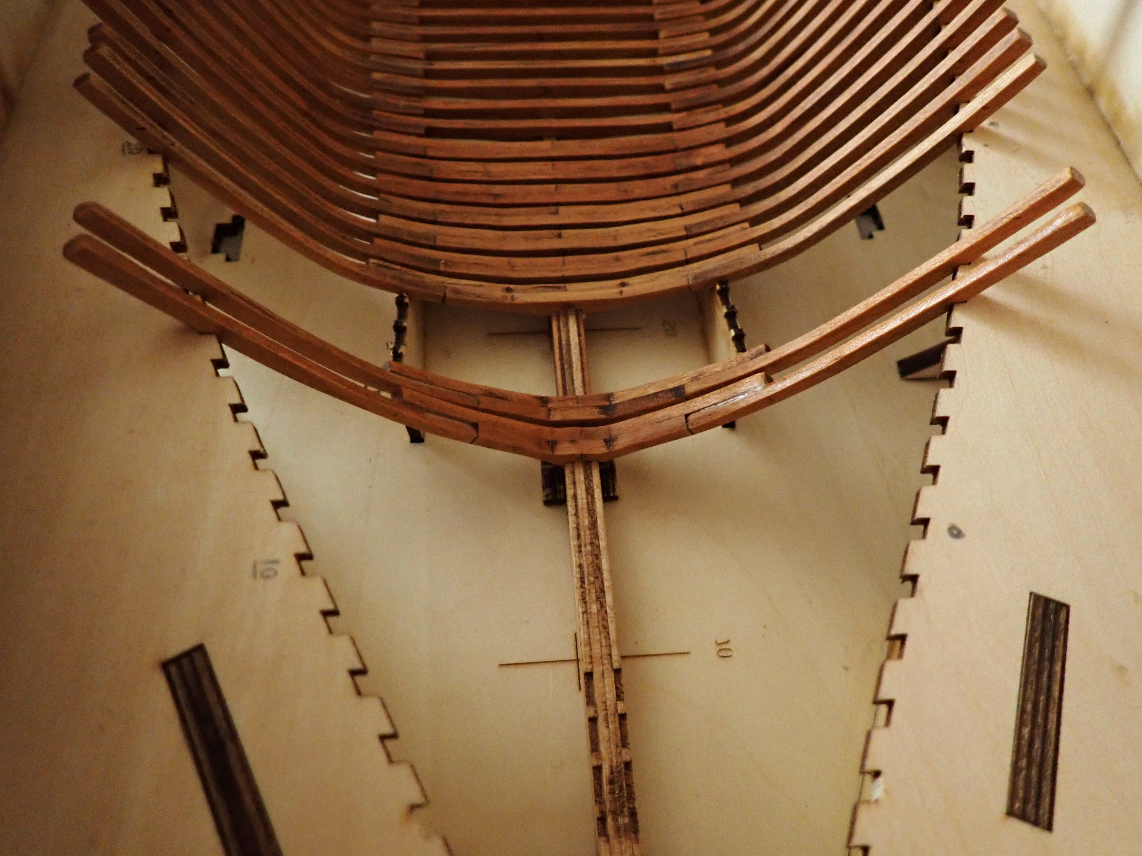
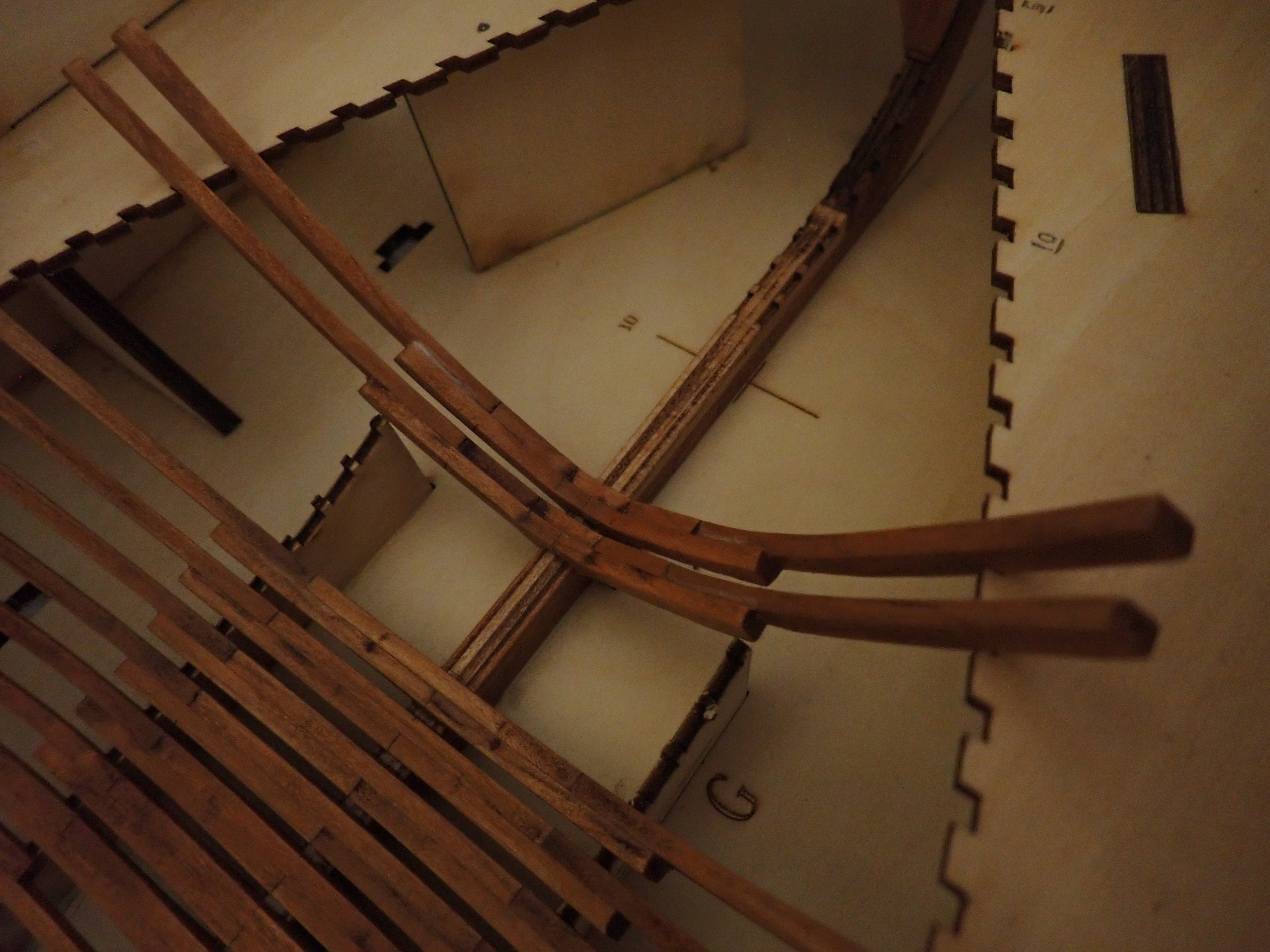
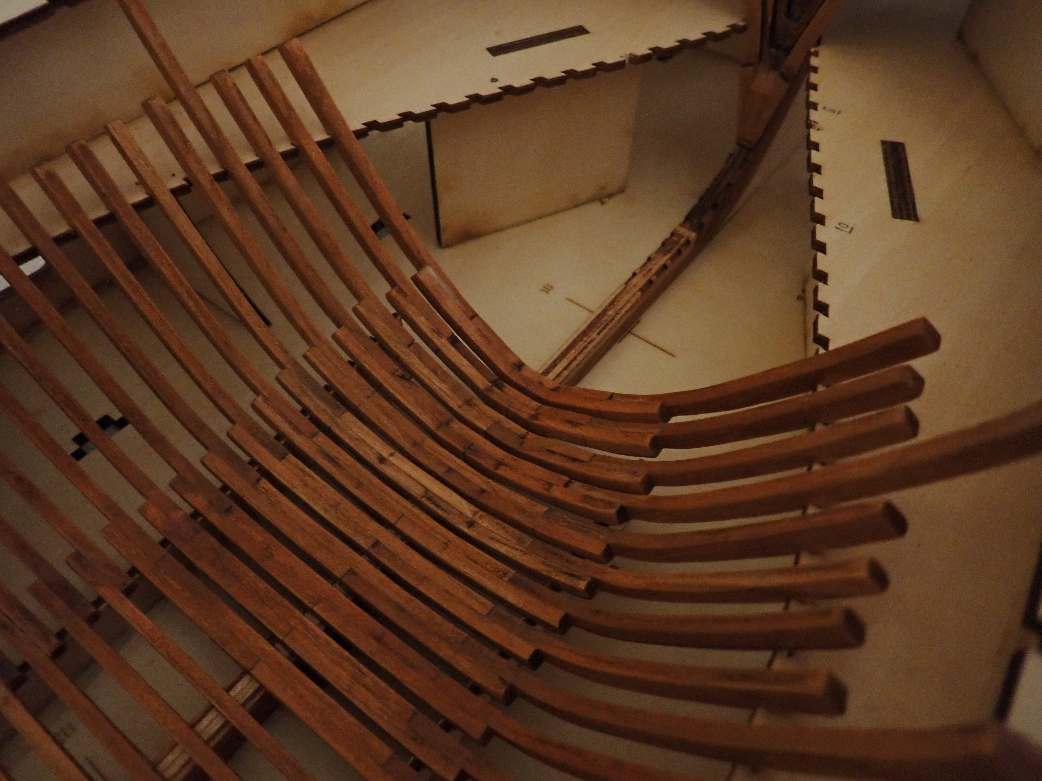
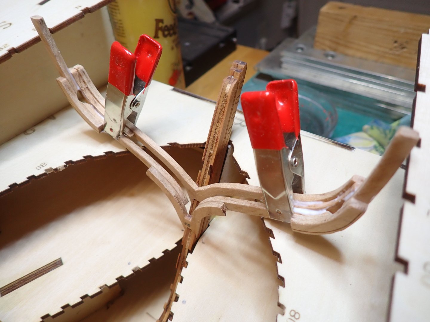
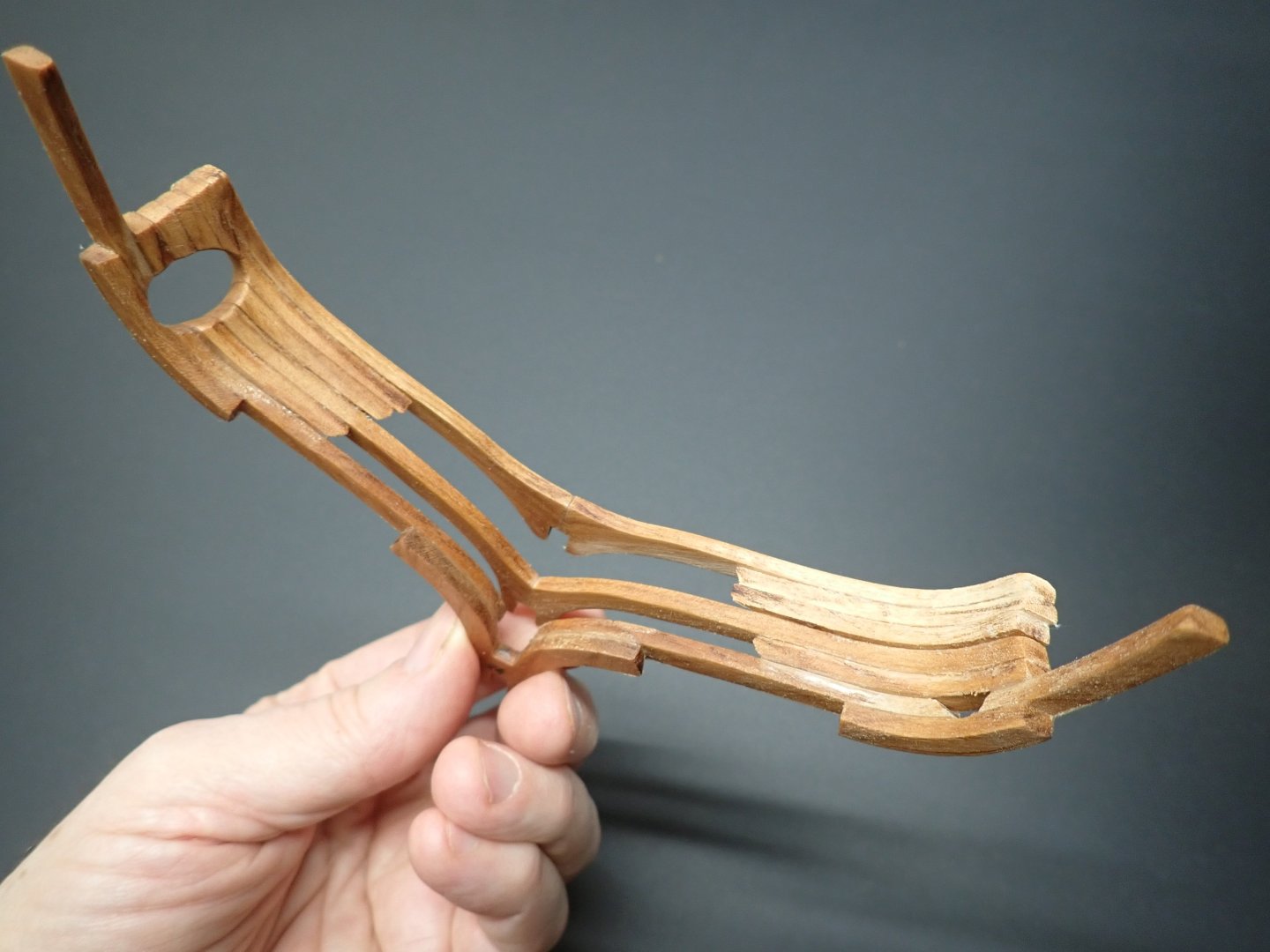
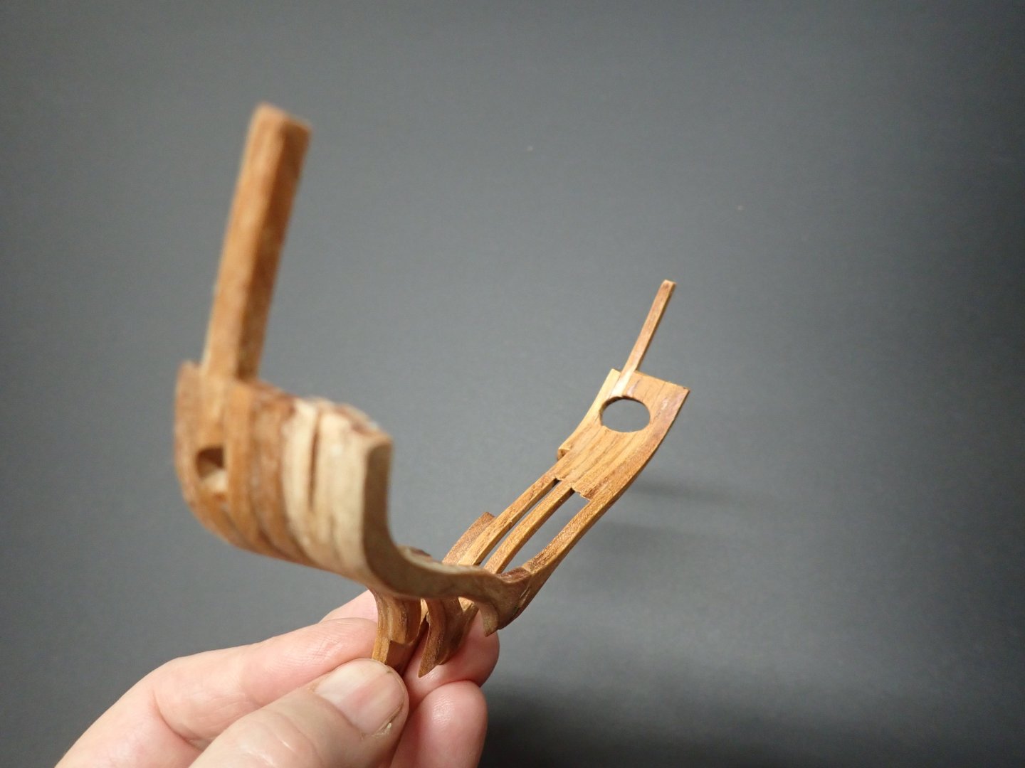
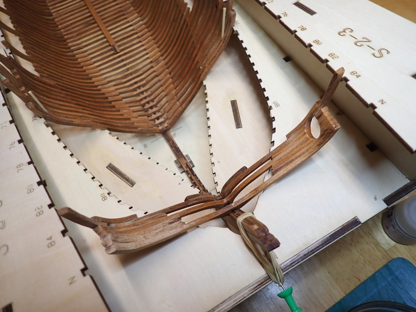
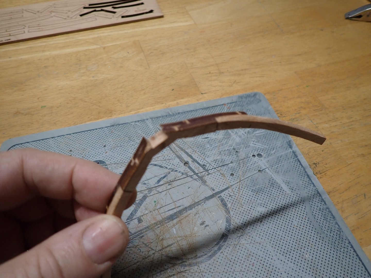
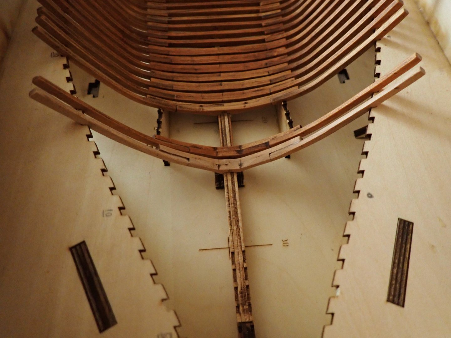
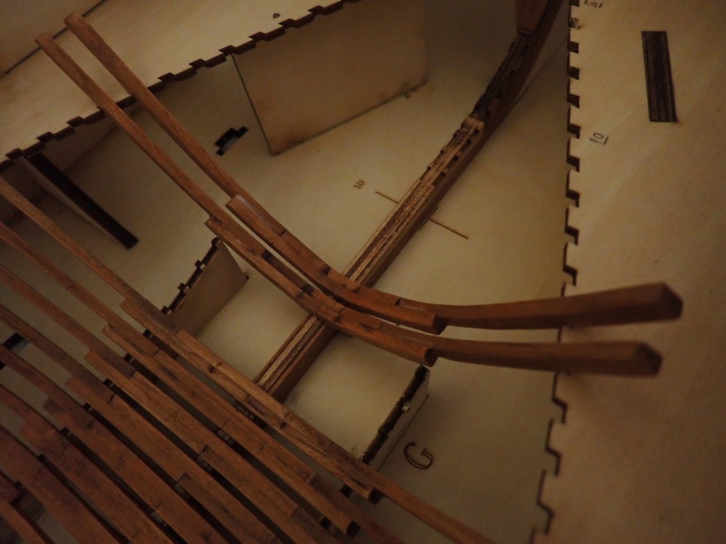
After studying the instructions (there are none) and the plans mainly, I decided to steer my attention to the stern. Instead of building Frames #71 to #80, I concentrated on the very last frames indicated by the plan and the Monograph. The reason is the lack of space, if you decide to glue the frames located before #80. The reasoning and the same approach were also used for the bow. There is a rather complex assembly taking place between Frame #84 and Frame #M. The three frames must be part of the same set and must fit perfectly on the stern keel. As usual, the first step is to fit the frame footing on the keel, after using my Dremel to start fairing the frame. Verification that it fits well on the keel. Then the sides are glued in position, in the cradle. The same is done for the following Frame "J". Finally, the intermediate parts are glued (after some fairing) and the two frames are positioned and glued together: It is all extremely delicate and I am not even sure this assembly will look okay with the rest of the hull and frames. The third frames "M" is glued as well without forgetting the intermediate parts and set in position as described above. We end up with something that looks like the picture below: It is all extremely delicate and the two openings for the guns must be carefully carved on each side. The part is now finished and I will post more pictures soon. Yves


- 185 replies
-
- 13
-
-
-
You pulled that one very well. These kits are not easy to put together and your finished model is stunning. Yves
-
Yes, the infamous Supersized match..... Yves
-
Make sure that the "bucket" is absolutely waterproof. Resin manages to find the smallest hole or crack by capillarity. It is worse than water. Yves
-
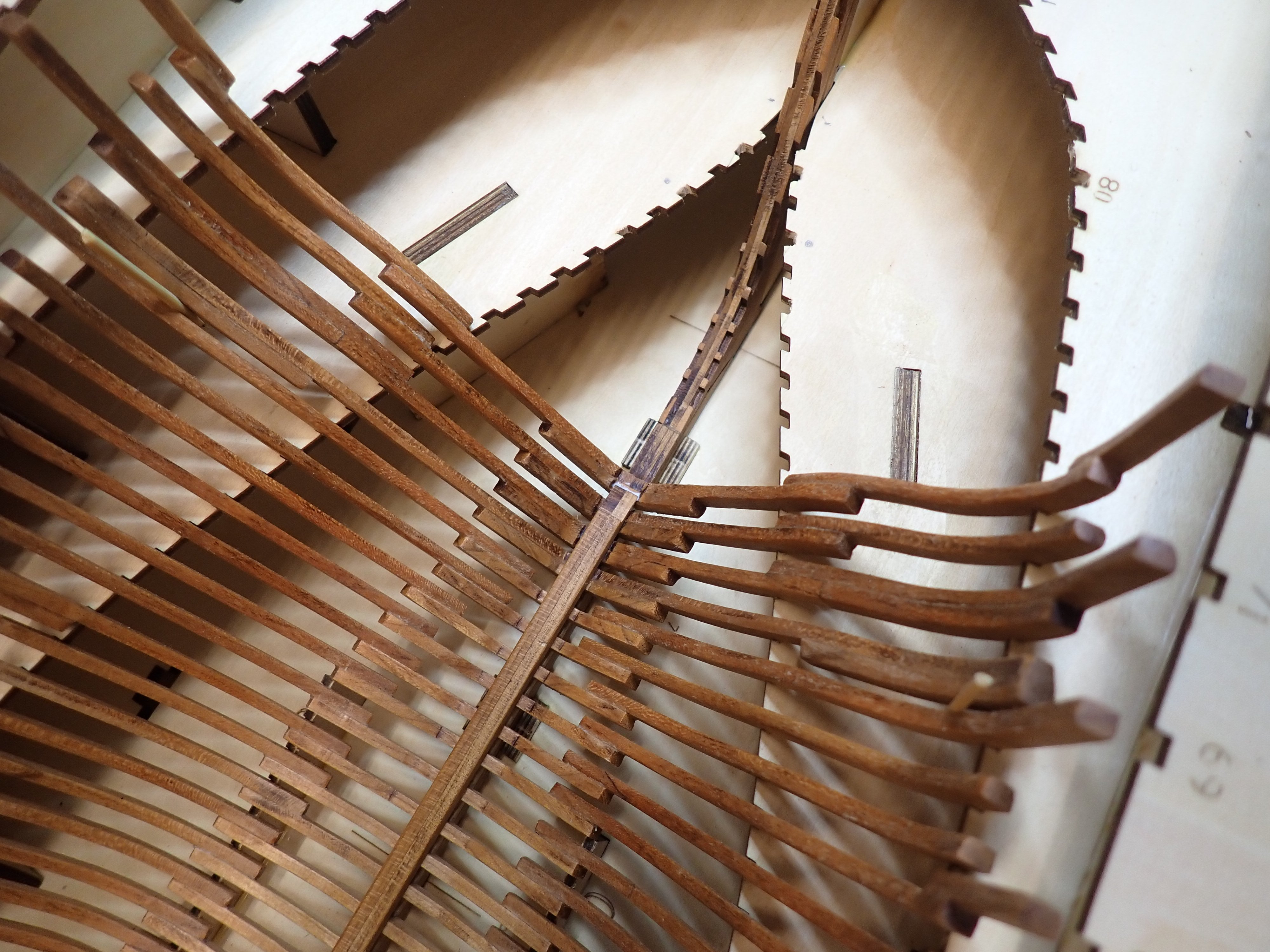
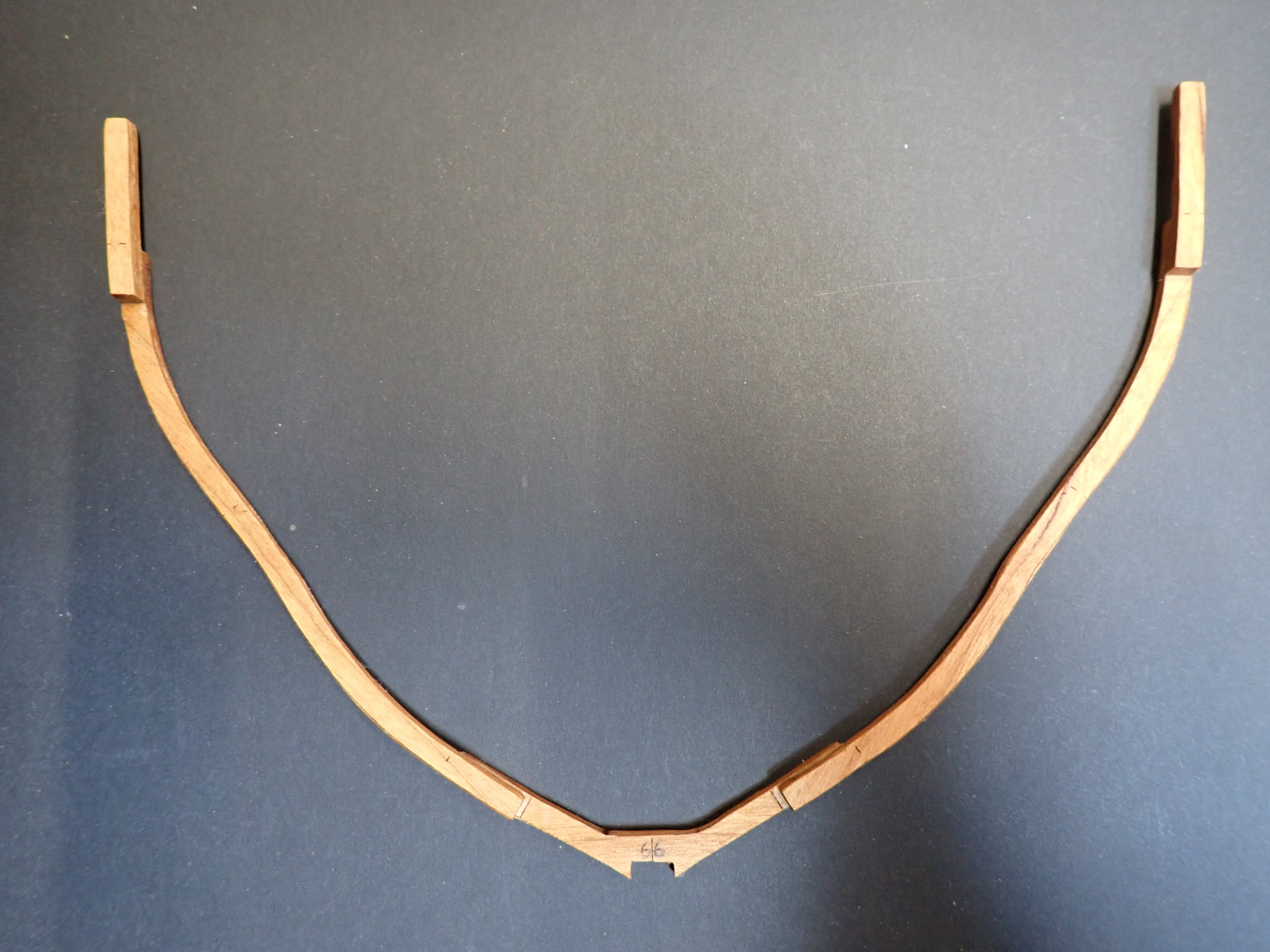
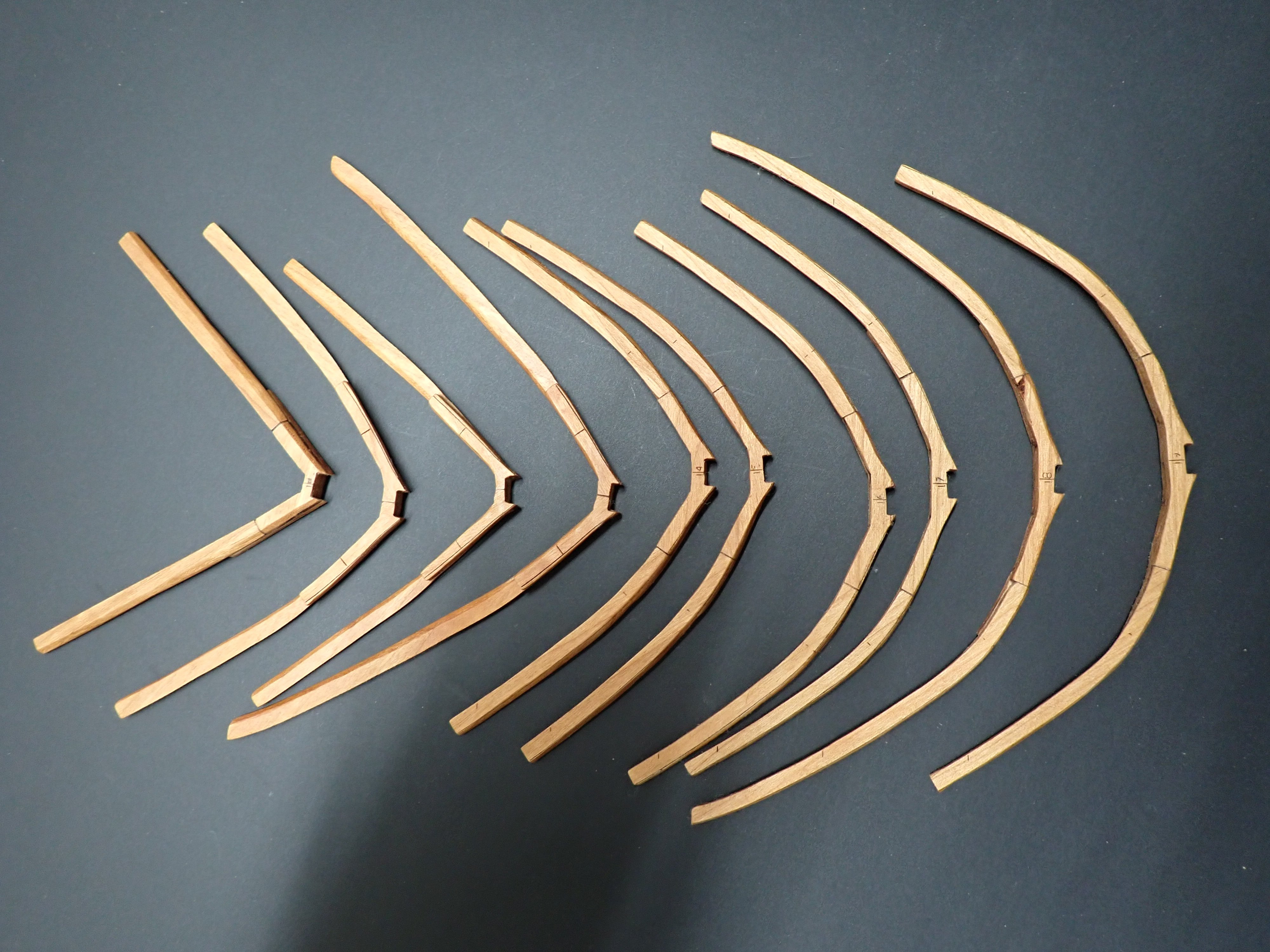
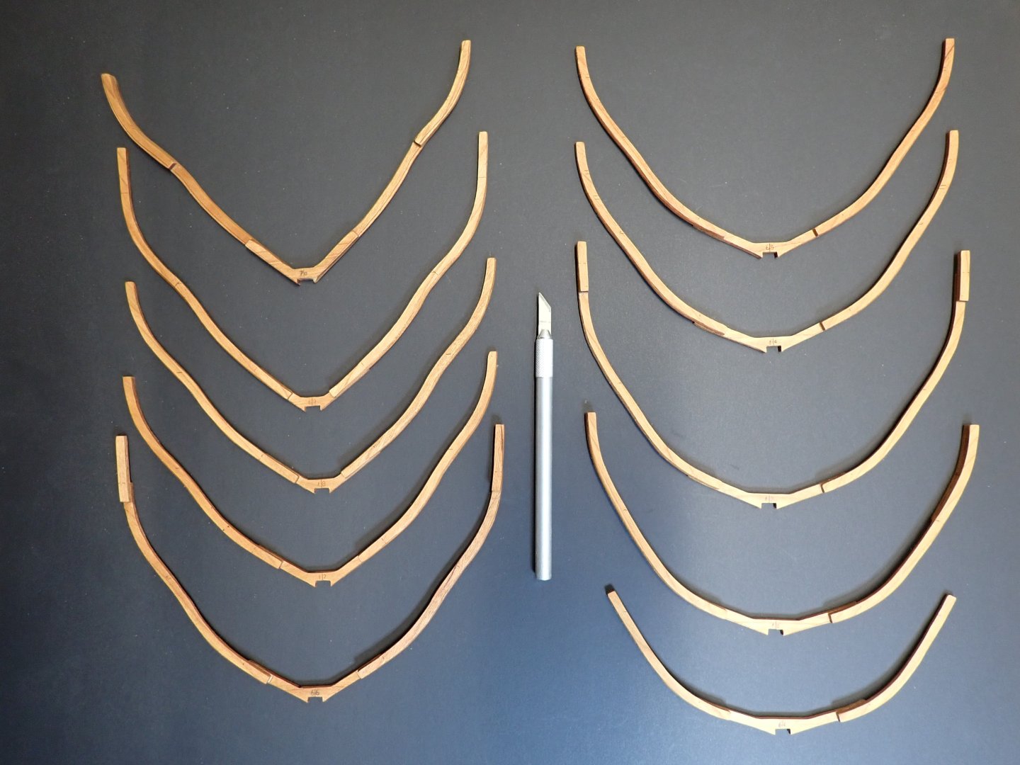
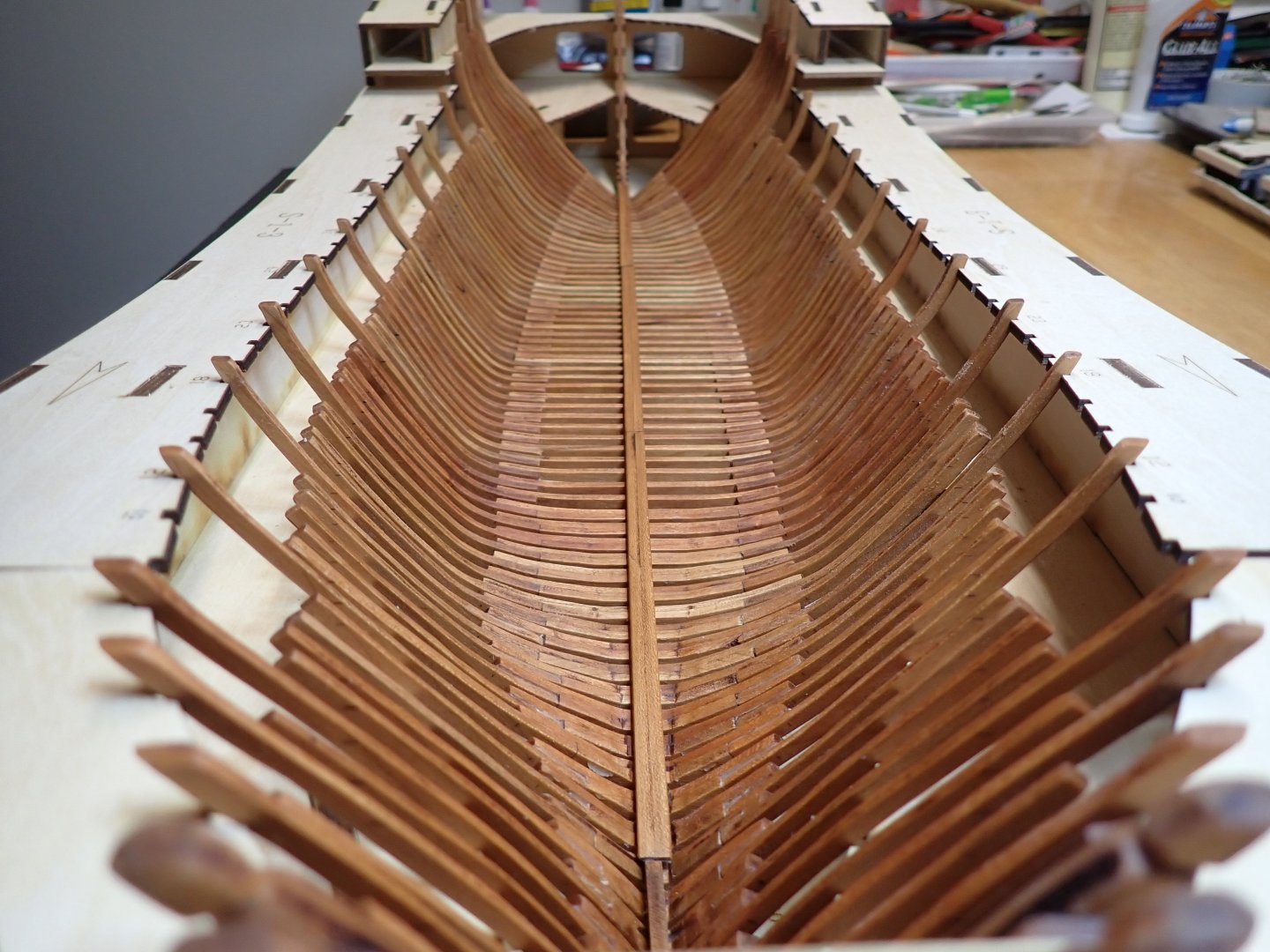
Frames #61 to #70 have been completed. These are a lot more difficult and do require to be taken as a little project, one at a time. Consulting the plan and the Monograph helps tremendously, as well as creating a routine and sticking to it. All frames are made of cherry wood and finely sanded, oiled and waxed. The most delicate was #66, composed of 5 parts and rather difficult to fit it into the cradle: All the new frames are being dry fitted. No glue yet. Just 18 more to go..... Last segment of the keelson is not glued yet. Yves

- 185 replies
-
- 17
-
-
Kevin, There are no silly questions. Thank you for following up this log. Yves
-
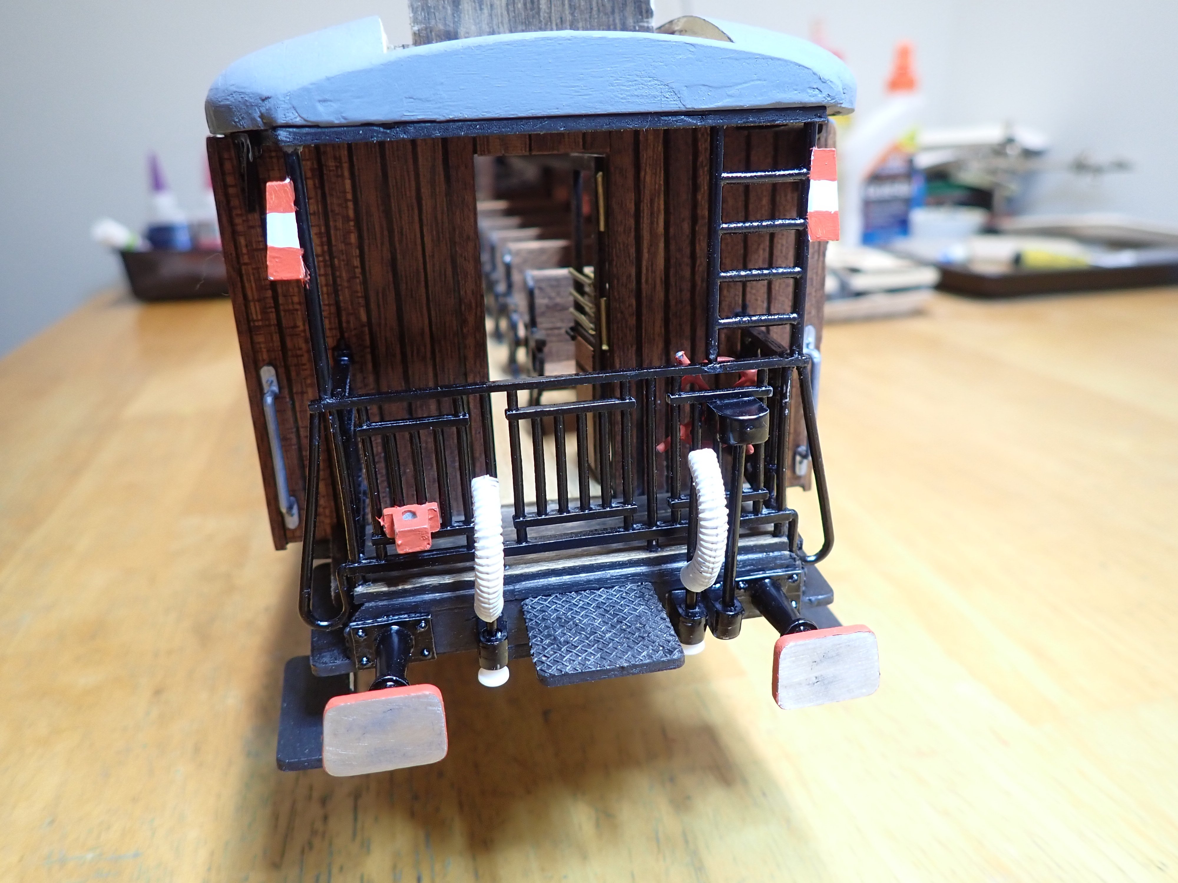
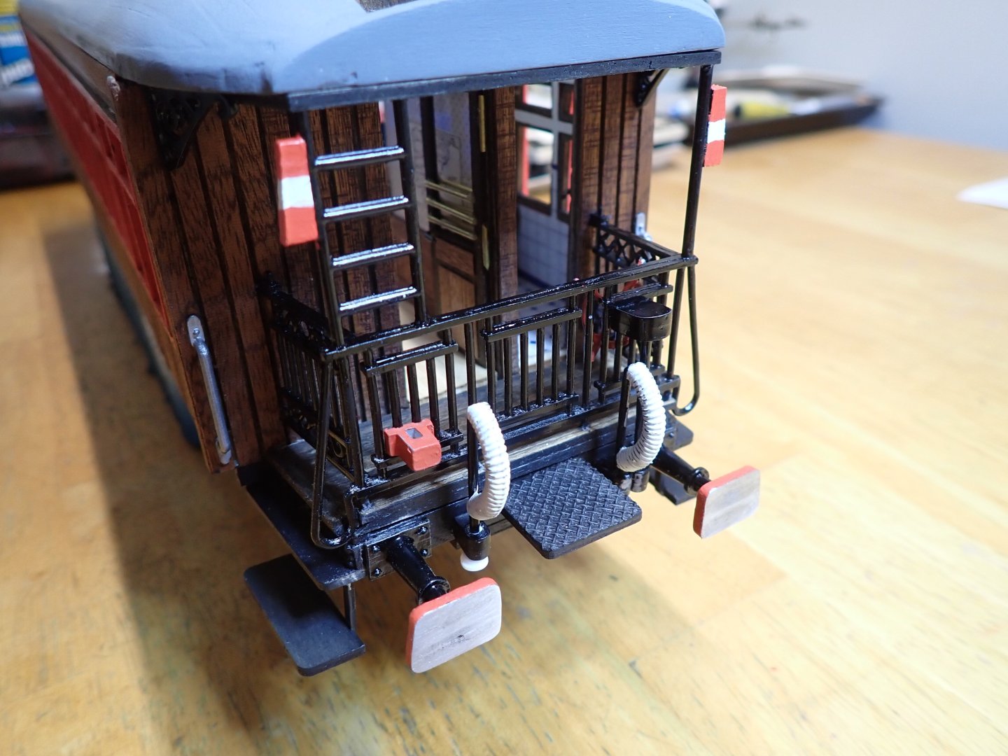
A few updates on this passenger car: I have just completed the ends. I gave up on the couplers provided by OCCRE, as they are not reliable, are not prototypical and makes no sense. Instead that Spanish car will be equipped with American knuckle couplers from Kadee. This way, I will be able to pull this car with an American engine and it will look better overall. I still have to paint the trucks, which is not an easy task as the wheels have to be protected from the spray. We are coming to an end for this kit. Yves

- 91 replies
-
- 13
-
-
-
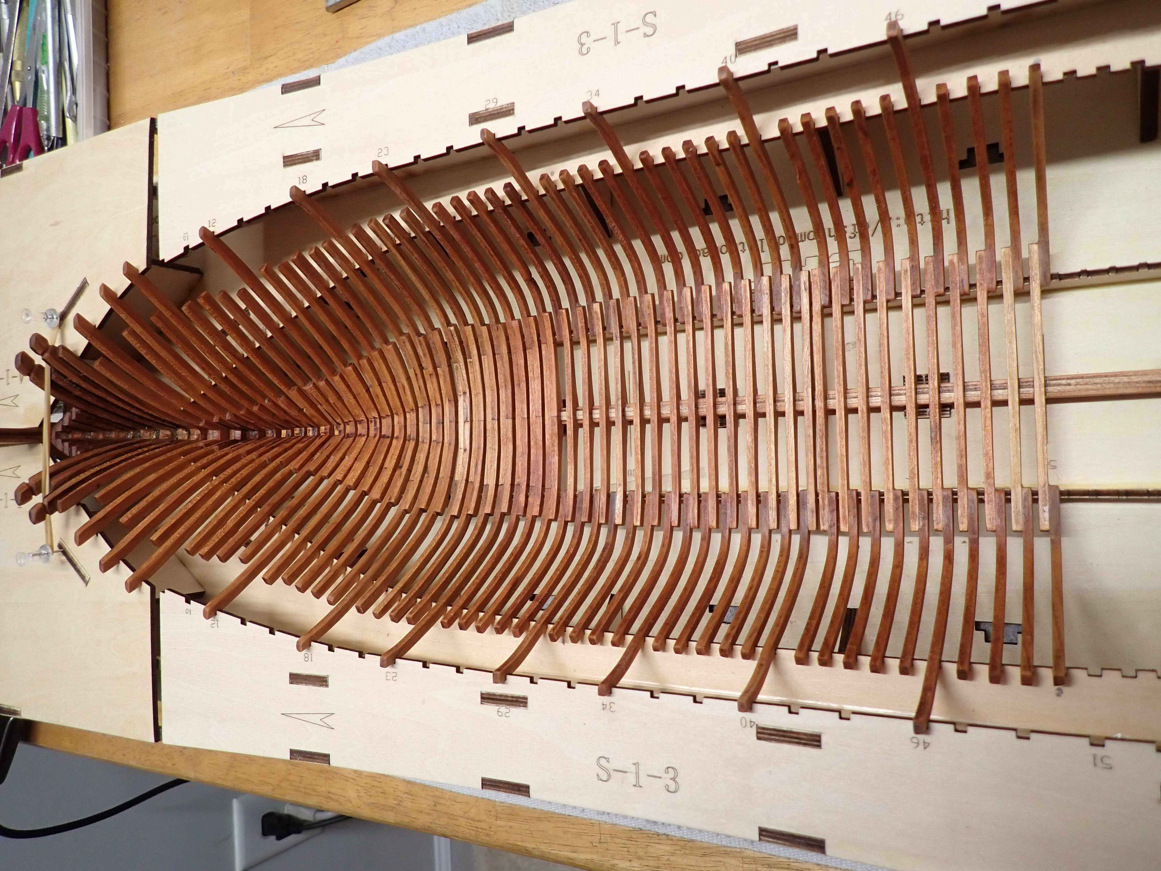
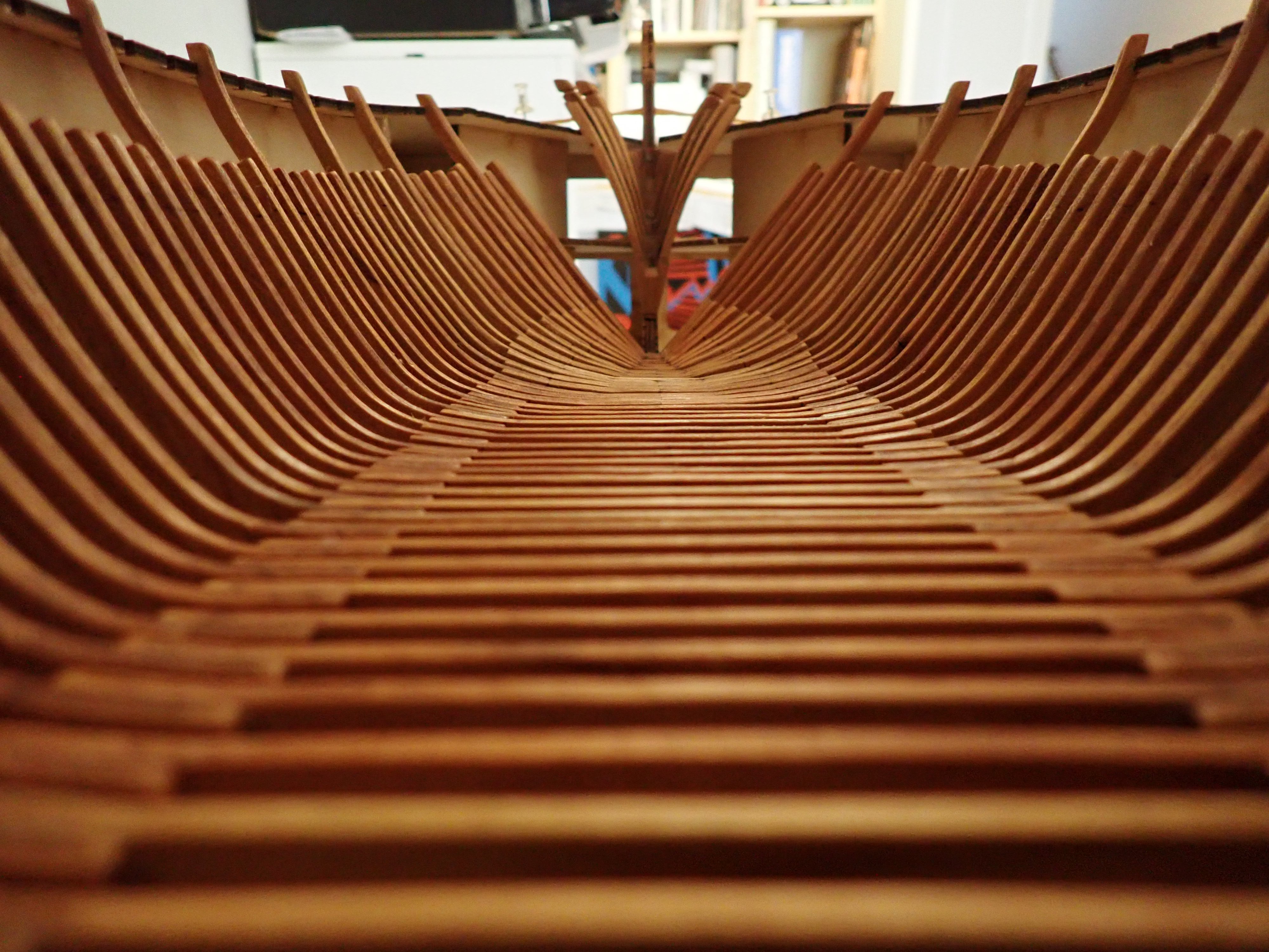
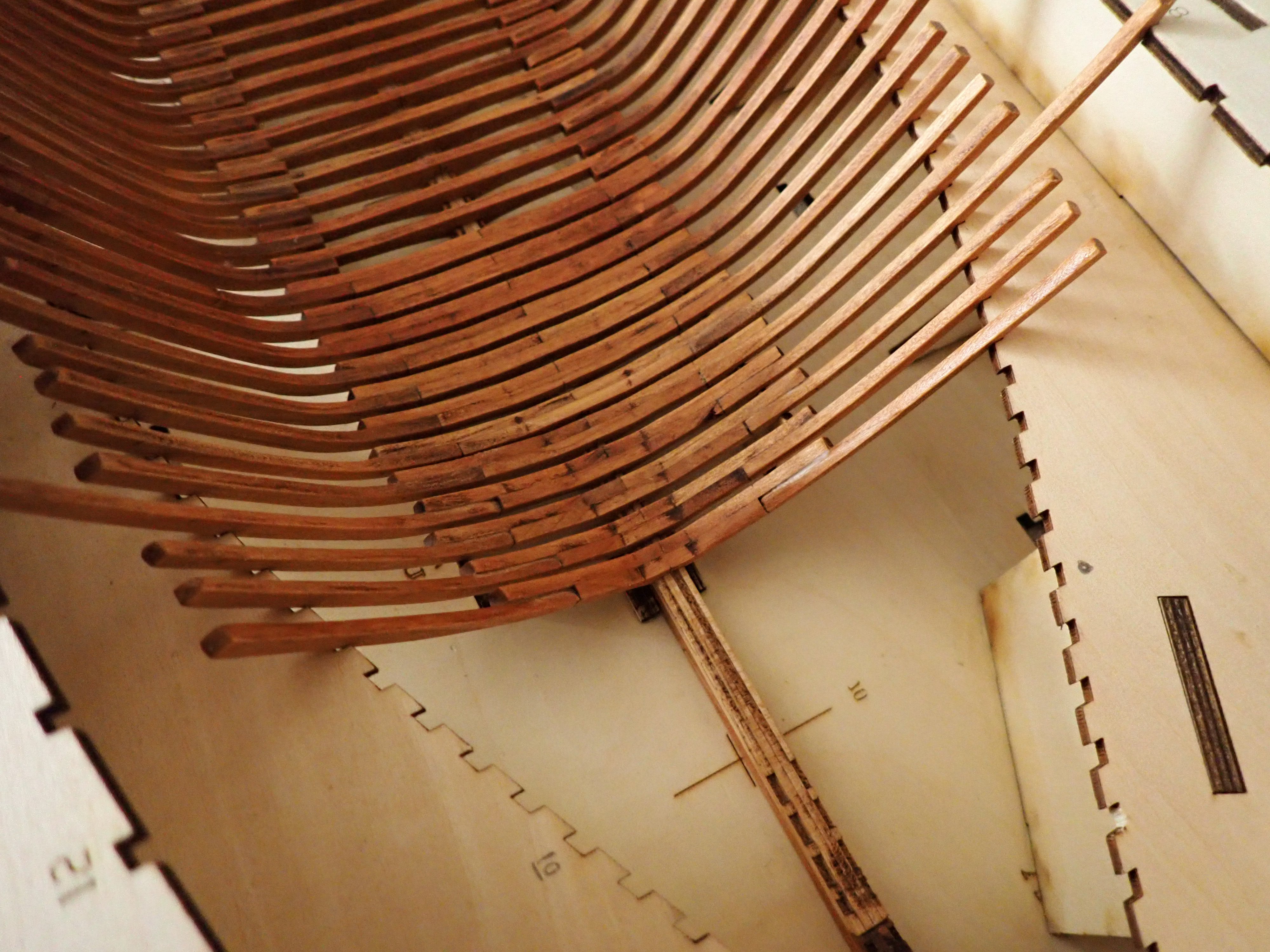
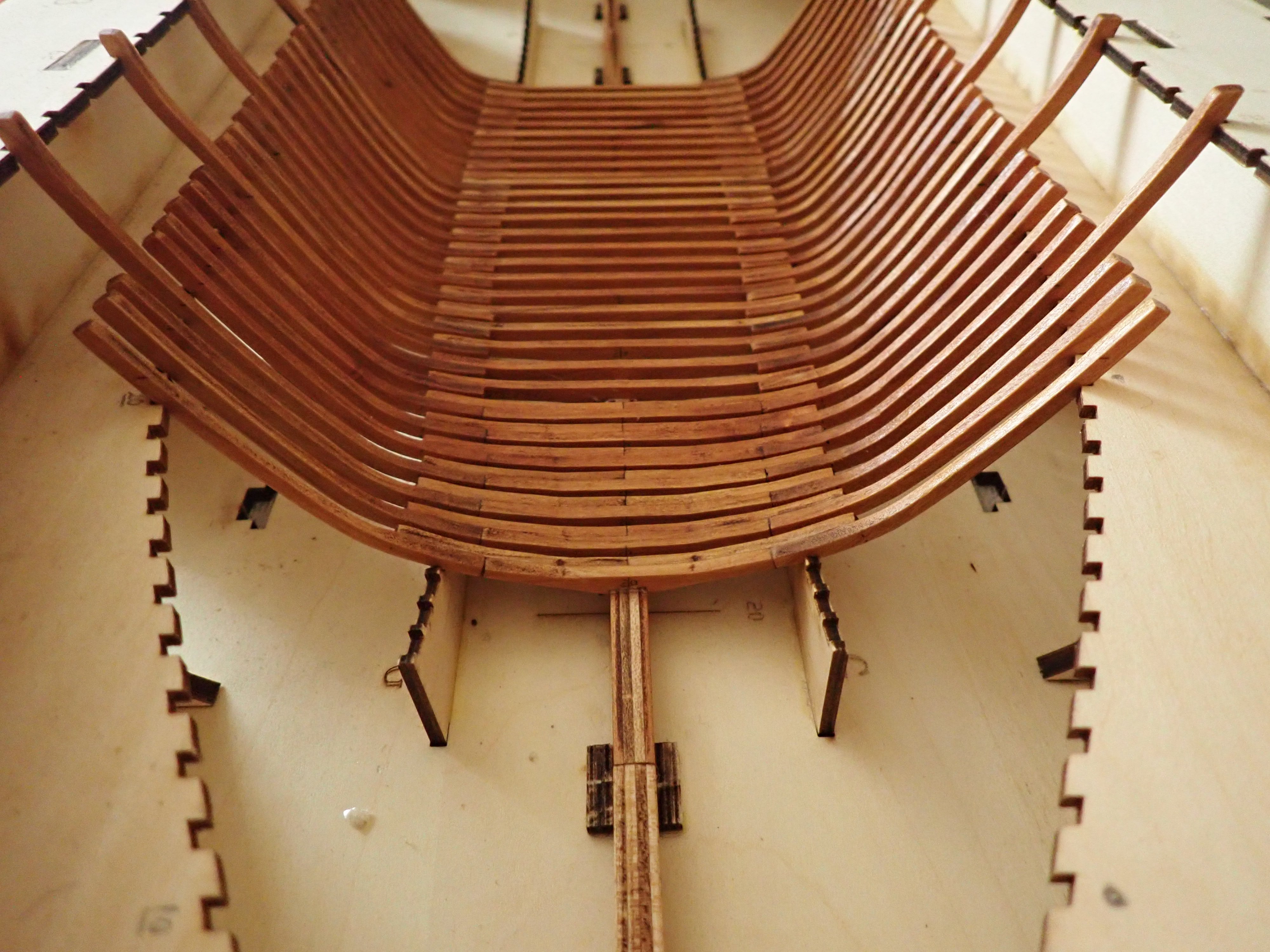
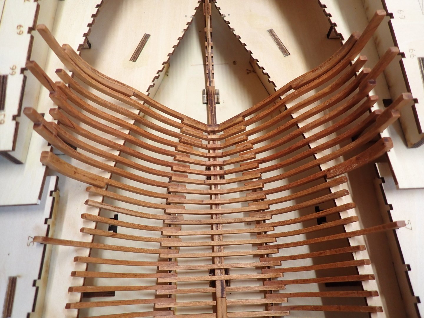
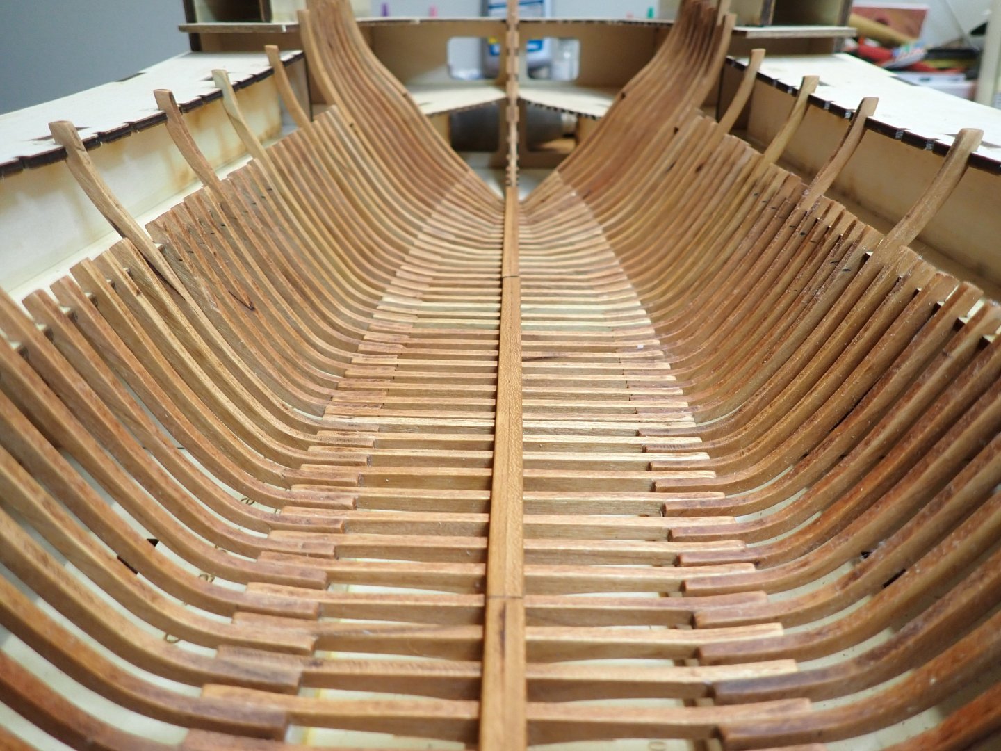
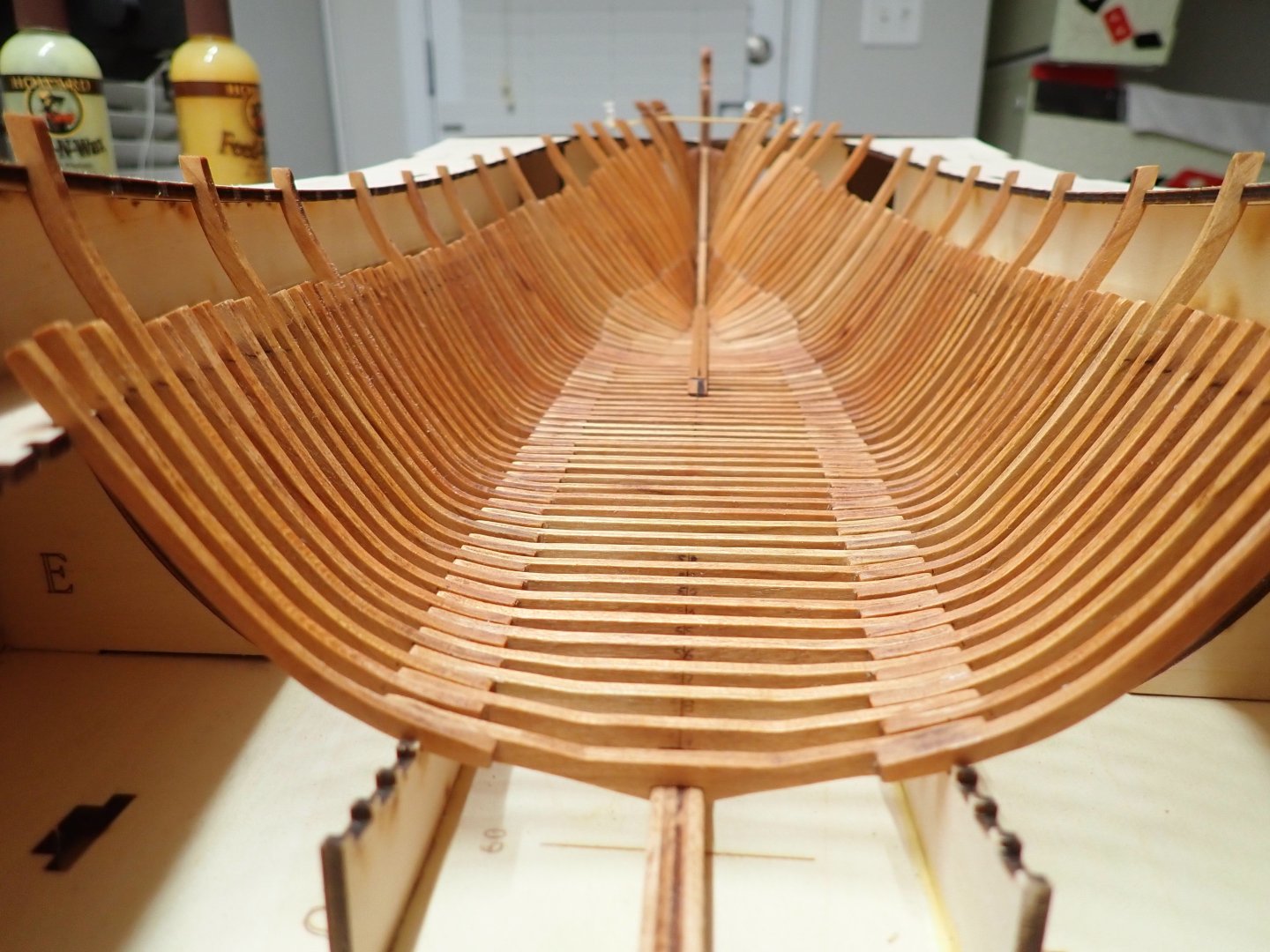
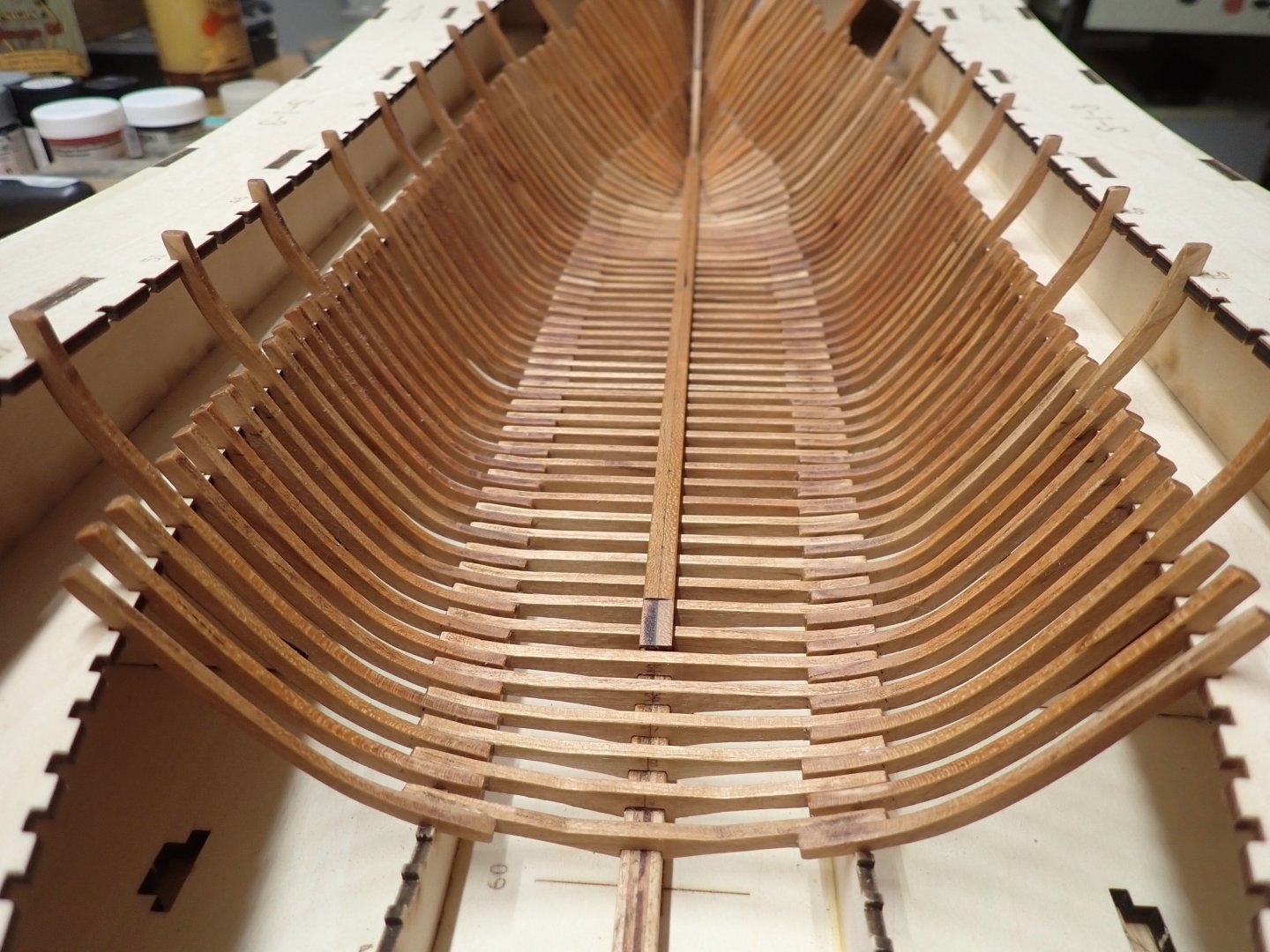
A little update, still working on the frames. It seems endless.... Frames #51 to #60 have been built. These frames are still part of what can be considered "easy frames" as they do not require very much of a fairing (inside and outside) and are composed of only three parts. At this point, Frames #1 to #60 have been installed and glued on the keel: I also dry-fitted the keelson. Yves
- 185 replies
-
- 16
-
-
-
A real beauty, Ras. And what an unusual model on top of that. Yves
- 128 replies
-
- 3
-
-
- zulu
- sternwheeler
- (and 1 more)
-
Impressive work that this guy is doing.... He knows his stuff, for sure. Yves
-
Beautiful hull. It looks very promising. Yves
-
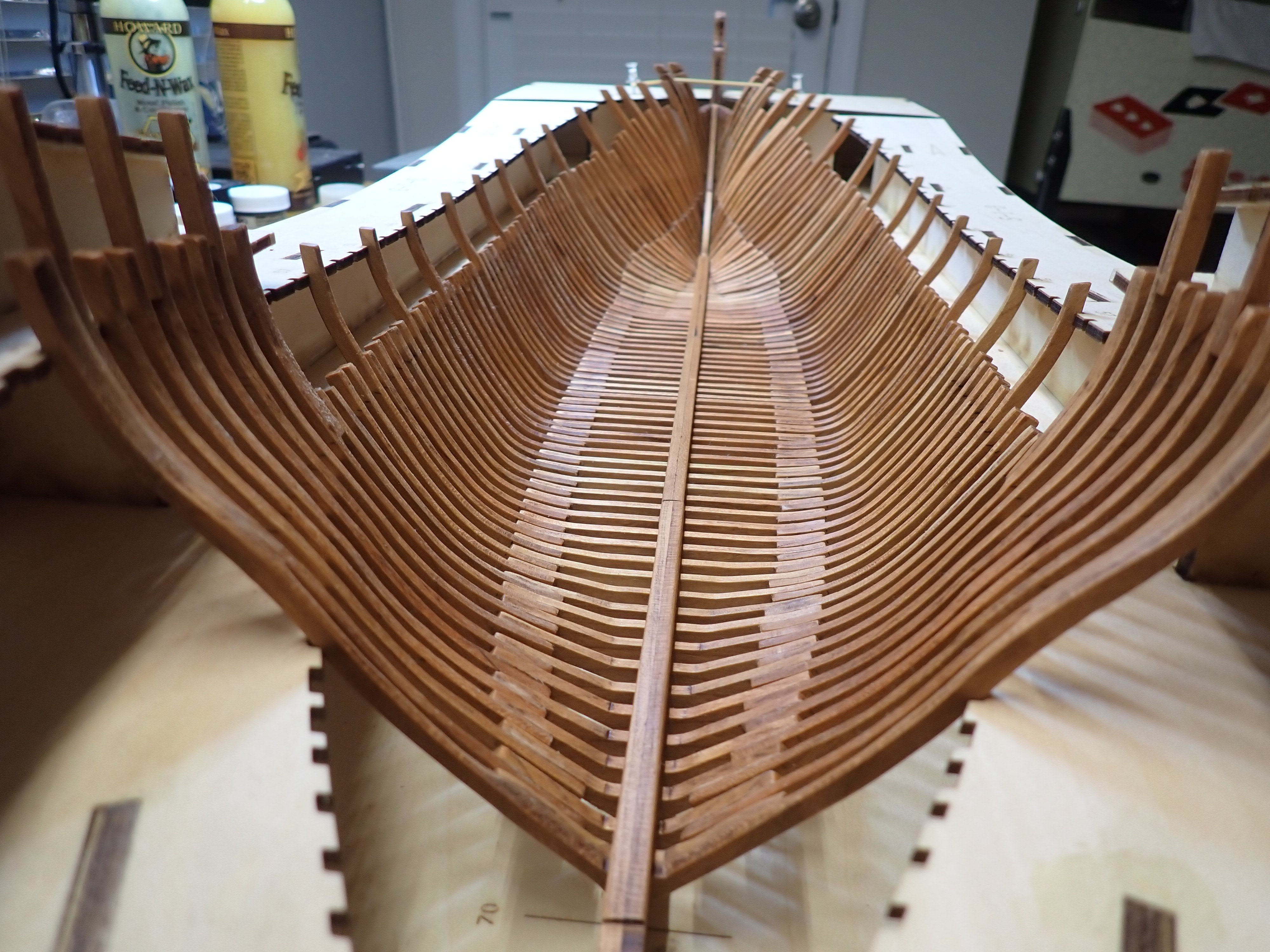
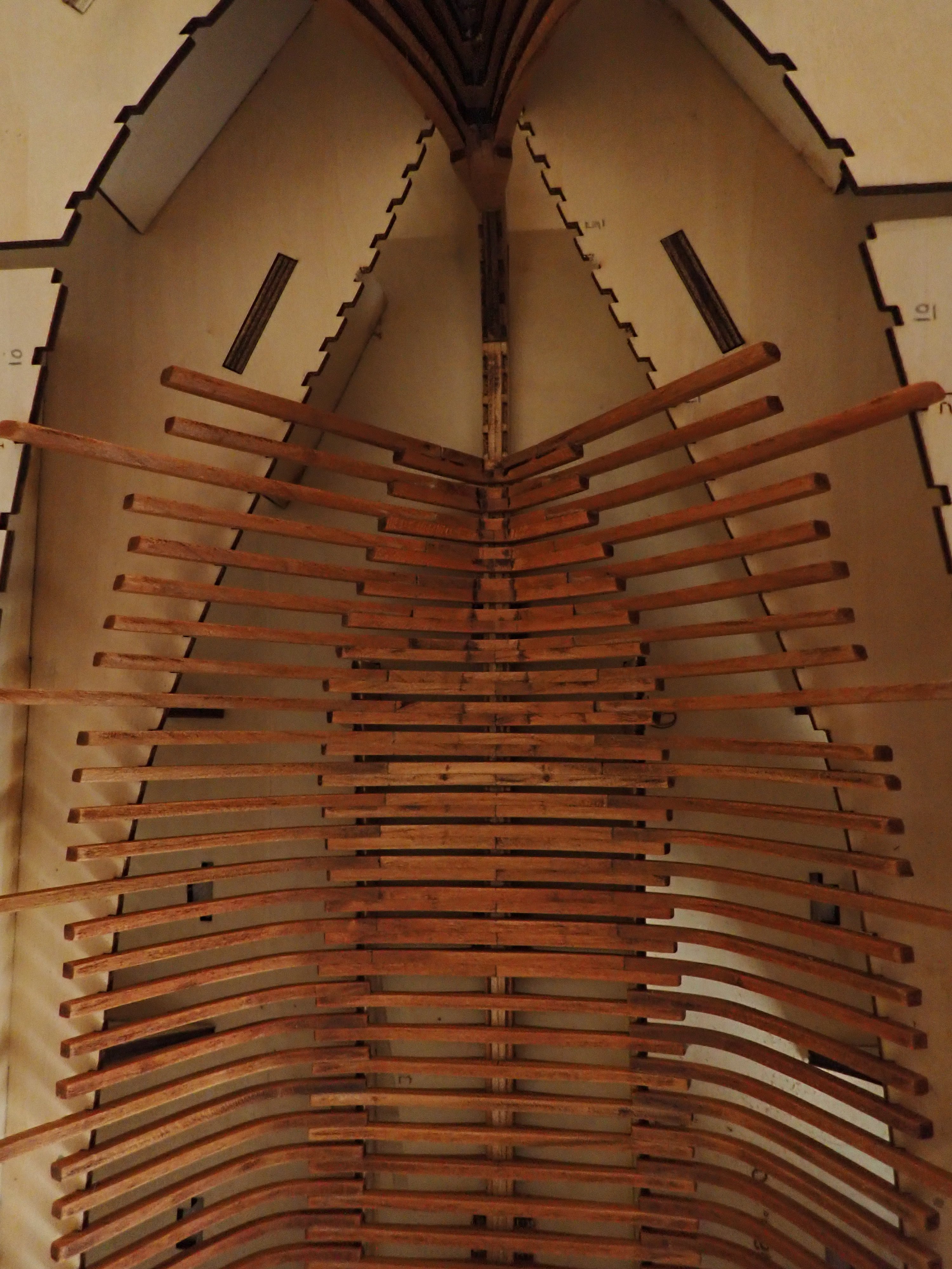
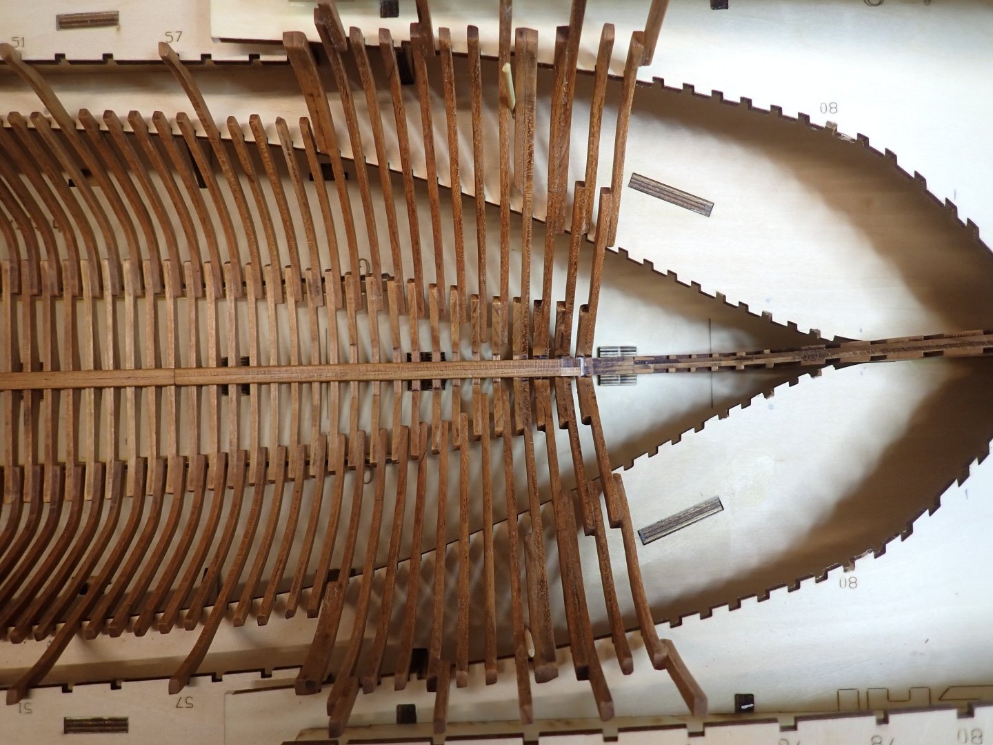
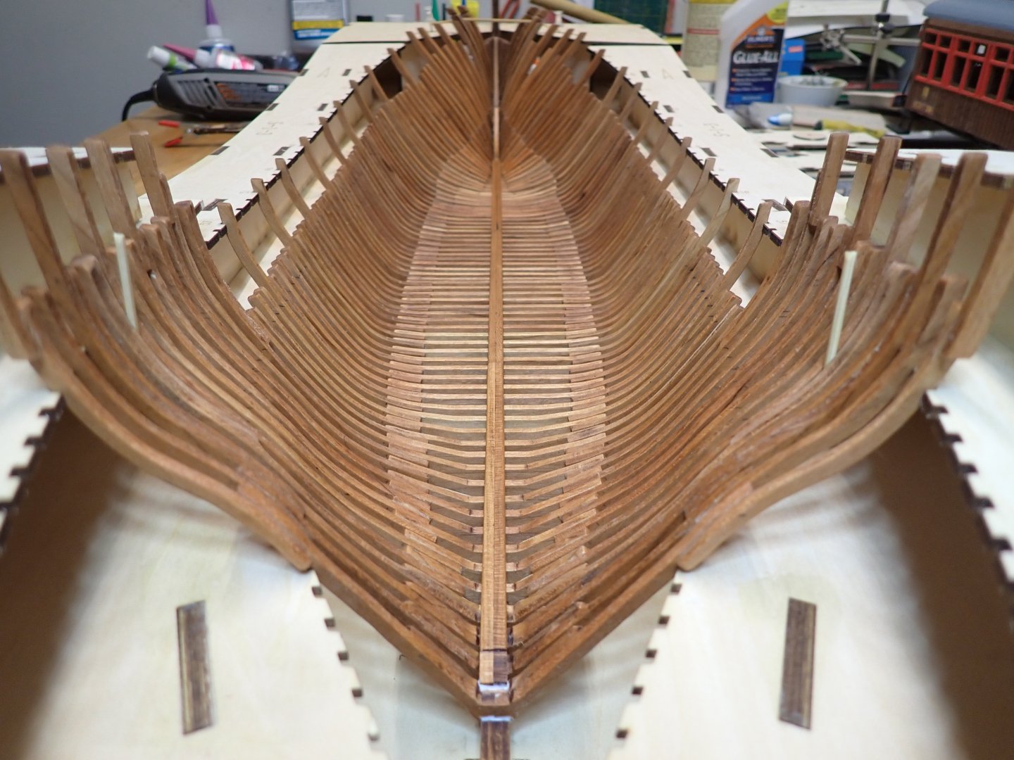
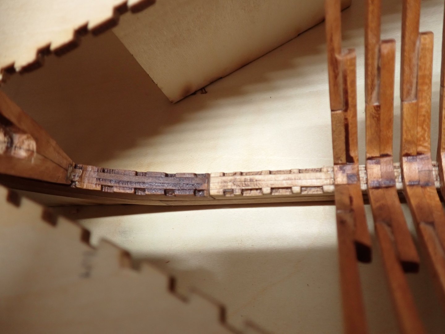
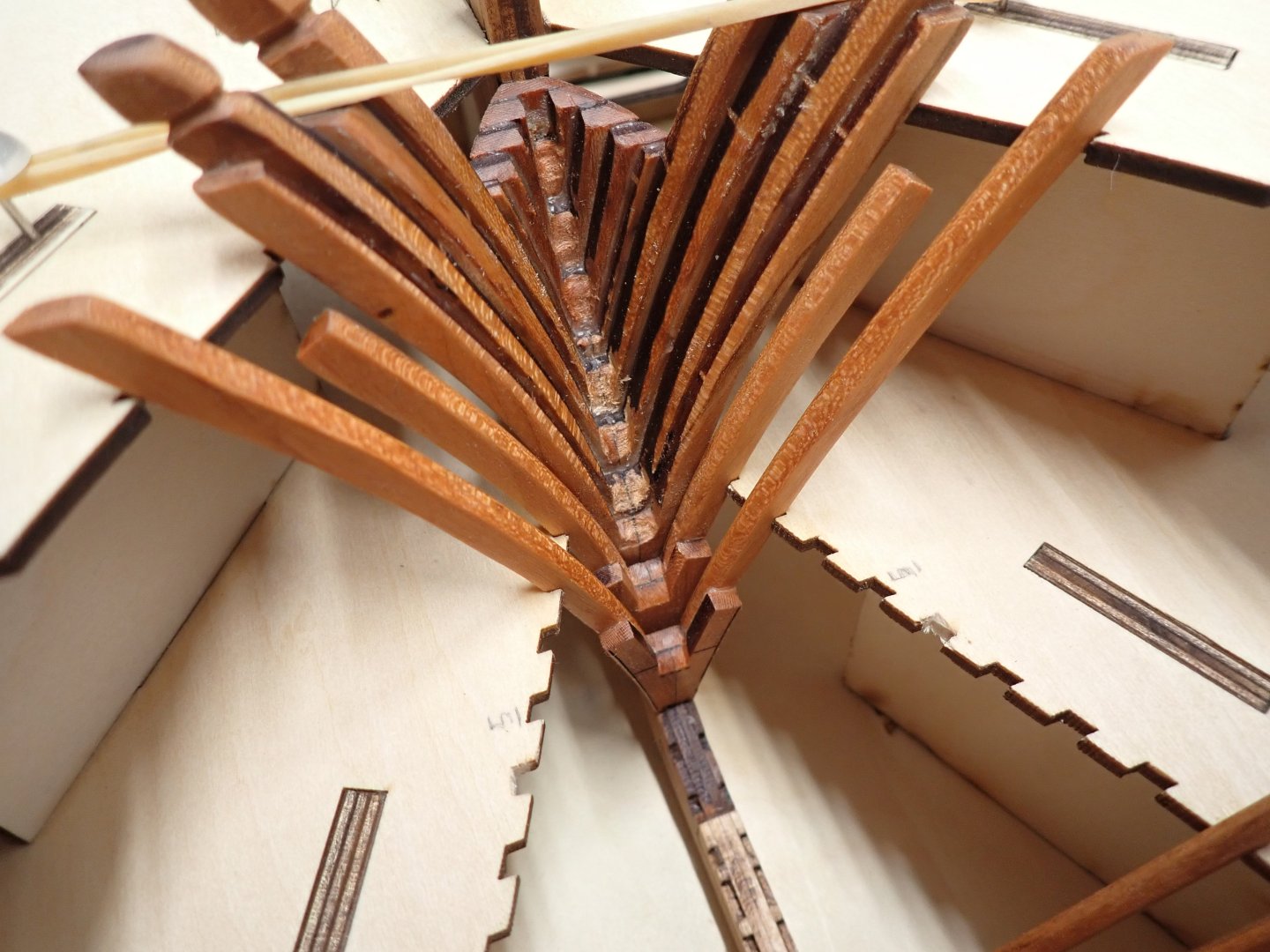
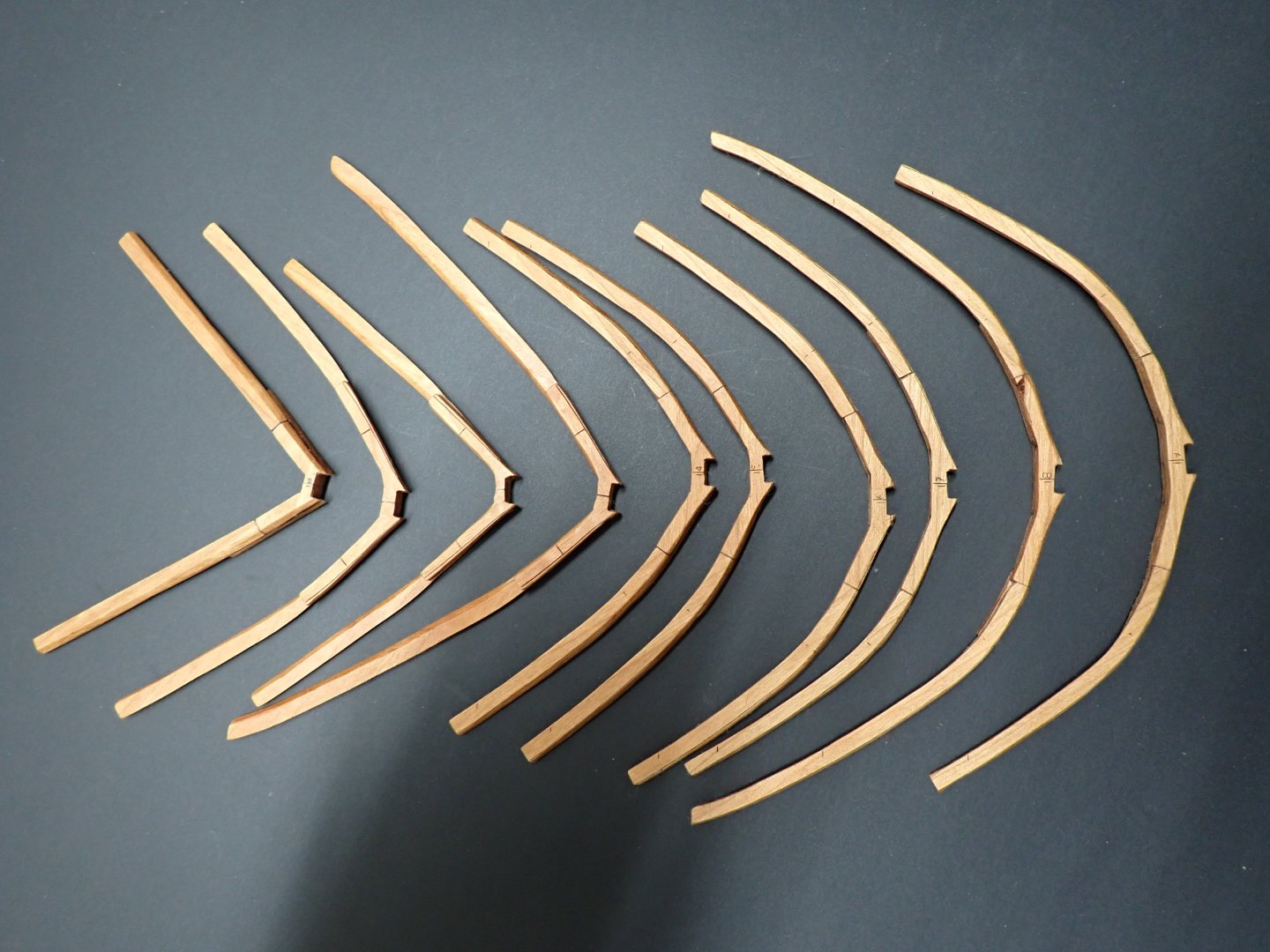
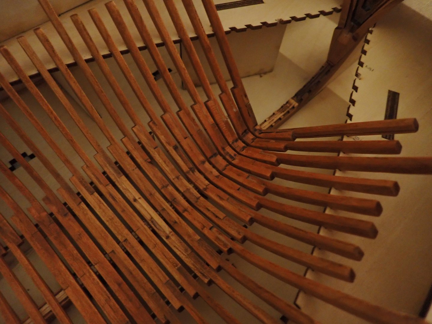
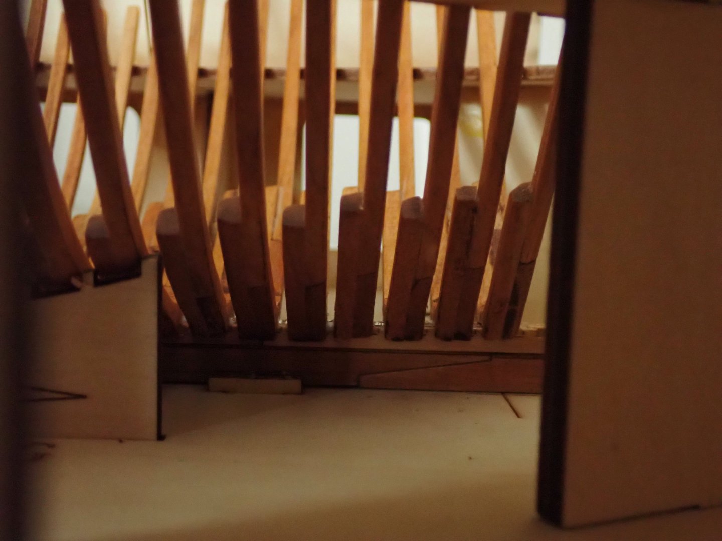
Frames #2 to #9 have been built. They are by far, the most difficult and delicate to install. There is a lot of sanding that takes place to fair them externally and internally and the insertion on the keel requires a lot of delicate sanding and numerous attempts. The CAF Model kit is very close to the Monograph and did not take the short cuts seen on the ZHL kits, which simply place each frame in a slot. The picture below shows what I mean: The frames are ready to install. Because of the severely restricted space, you need to build one frame at a time and make sure it fits perfectly. No gluing must take place at this stage. Then, when all frames are ready, I find it easier to glue #2 first and go to #9, one at a time. Above, Frames #2 and #3 have been glued. I use CA glue, since it is not practical to use Titebond at this location. Above, three more frames to go..... And it is over for the front: At this stage, a good half of the frames have been installed (#1 to #50). We will encounter some difficult frames again, when moving to the stern. Yves


- 185 replies
-
- 26
-
-
Frames #10 to #19 are now completed: Dry-fitting first: One frame is not exactly aligned with the rest.... #17. It will comply later on.... Finally, we pull the tube of glue (Titebond): Next will be Frames #9 to #1.... The most difficult ones !!! Happy Thanksgiving everyone. Yves


- 185 replies
-
- 16
-
-
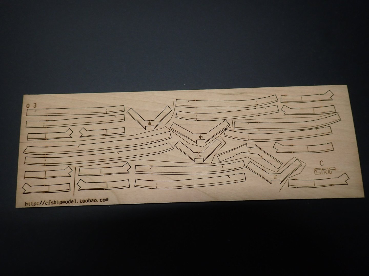
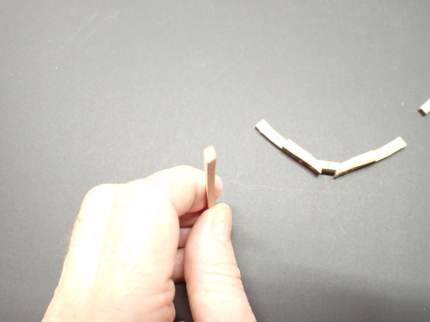
Since there were some interests and concerns about building the frames, here is the step by step approach I am taking. Let's focus on Frame #15, which is one of the delicate and more complicated to build: After removing the five pieces that make #15, the following central parts are glued: The long ribs are then carefully sanded using a Dremel, a semi-round file and some sandpaper: The center piece (there must be a technical term for that...) is not touched yet, besides sanding and opening the slot to make sure it fits on the keel, smoothly but tightly. Fairing of the long ribs must be done on the external side and also on the internal side. Thinking and visualizing how the ribs will fit is paramount. Then glue (Titebond will give you time to adjust the parts in situ) the two long ribs to the center piece and place it in the jig, on the keel: You can see that the fairing done on the outside, allows the frame to fit perfectly in the jig. Small clamps are used to hold the parts during drying. Lots of verification to make sure that everything fits nicely. When dry, remove the frame from the jig: Now is the time to sand and polish the center part. When done, another verification in situ: The frame can now be oiled and waxed, using my favorite Howard mixture: Once all the lints has been removed and when the part is dry, it can be inserted back into the jig, before the final gluing to the keel: Now, redo the same for Frame #14. Yves


- 185 replies
-
- 17
-
-
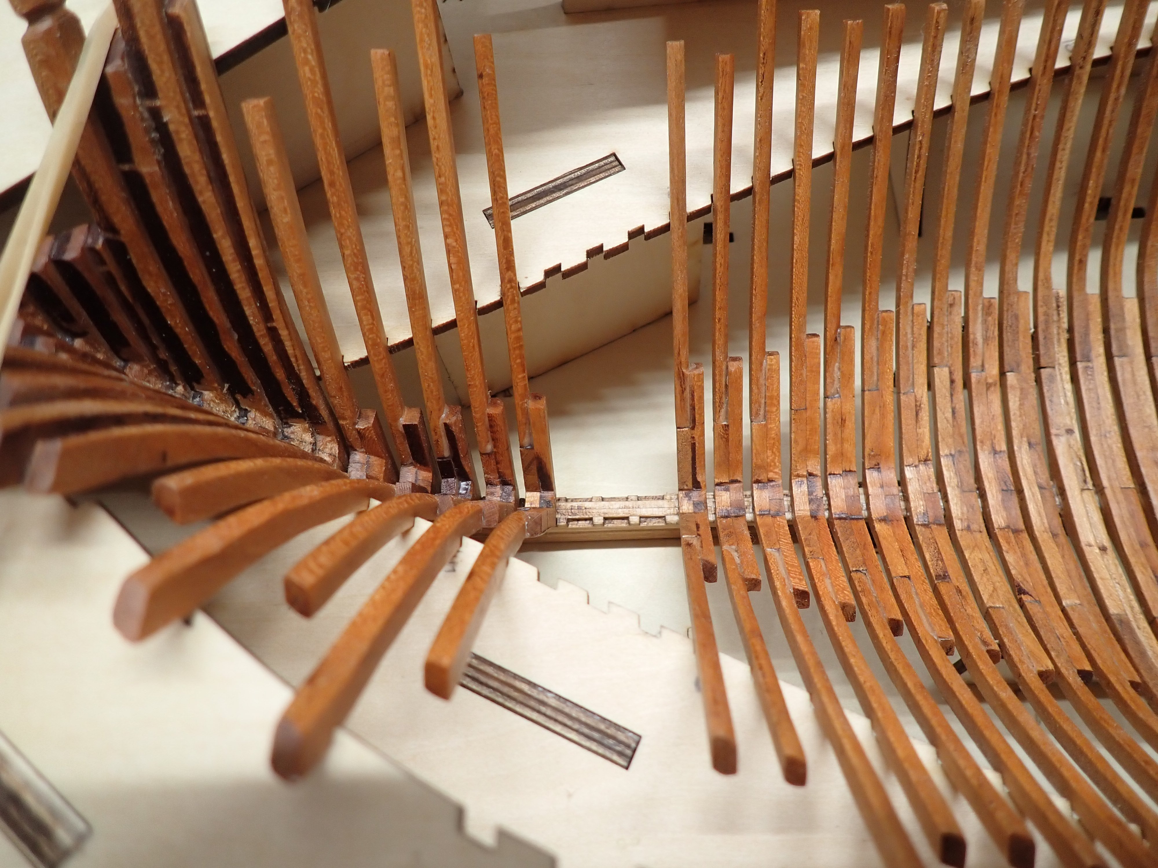
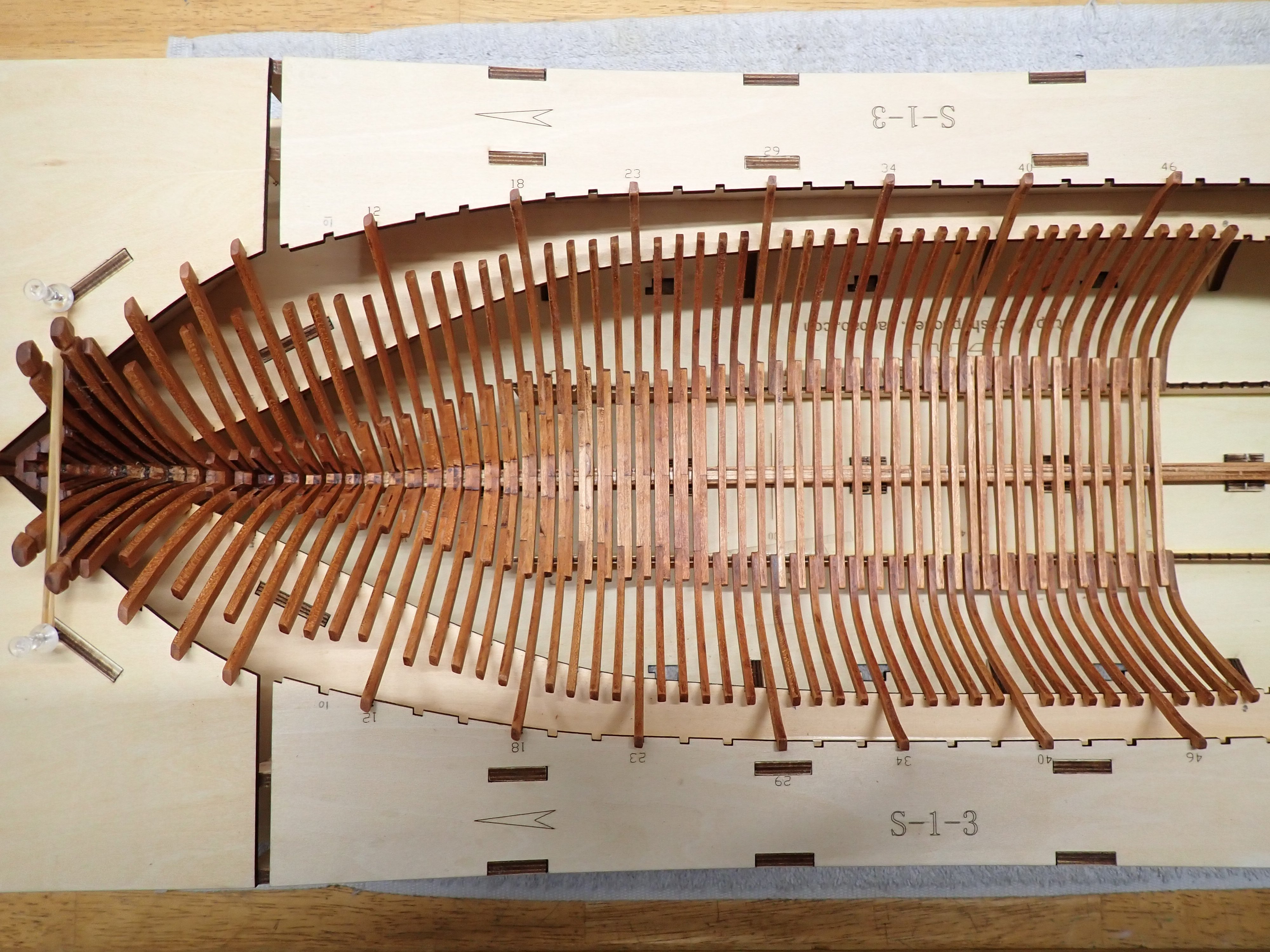
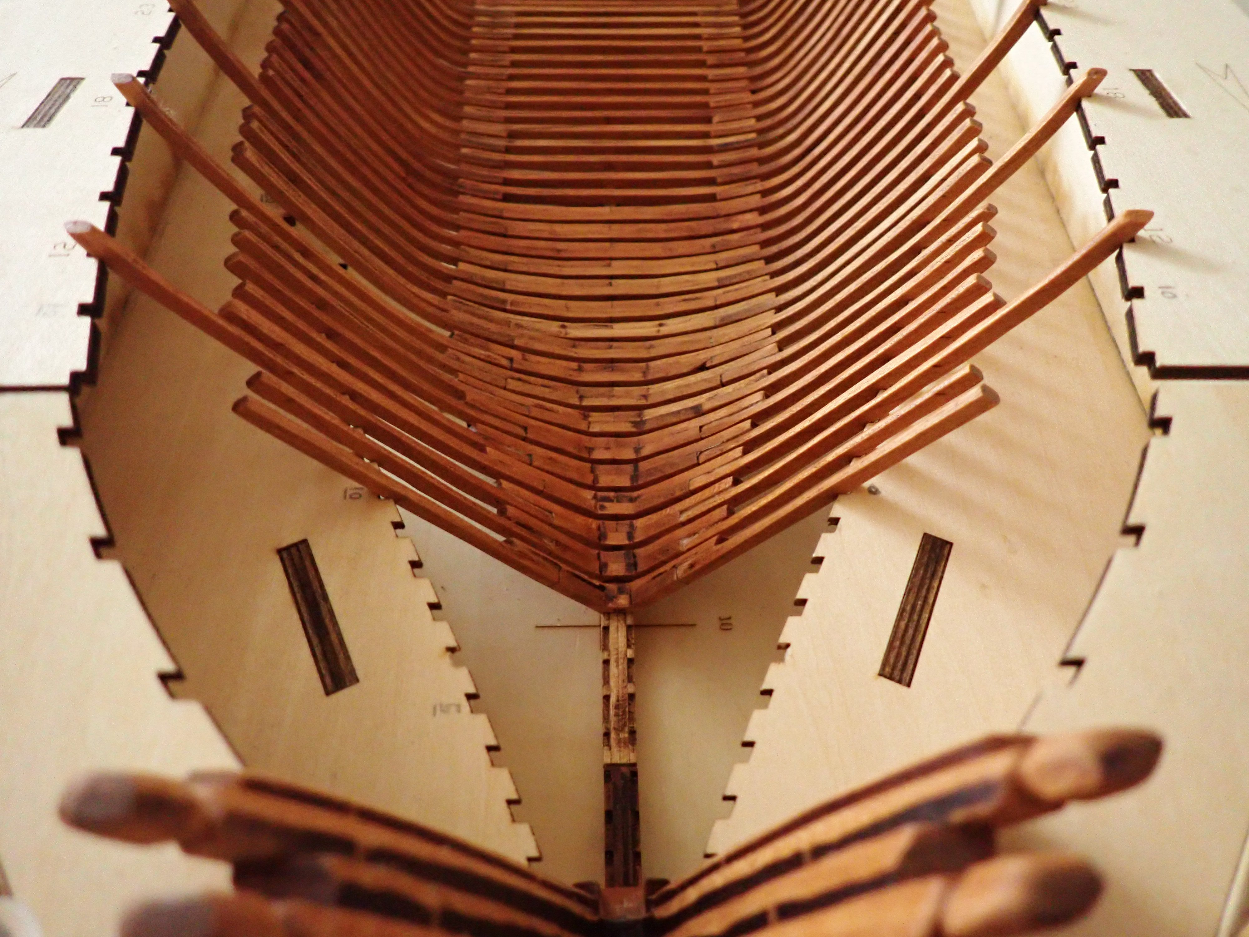
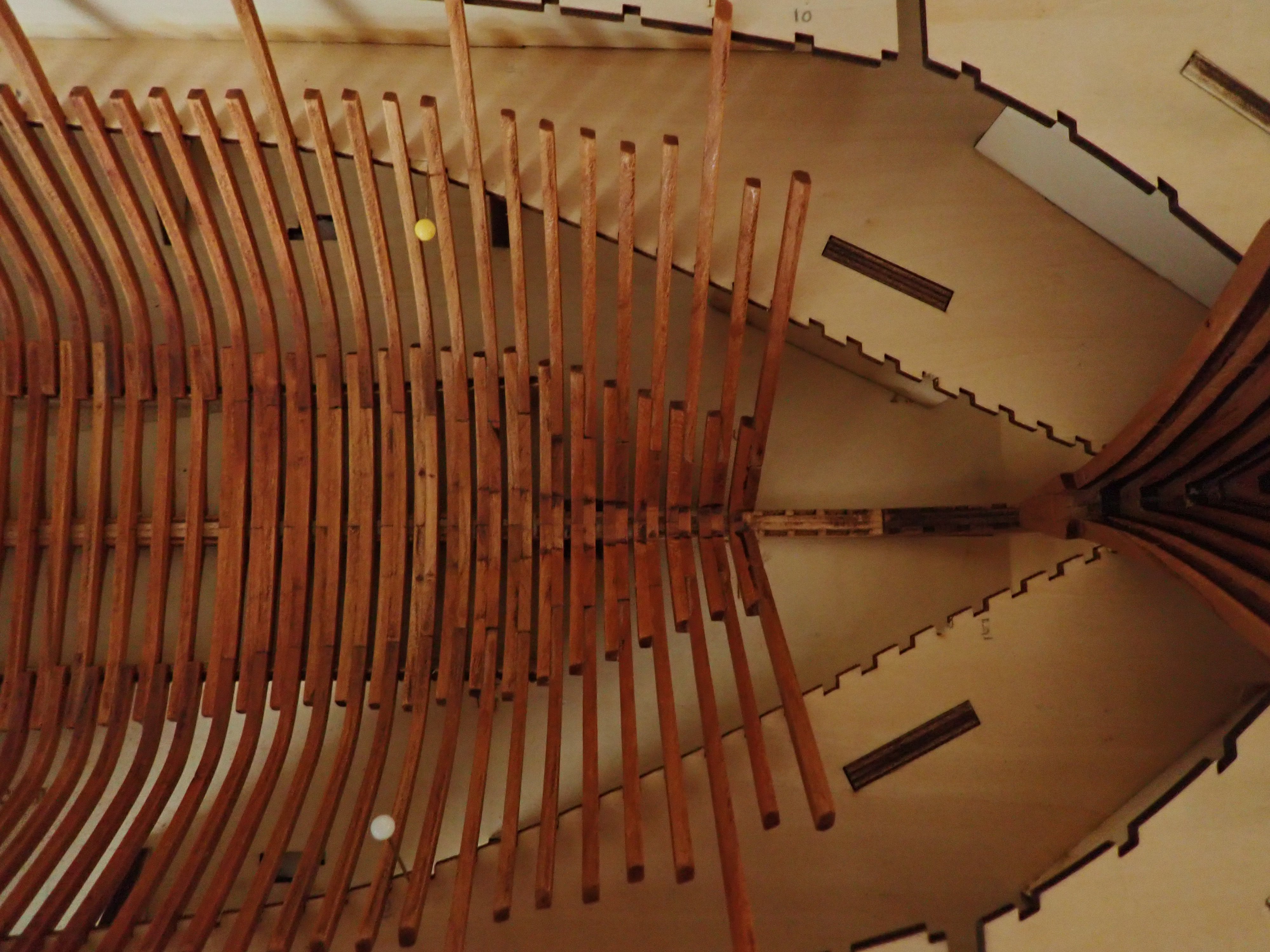
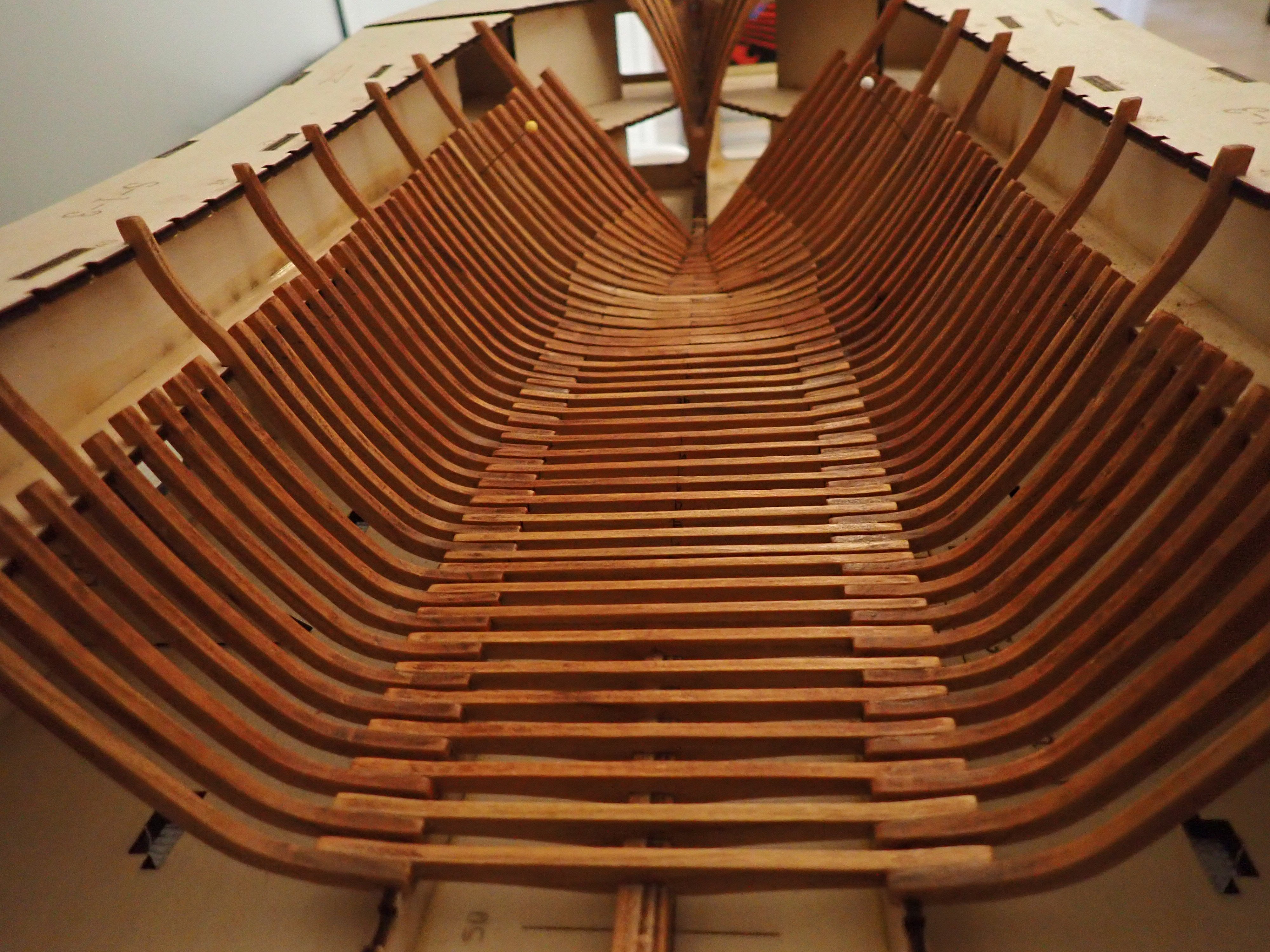
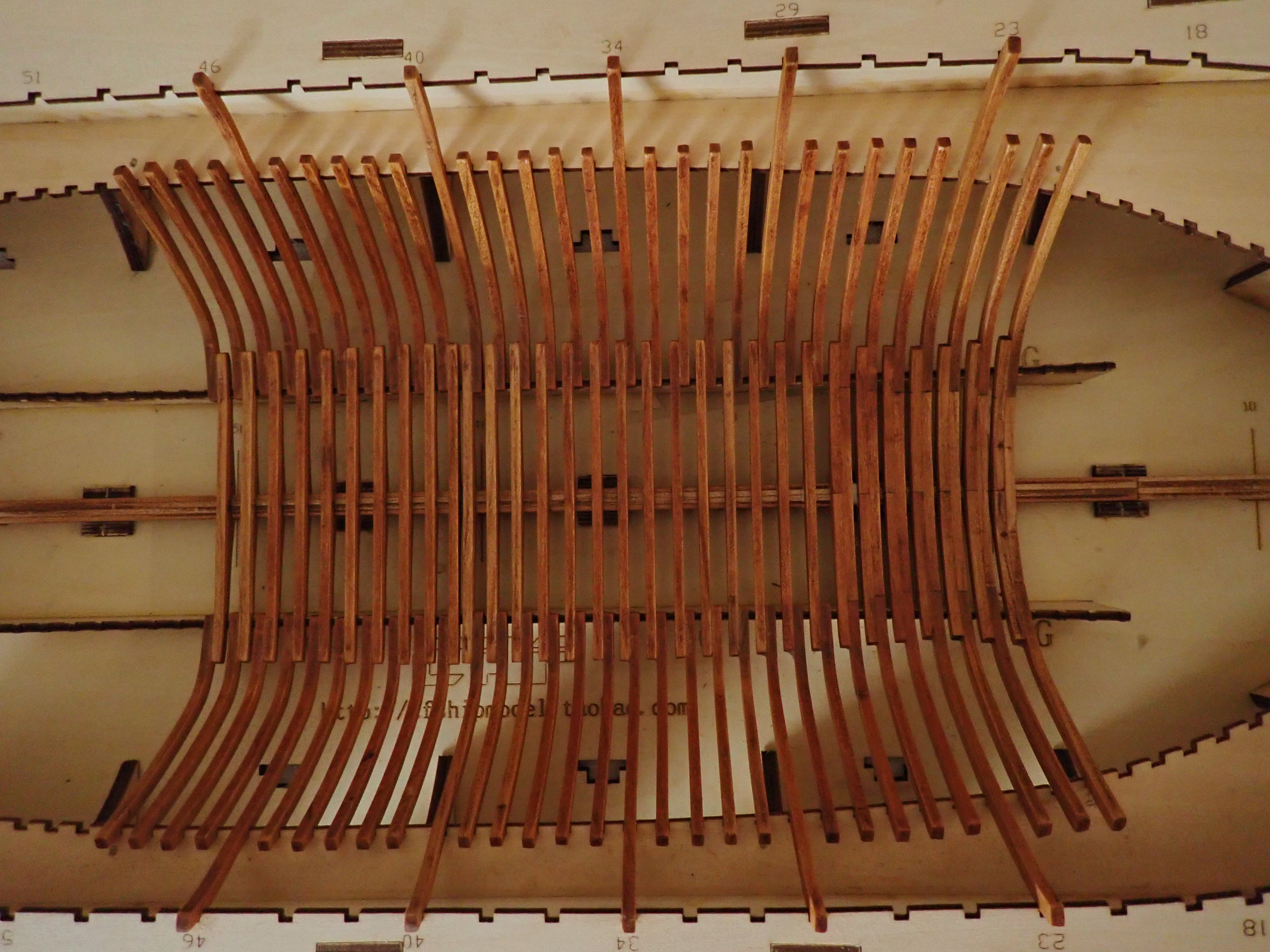
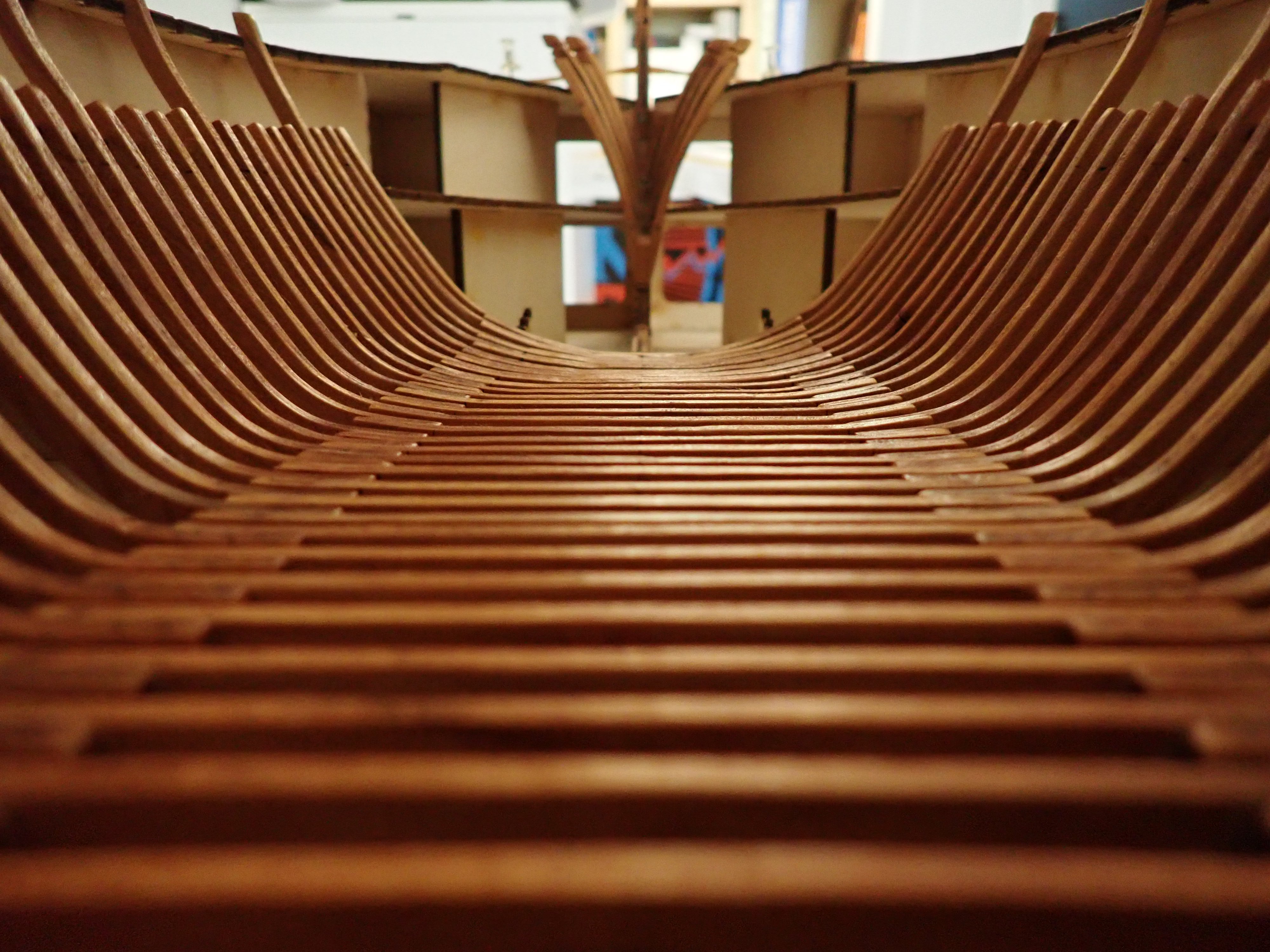
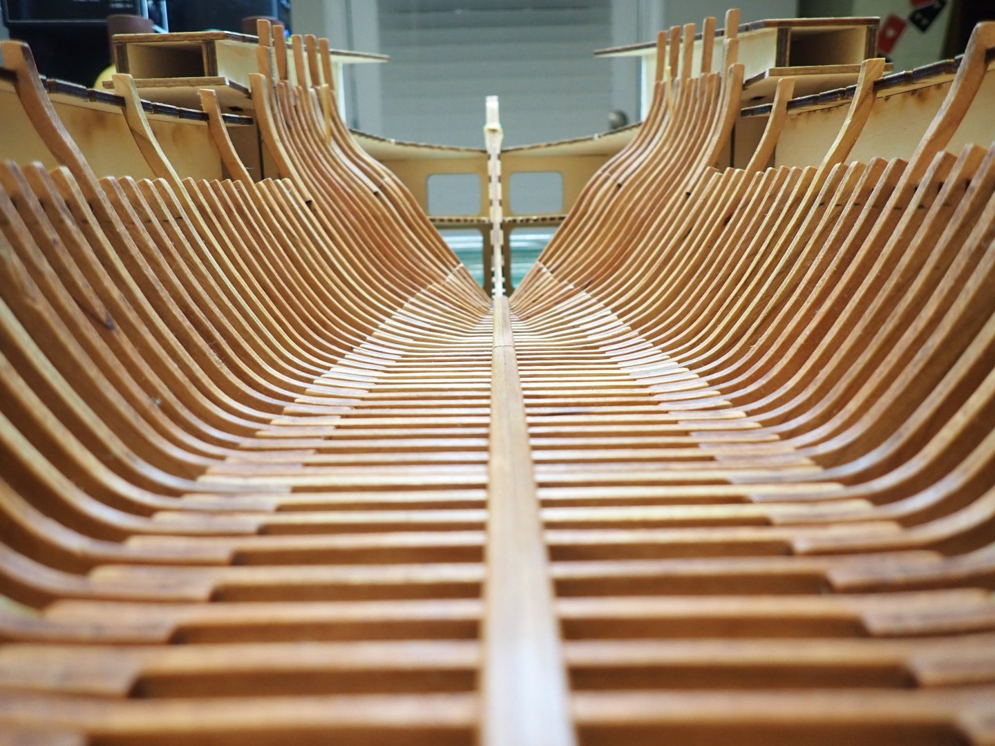
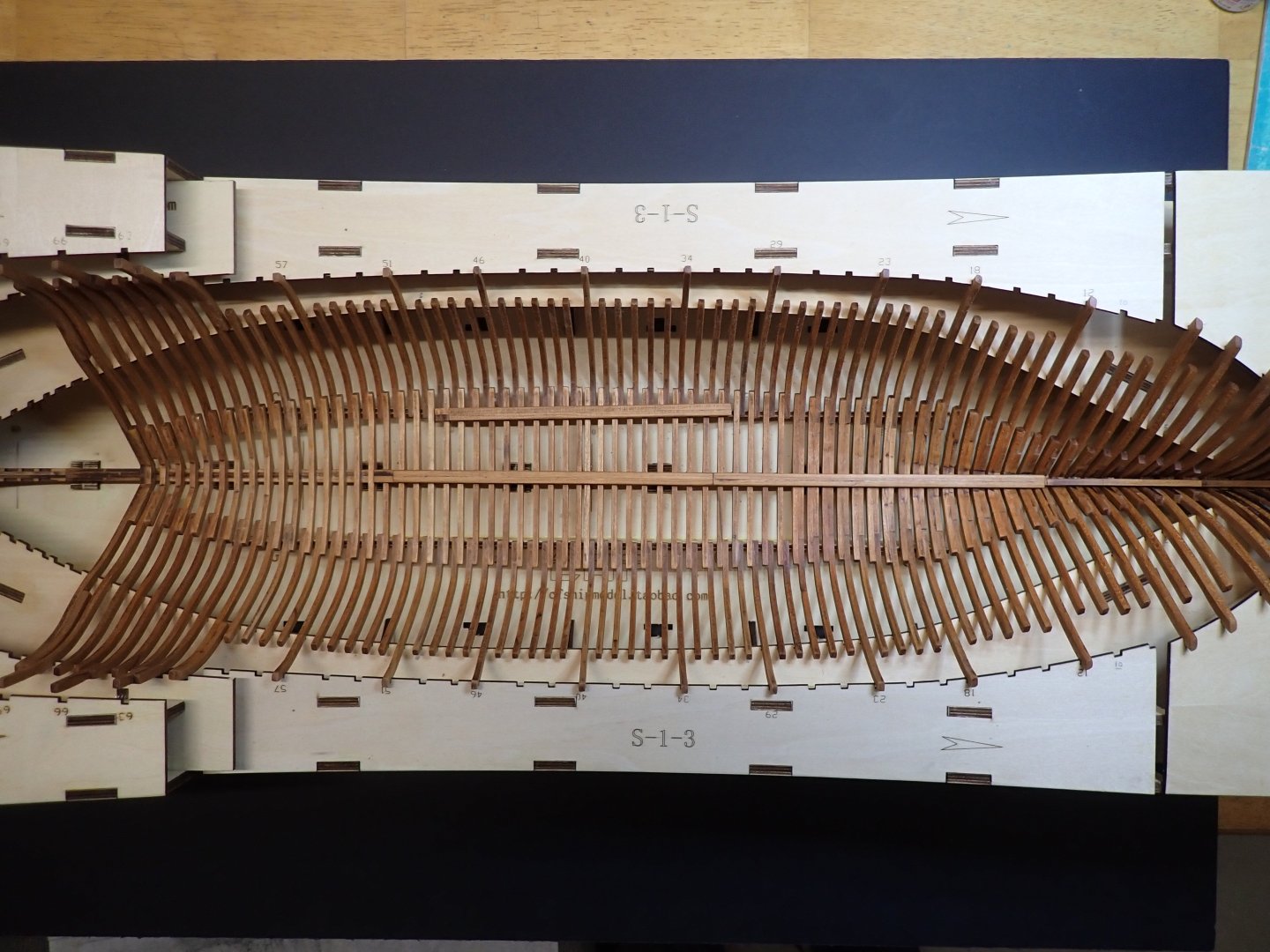
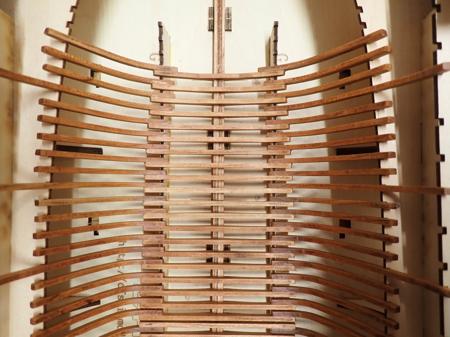
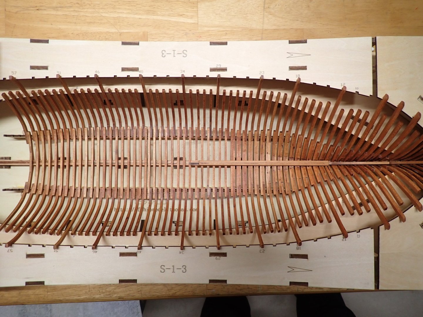
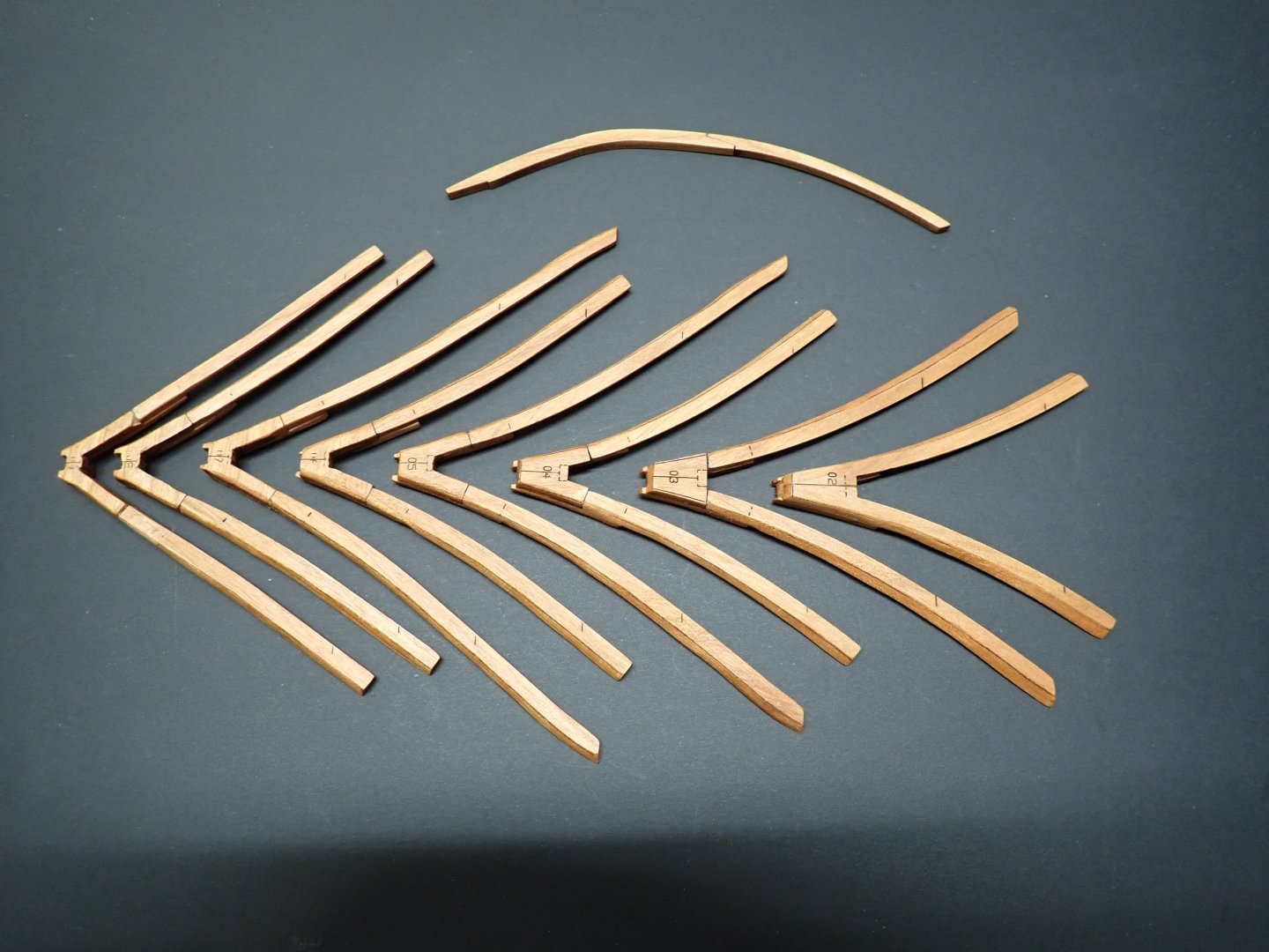
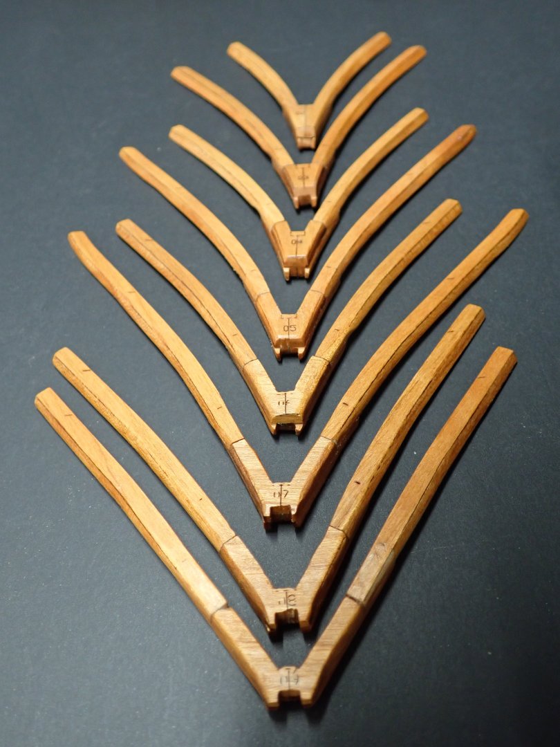
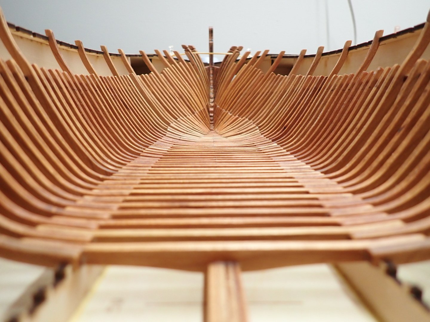
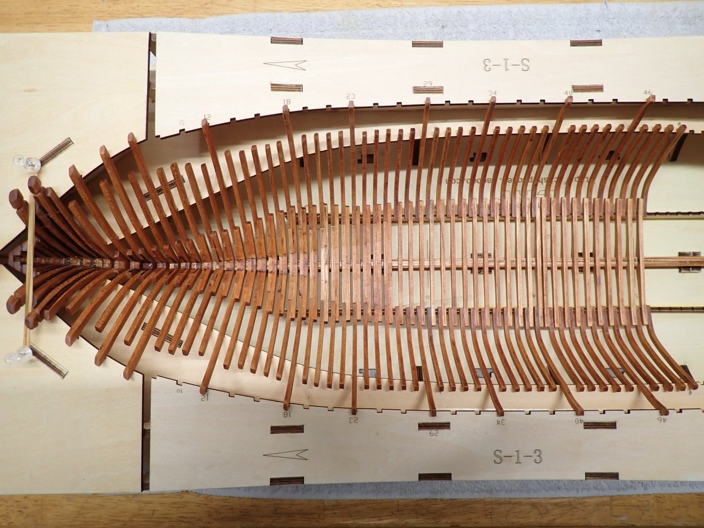
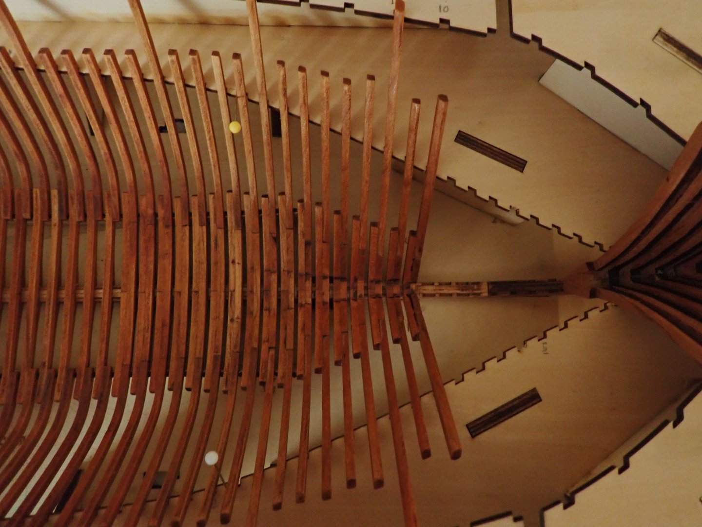
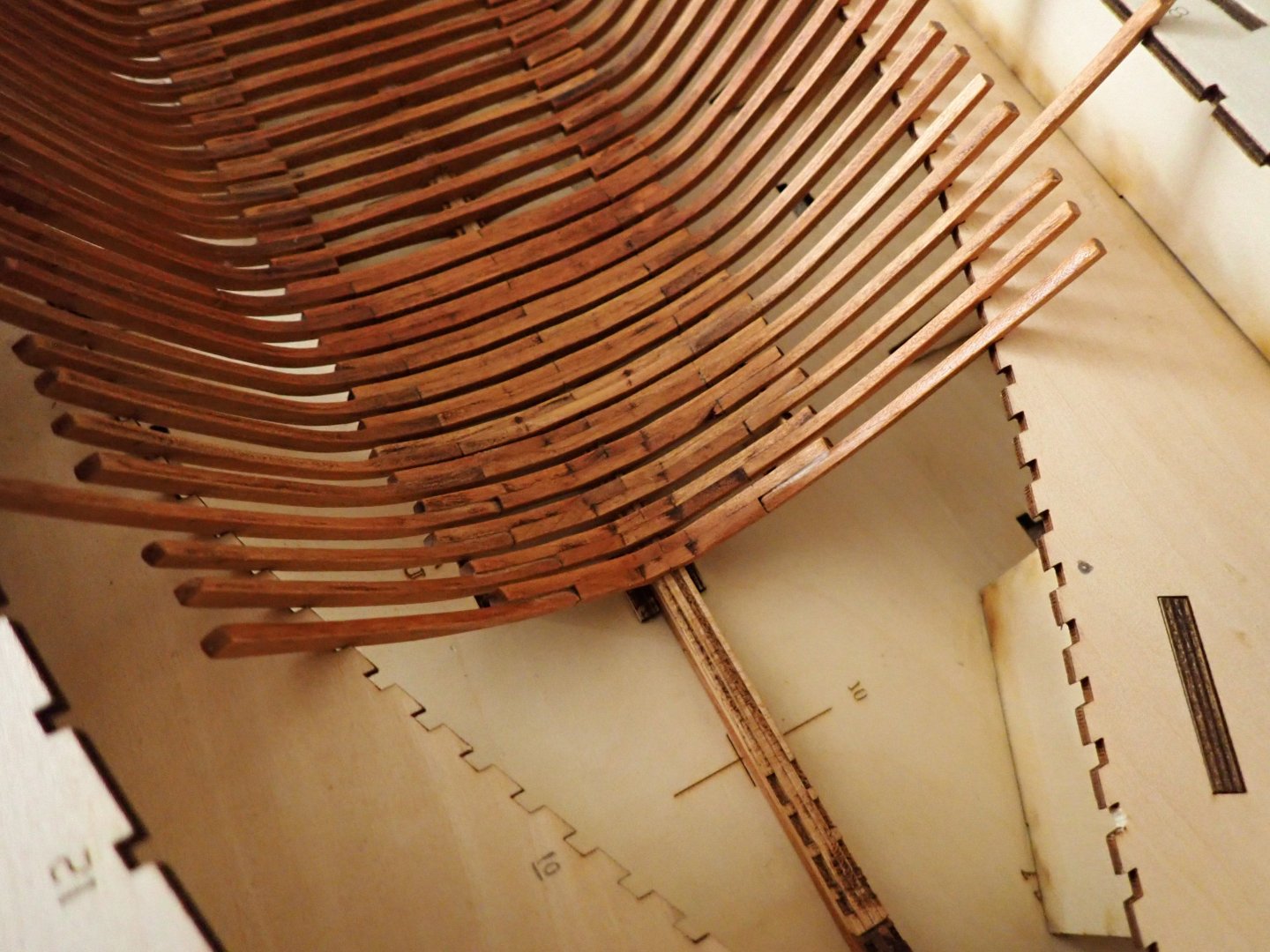
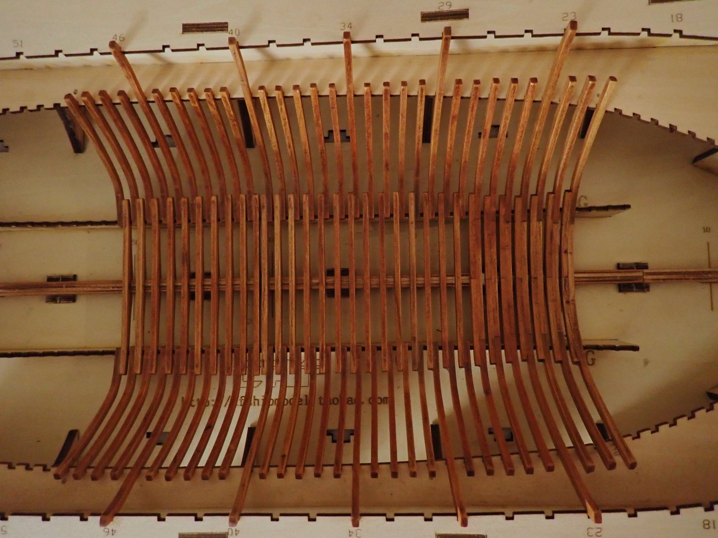
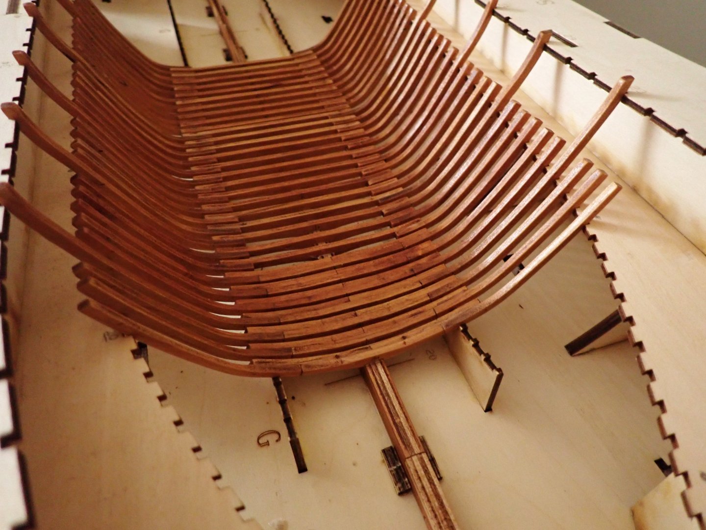
Frames #20 to #29 have been completed and glued to the keel: It looks more and more like the skeleton of a large fish. Frames as depicted, have been oiled and waxed. I have about done one third of all the frames. Next will be the #10 to #19 series.... Yves


- 185 replies
-
- 15
-
-
Chuck, where are you moving? Are you getting a house with more utility space for your business? Yves
-
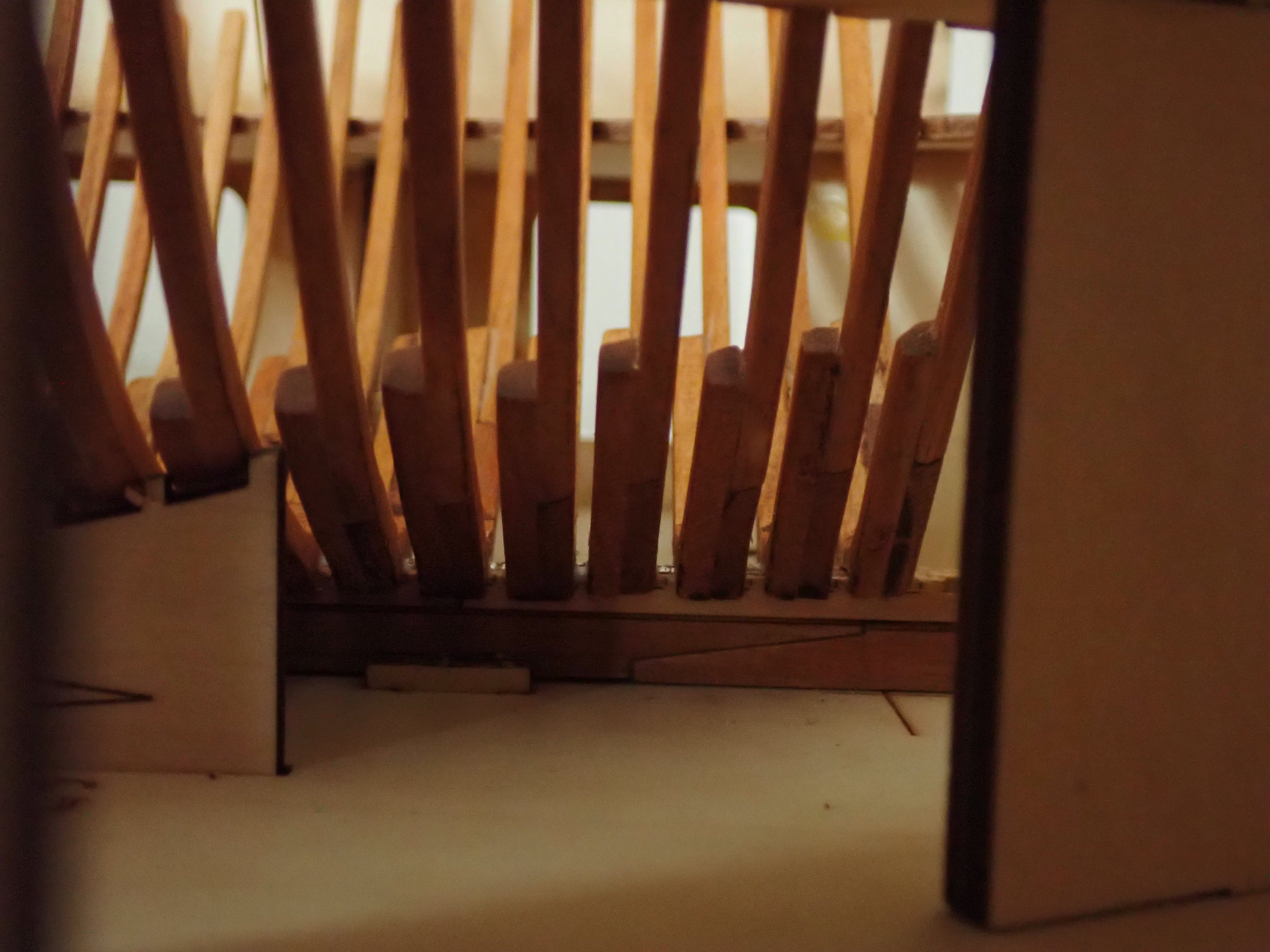
You really have to sand the ribs as much as possible, before inserting them in the building jig. Multiple reasons for that: Fairing internally and externally must be done ahead of time, because the internal planking will be glued when the hull is inside the jig. For the frames to be extracted from the jig, they must be slightly smaller/less thick and well polished/sanded so that they can slide out without breaking. I noticed that oiling and waxing them before gluing them, helps tremendously. I still suspect that extracting the spine and frames from the jig is going to be nerve wracking. I think I will insert some kind of crowbar from below and push up the keel very gently. Right now, with about 30 frames in, it is still possible to move it a tad. Finally, the hull is not planked on the outside, with the exception of a plank or two. The goal is to show the skeleton of the ship. I need to check with Tom, when is the ideal and safest step to take the hull out of the jig. This is not clear in the instructions. Yves