HOLIDAY DONATION DRIVE - SUPPORT MSW - DO YOUR PART TO KEEP THIS GREAT FORUM GOING! (Only 75 donations so far out of 49,000 members - C'mon guys!)
×


yvesvidal
-
Posts
3,607 -
Joined
-
Last visited
Content Type
Profiles
Forums
Gallery
Events
Everything posted by yvesvidal
-
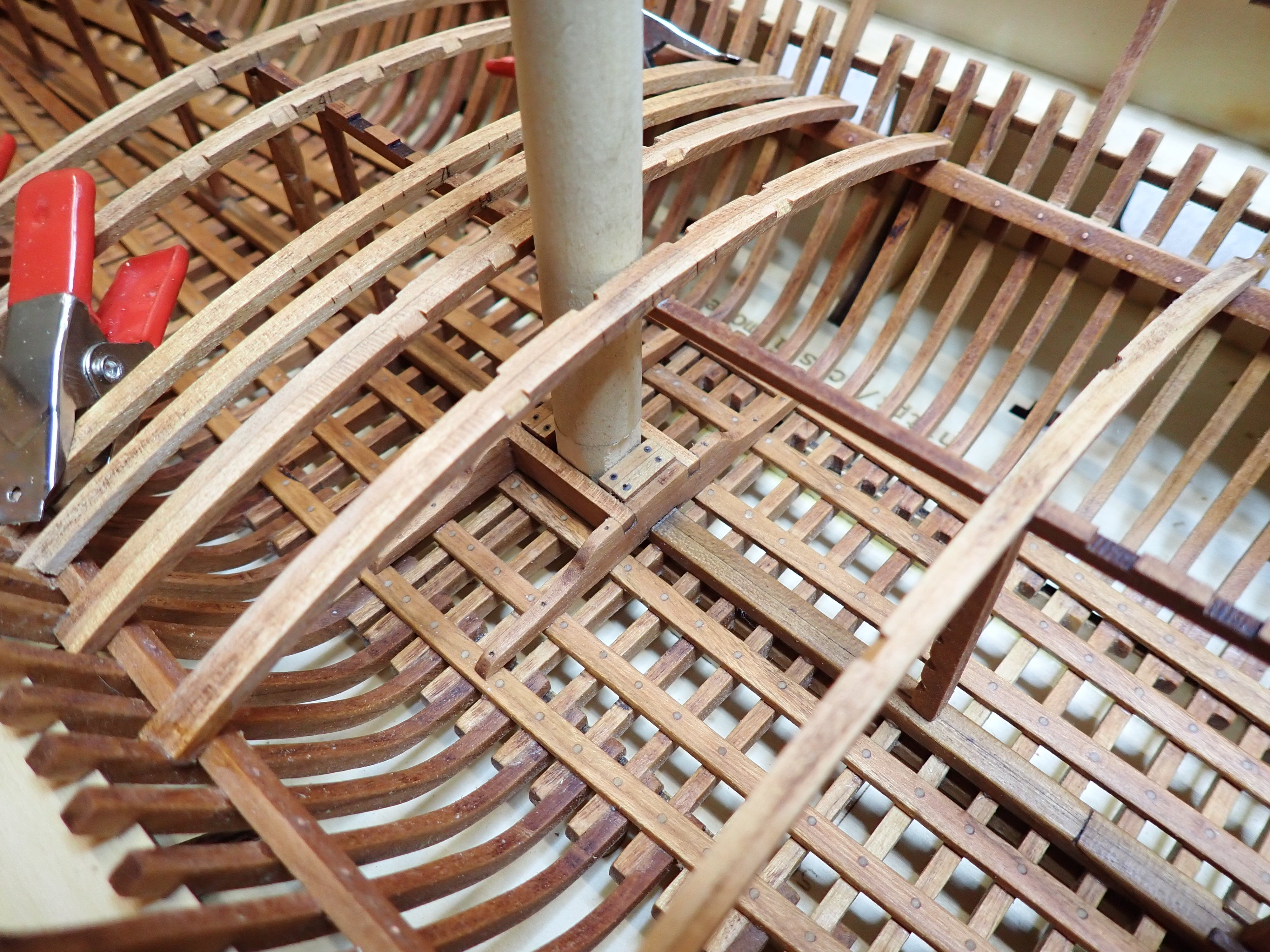
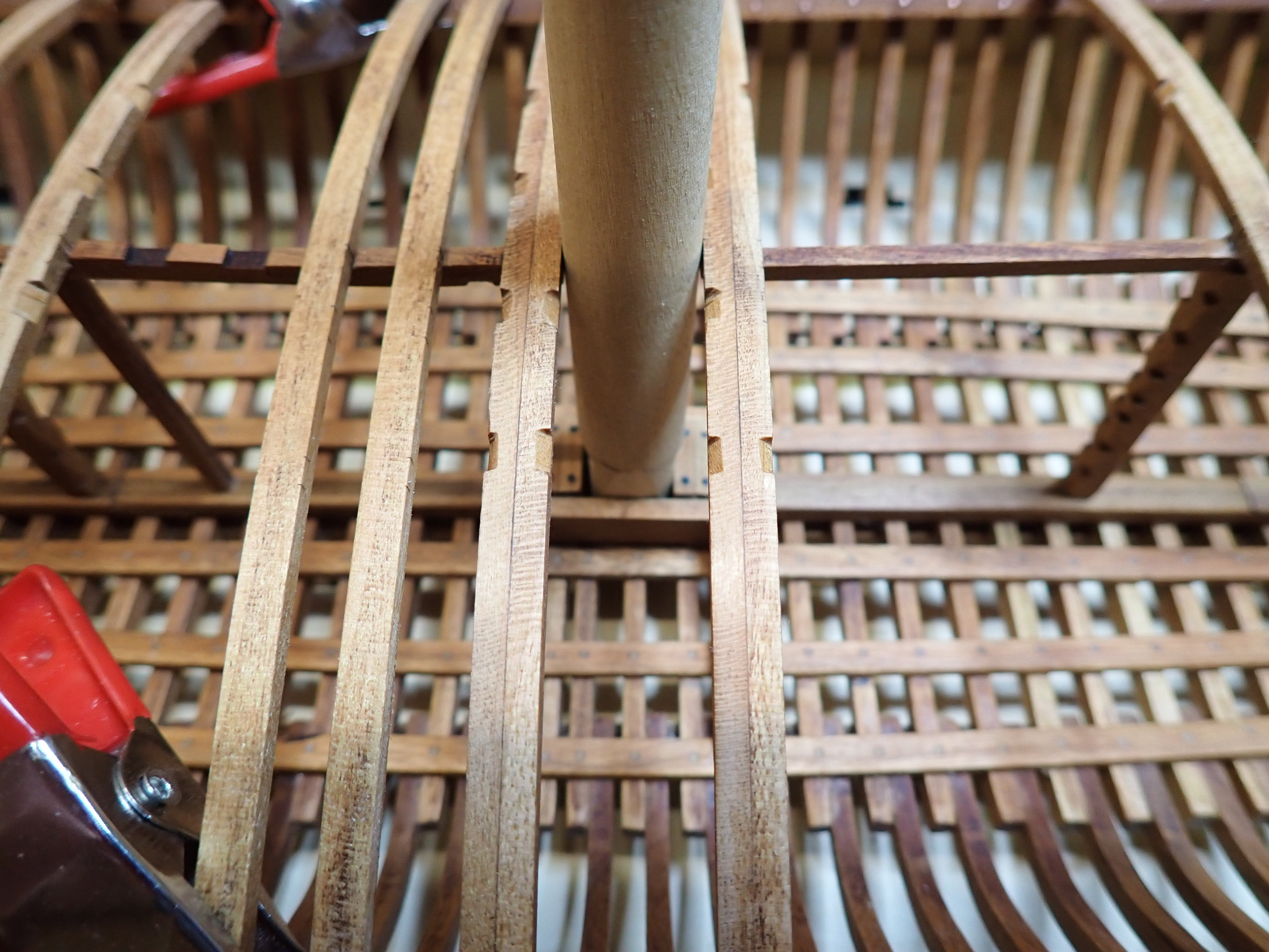
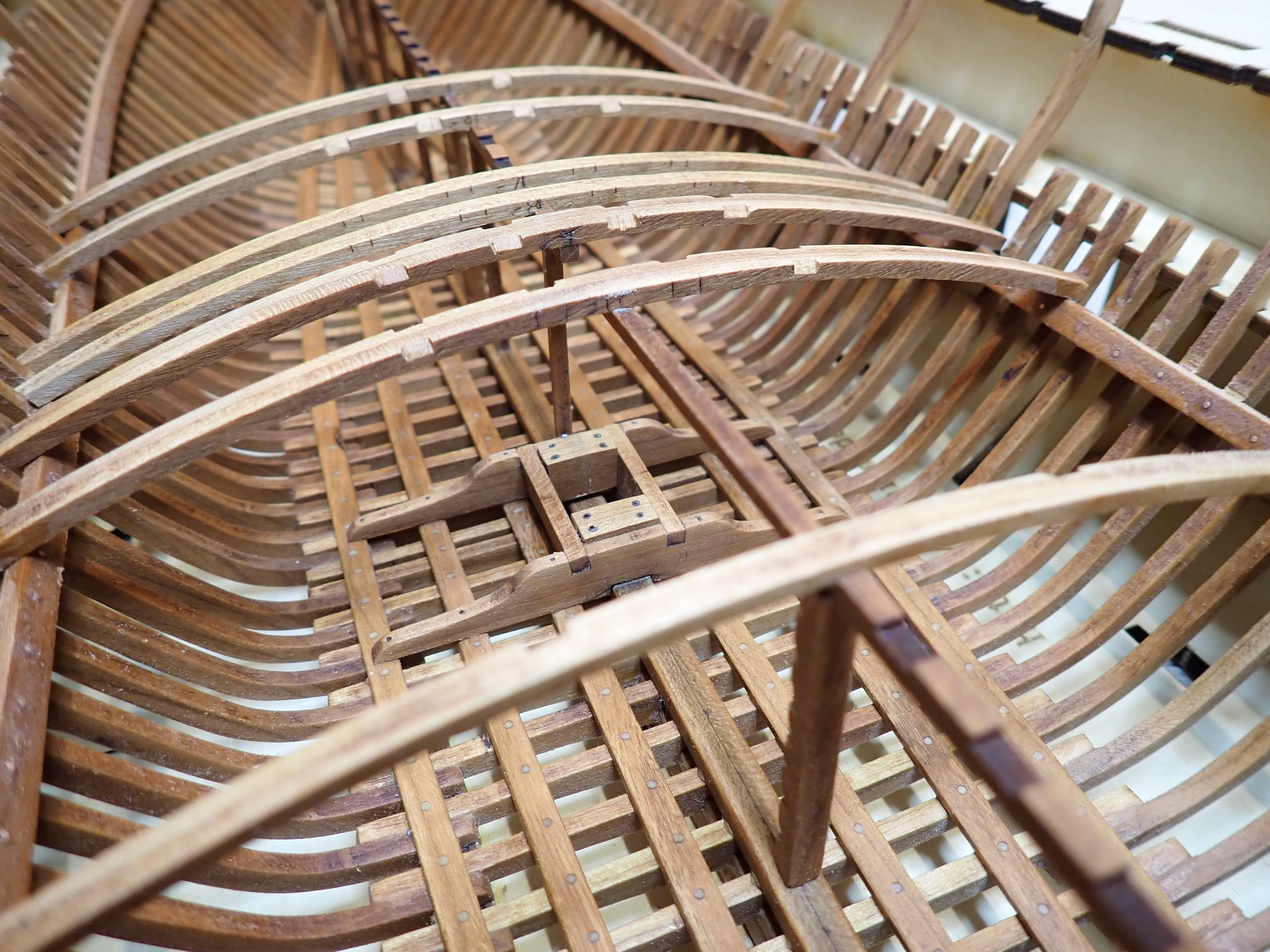
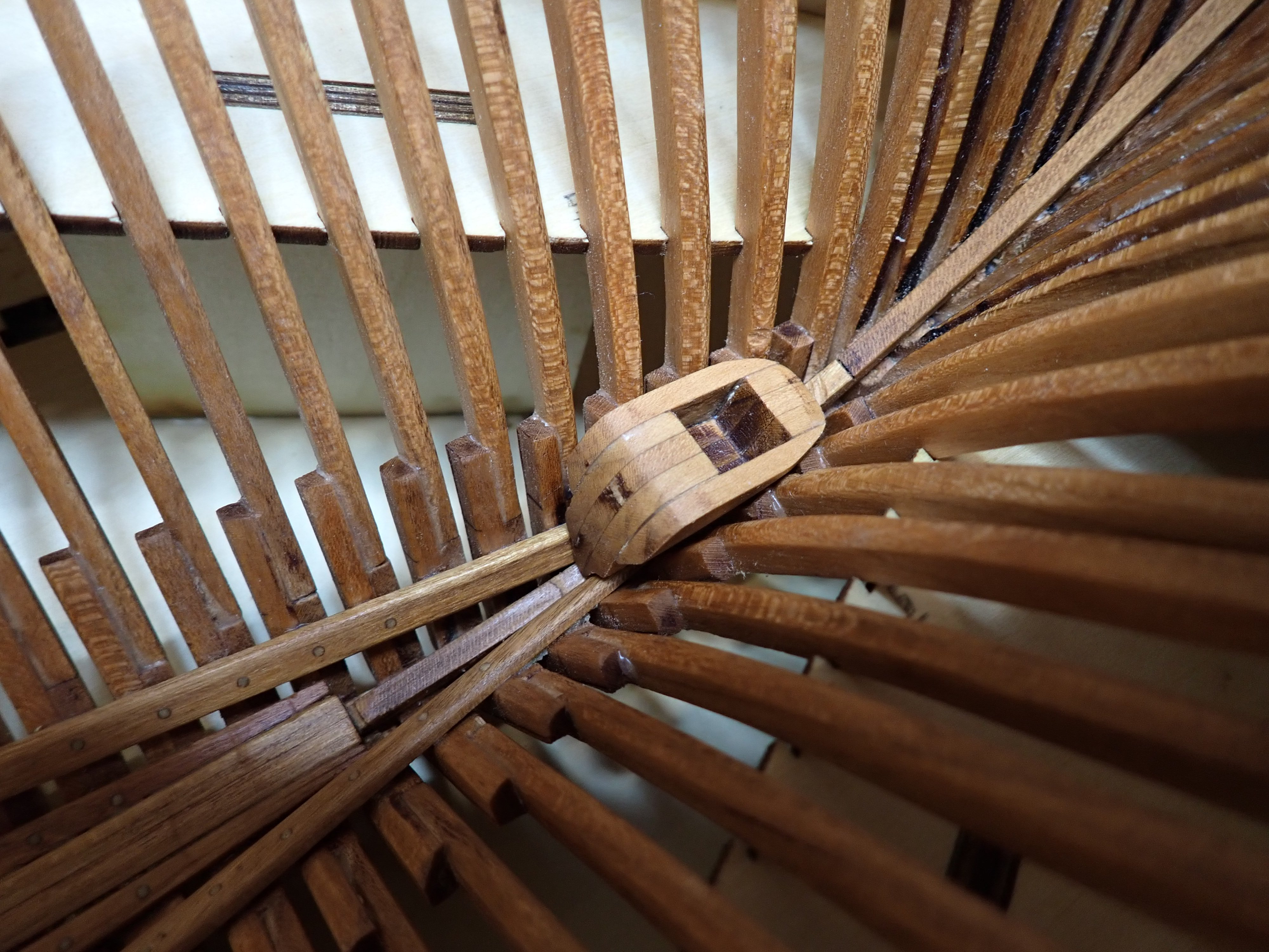
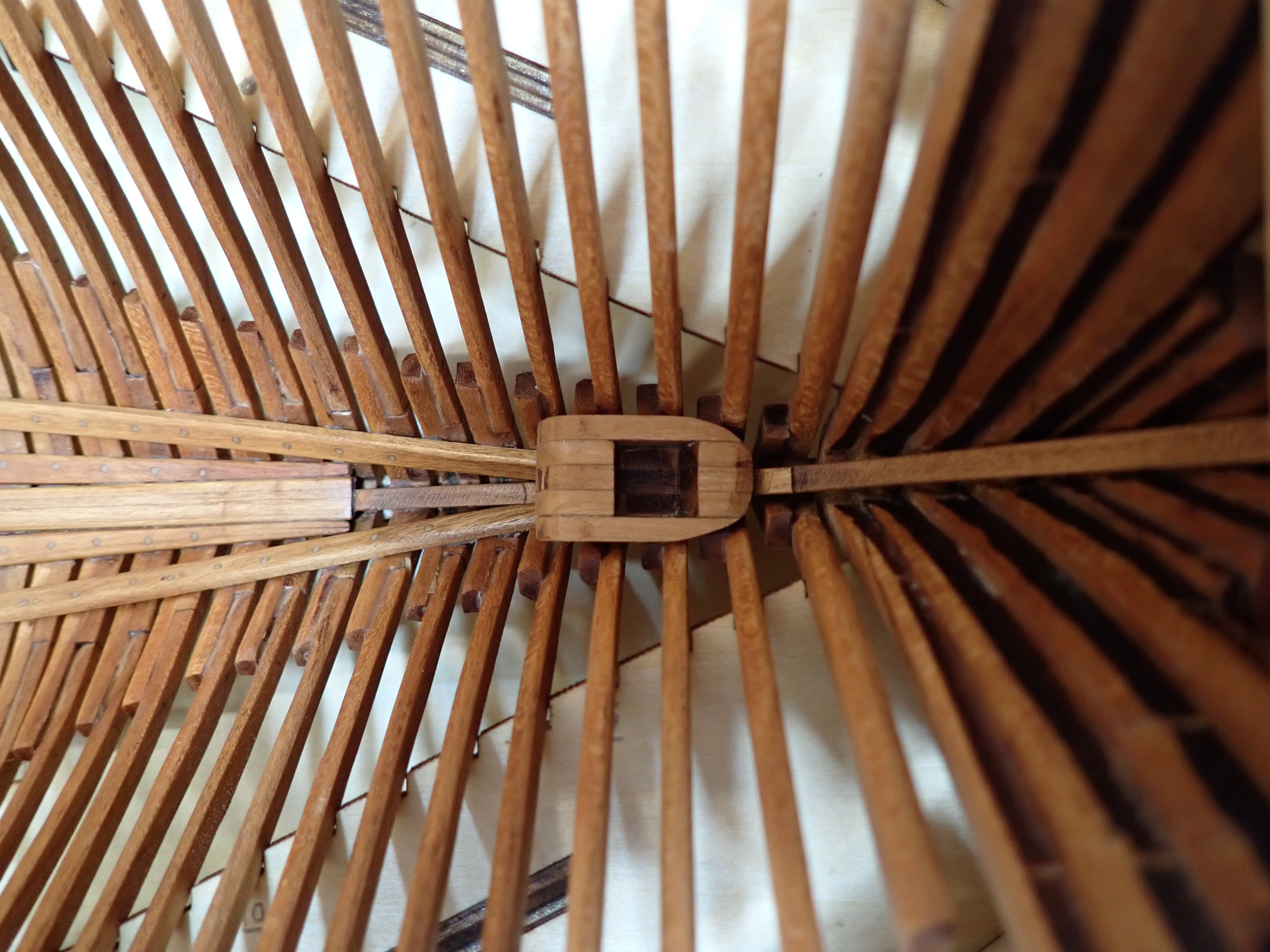
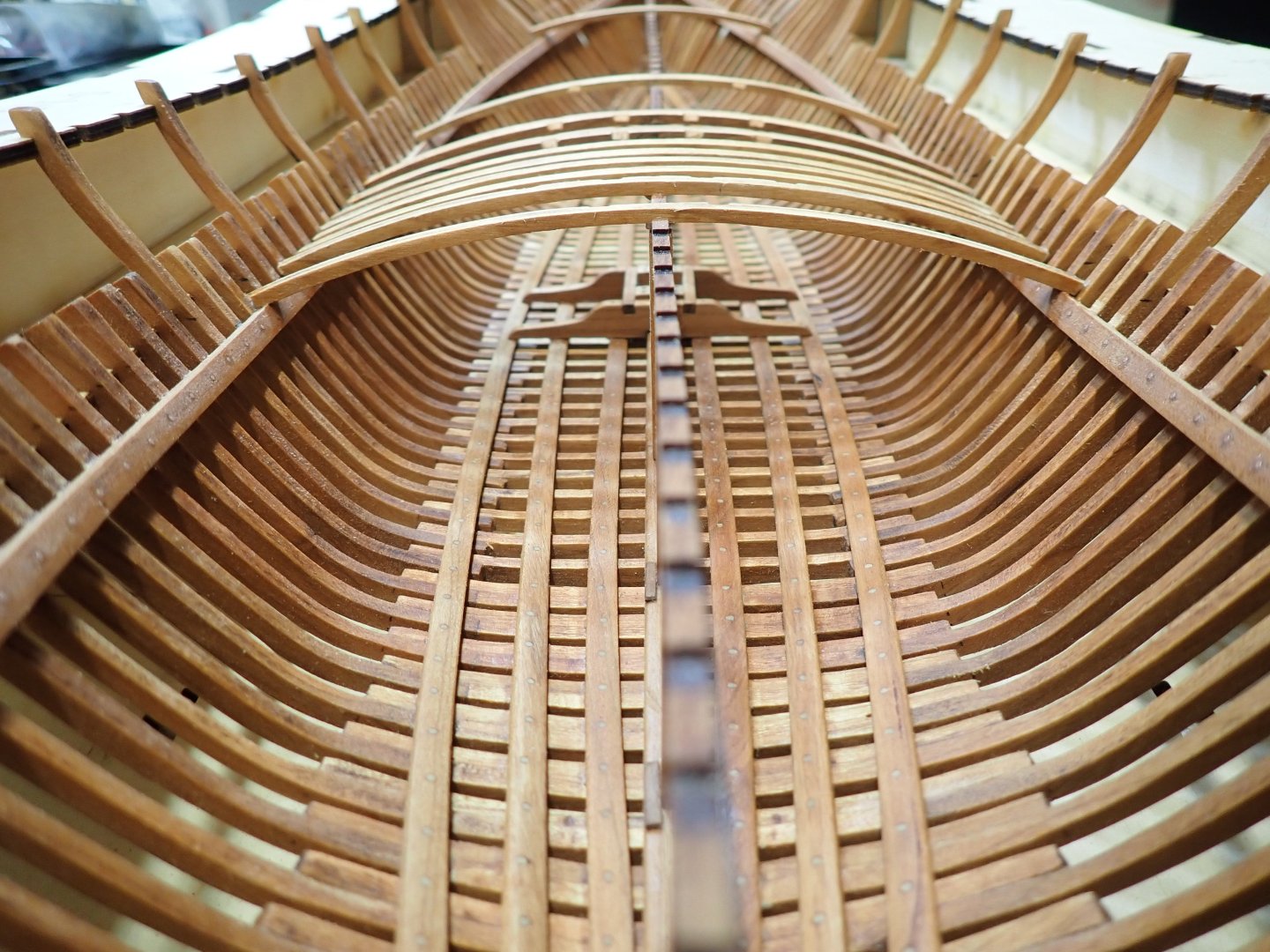
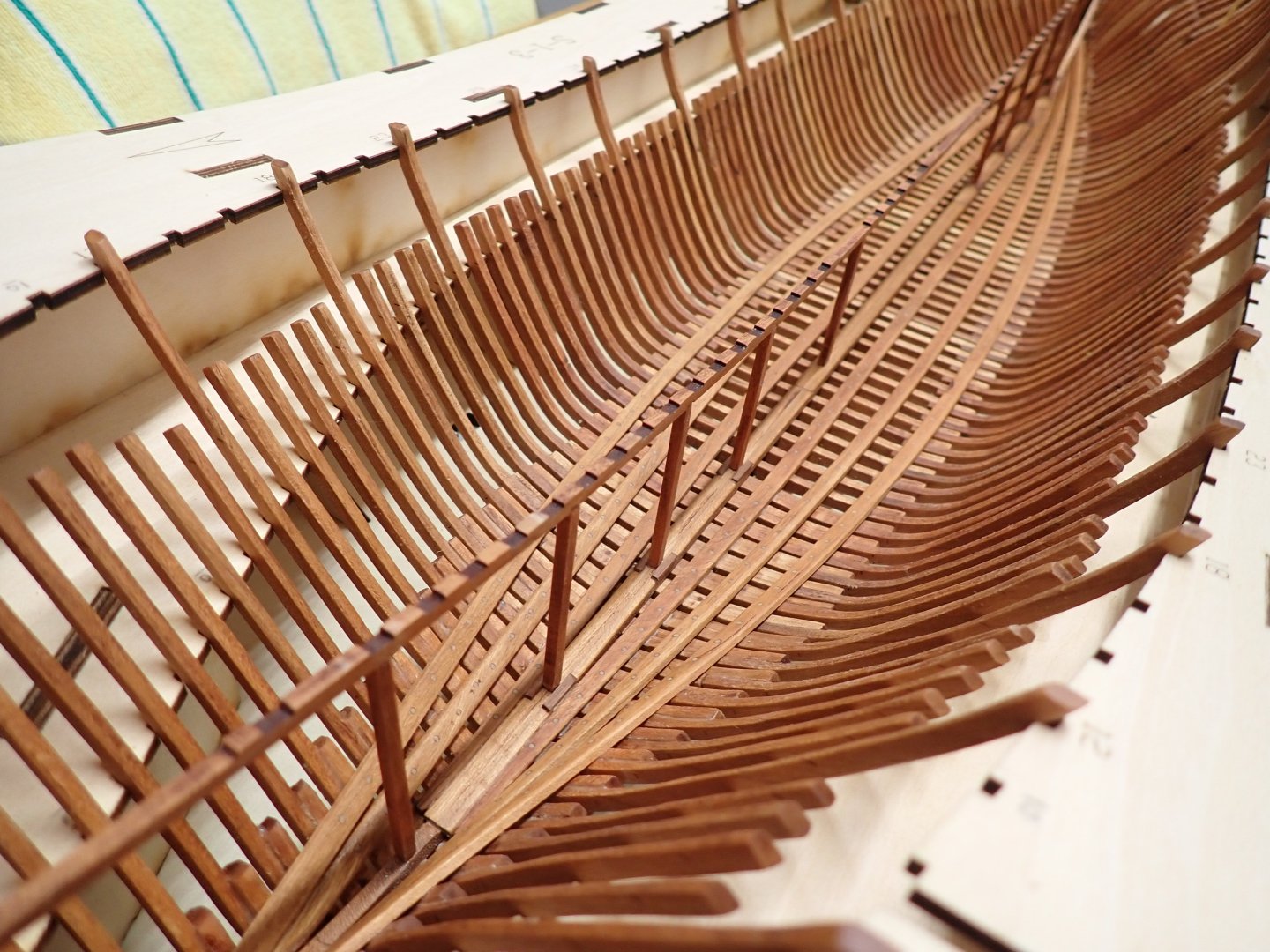
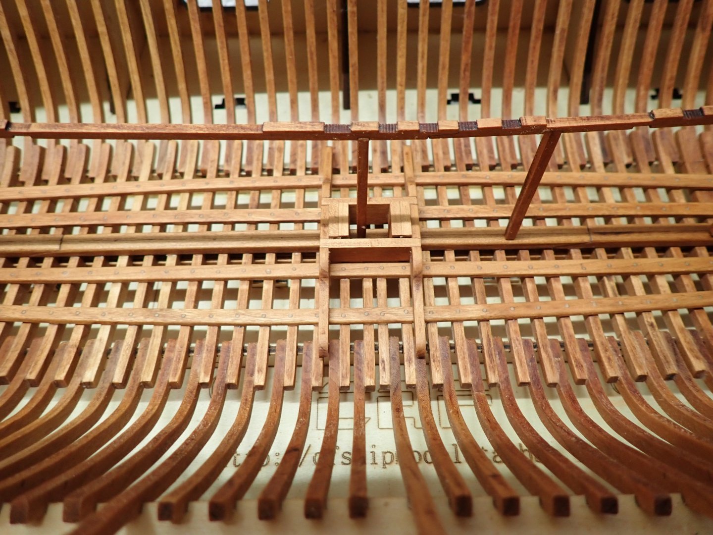
 I am moving along with the installation of the deck beams and the main mast base. On the picture (above), you can see that the central support has been carefully cut to allow the main mast to be installed. Before cutting, I installed on each side a few more beams to secure the central support. I did not want it to collapse or buckle in any ways. The main mast fits just right. It is 15 mm in diameter and will probably be slightly reduced when sanded to shape. After carefully eyeballing the mast to be perpendicular, the mast base can be positioned and glued (See above). Gluing more deck beams, after sanding slightly the waxed wood and using exclusively CA glue. A vertical support piece has been added next to the base, according to the Kit plan and Monograph (above). I know, it is a lot of beams.... Next, I will be doing the same with the front mast. Stay tuned. Yves


- 185 replies
-
- 15
-

-
Brian, Regarding your question about the interior of the hull, I have been pondering whether I should show some of the deck beams open (not planked), since the hull will not be planked to display the numerous frames. However, I tend to go with a full planking of the deck as there are a lot of things to install and display on the deck. Leaving a section of the deck un-planked, would restrict the amount of stuff that can be installed on it. In addition, the model is fully rigged and as such there are all kinds of anchoring devices and pulleys that need to be installed on the deck for the standing and running rigging. Yves
-
Brian, No interior is planned in the kit. Besides, the entire deck is planked, so it will be impossible to see anything inside, even with no hull planking. The central support beam is 3 mm thick and the keel is 8 mm wide. Lining up was not so much of an issue. What is delicate is lining up the little slots for the deck beams with their corresponding hull frames. The Plan provided by CAF Model regarding that specific alignment, is slightly different than the Monograph. I am following the CAF instructions, as you may easily guess. Thank you for the compliments. Yves
-
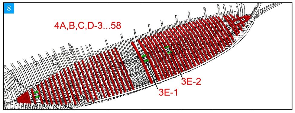
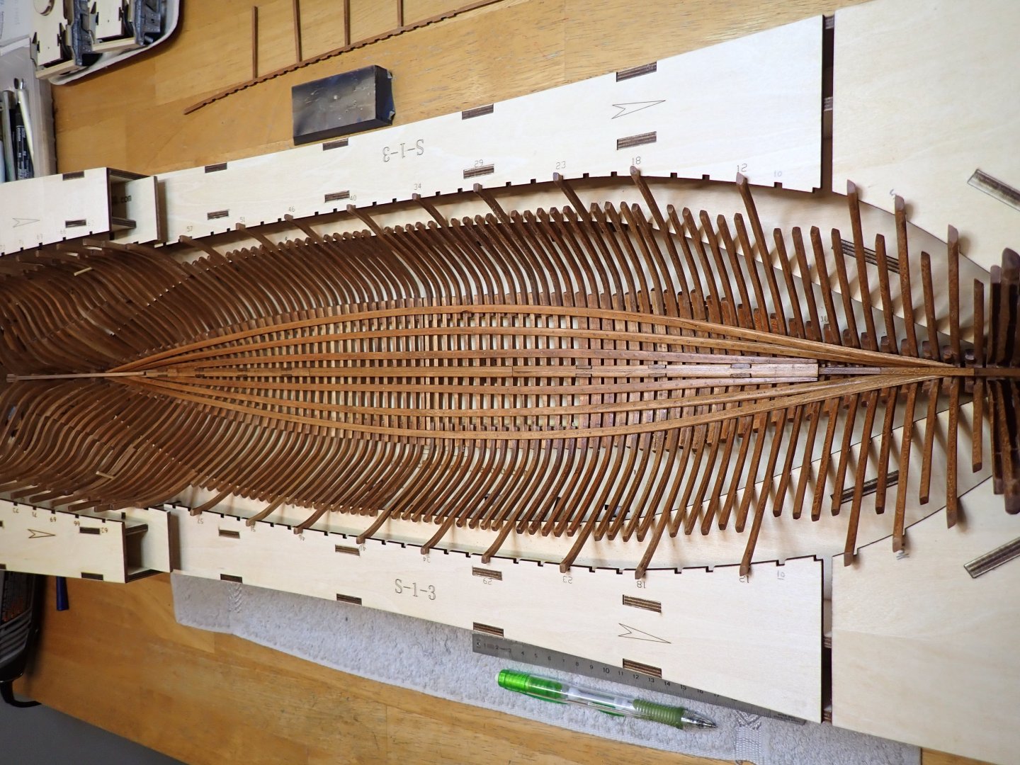
I was planning to finish the stern (and the Session #1 by the same token), but it is not possible (or practical) because of the cradle. At this stage, I have no other choice than starting the installation of the deck beams. I know it is hard, but someone has to do it... 🙂 I decided to install the central beams as they are the pivot of the whole deck and it will allow me to position correctly the mast base. Lots of beams to install (about 58) plus the platforms for the bow and stern. That should be interesting. Once this is done, it may be possible to extract the assembly out of the cradle. We will see. Yves
- 185 replies
-
- 18
-
-
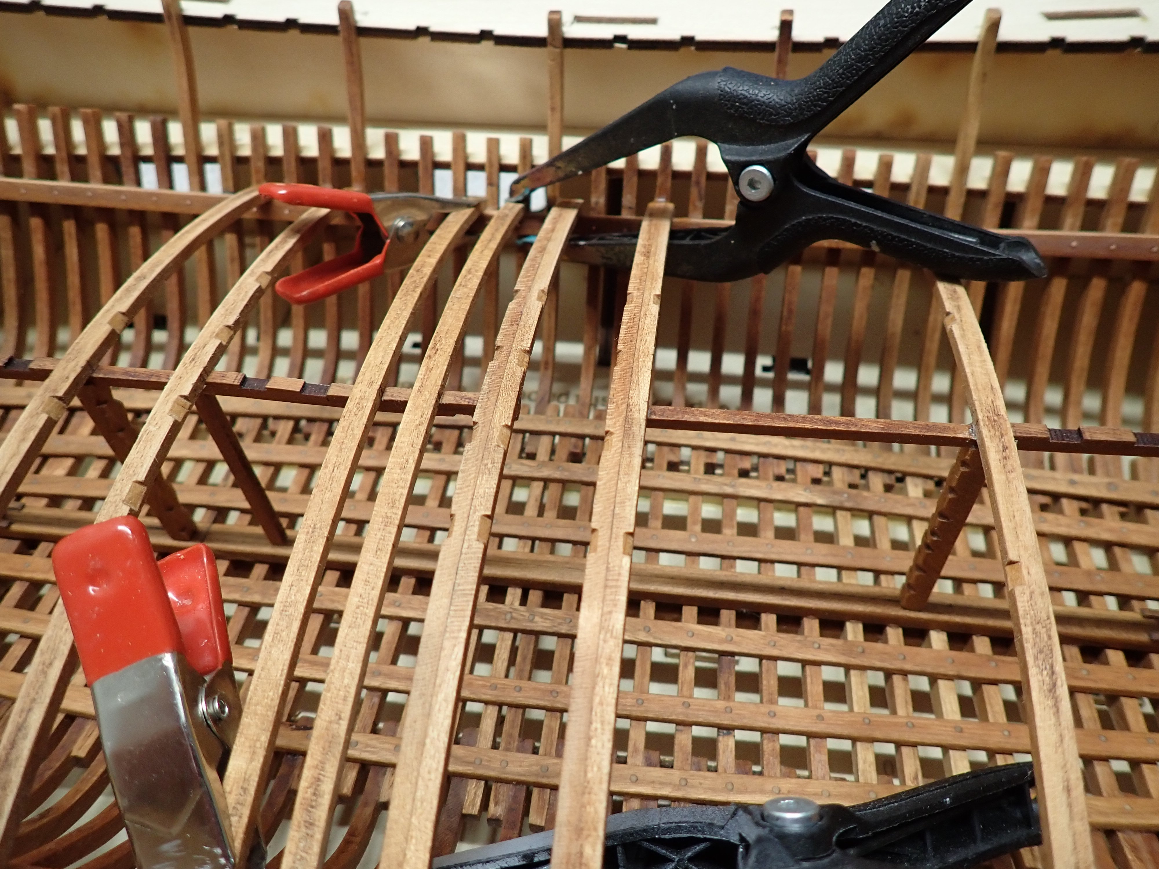
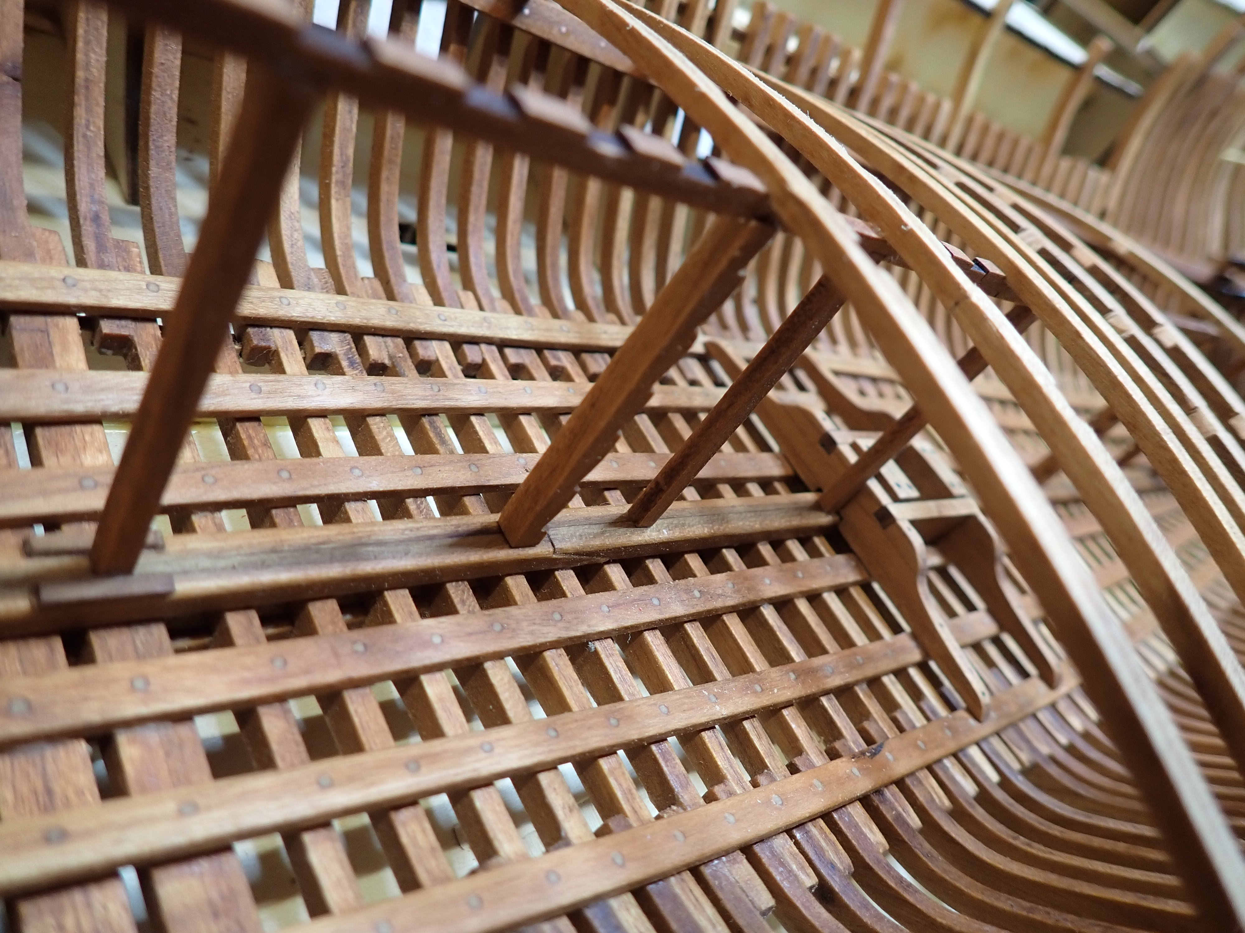
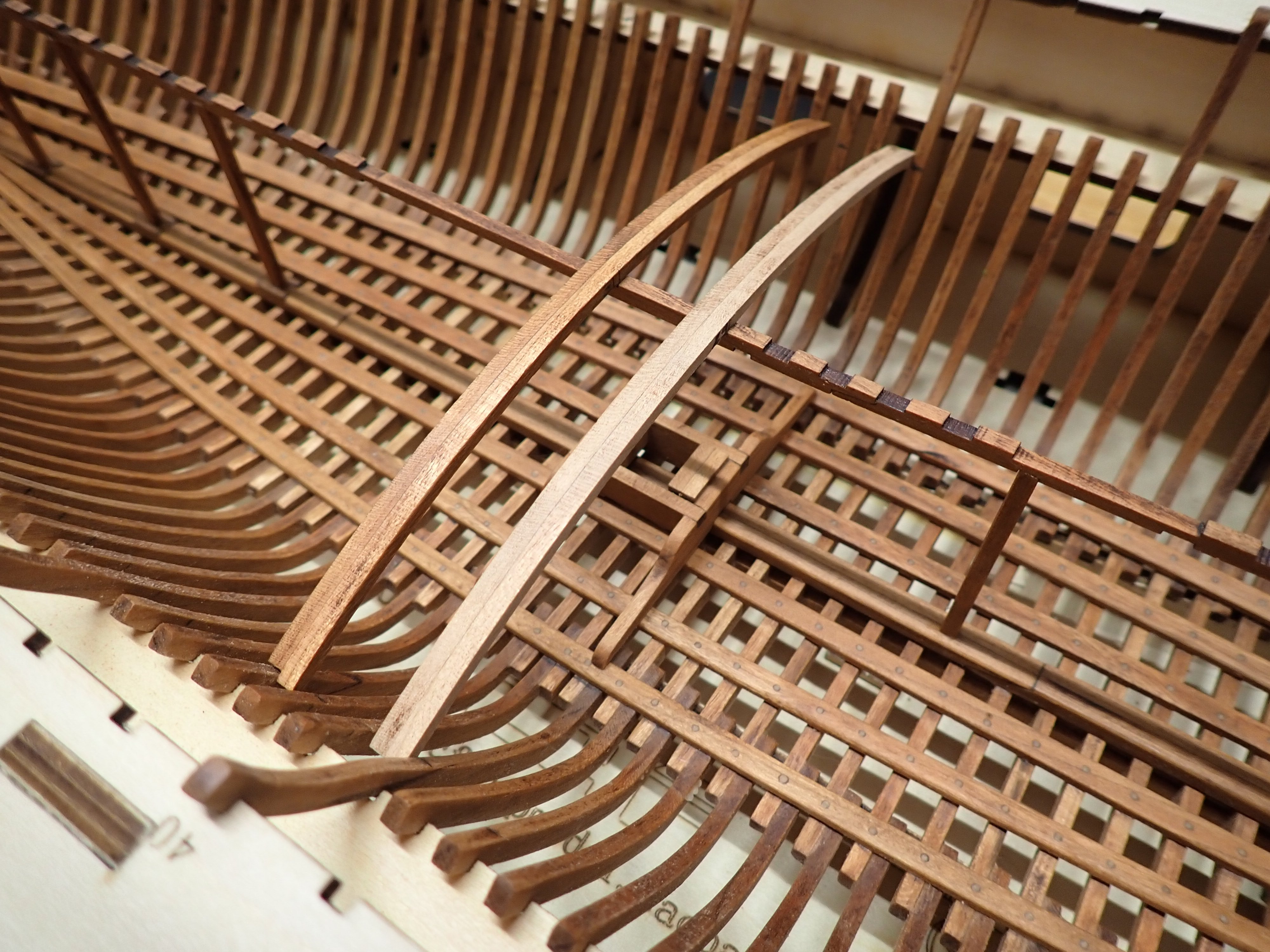
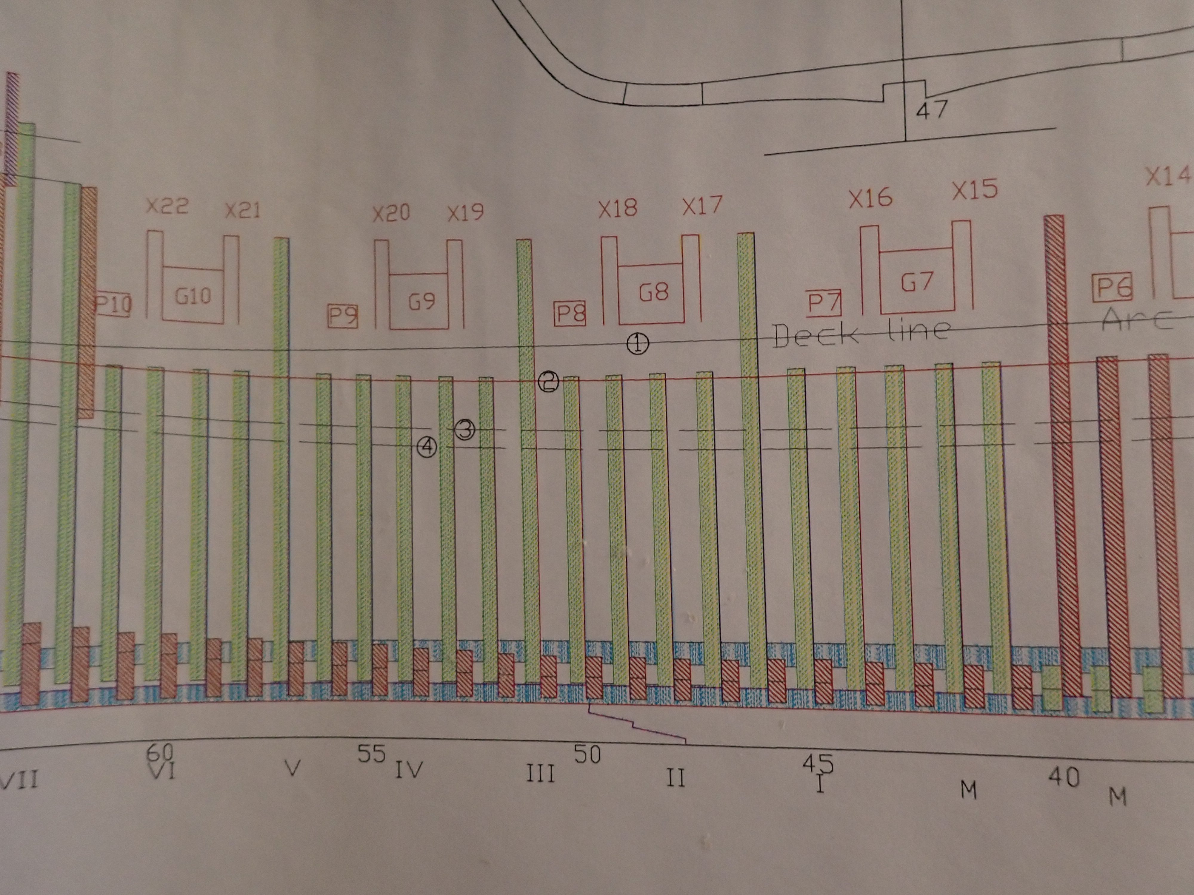
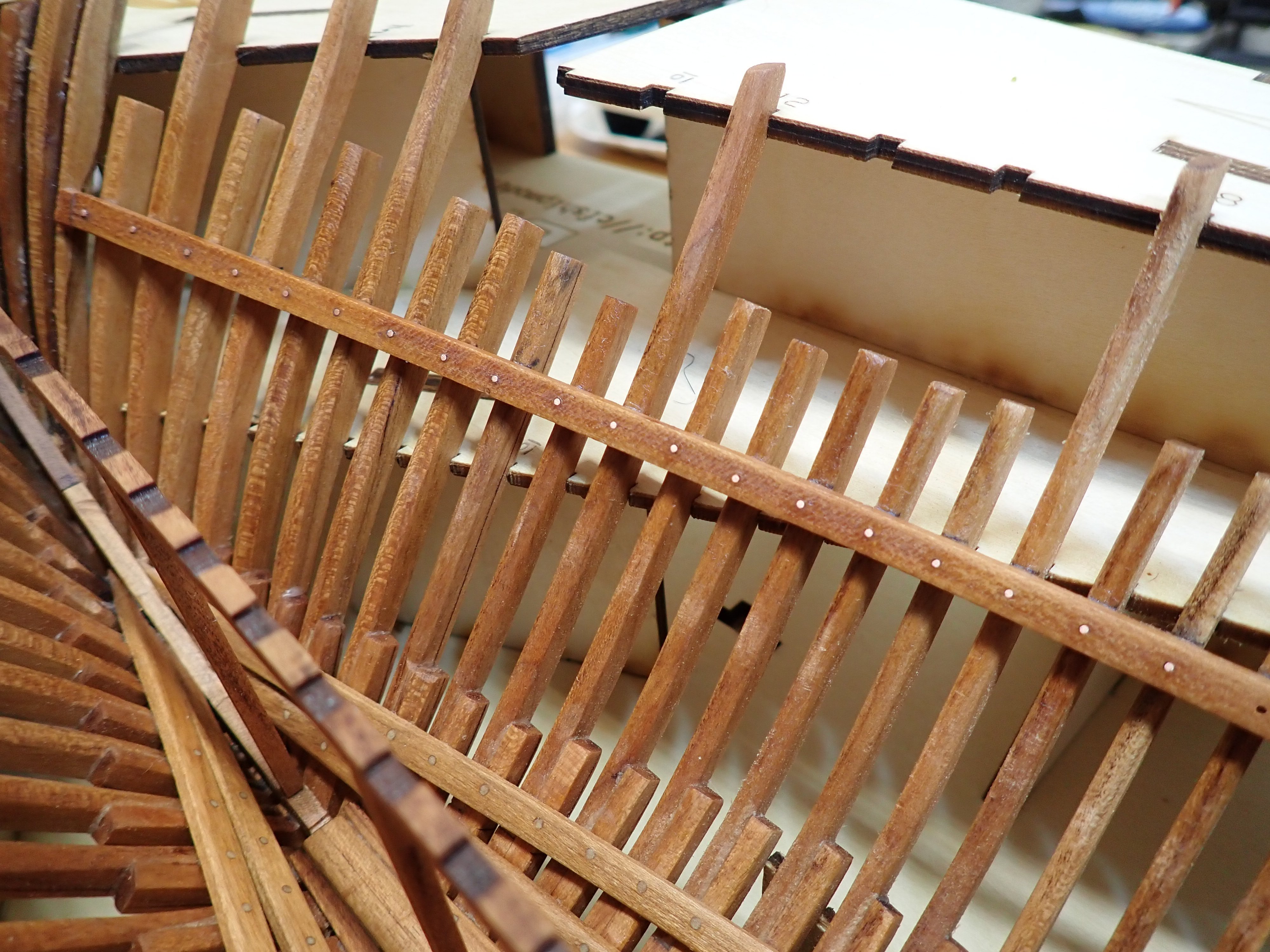
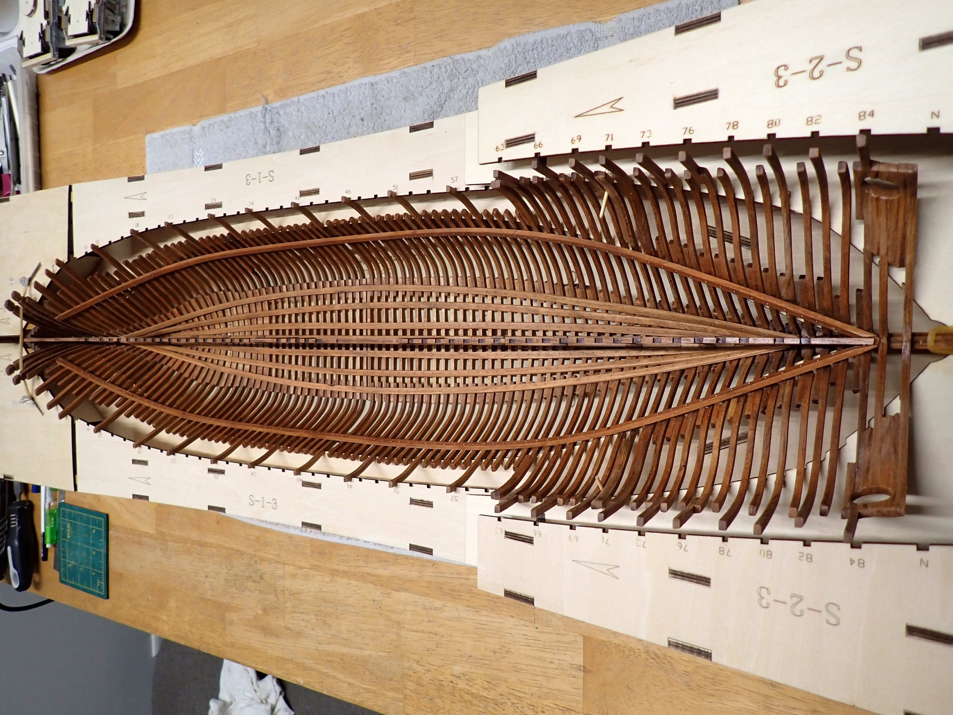
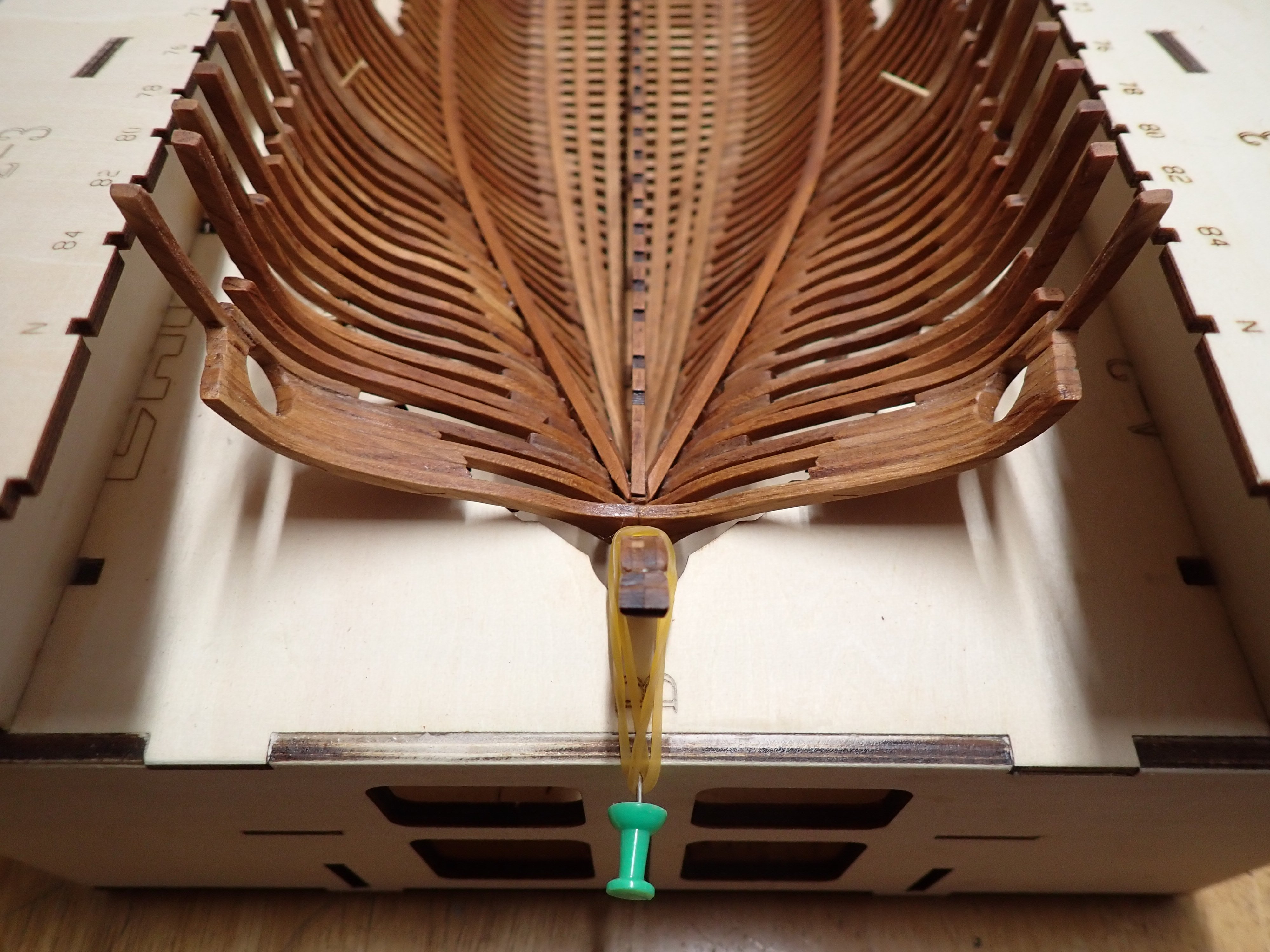
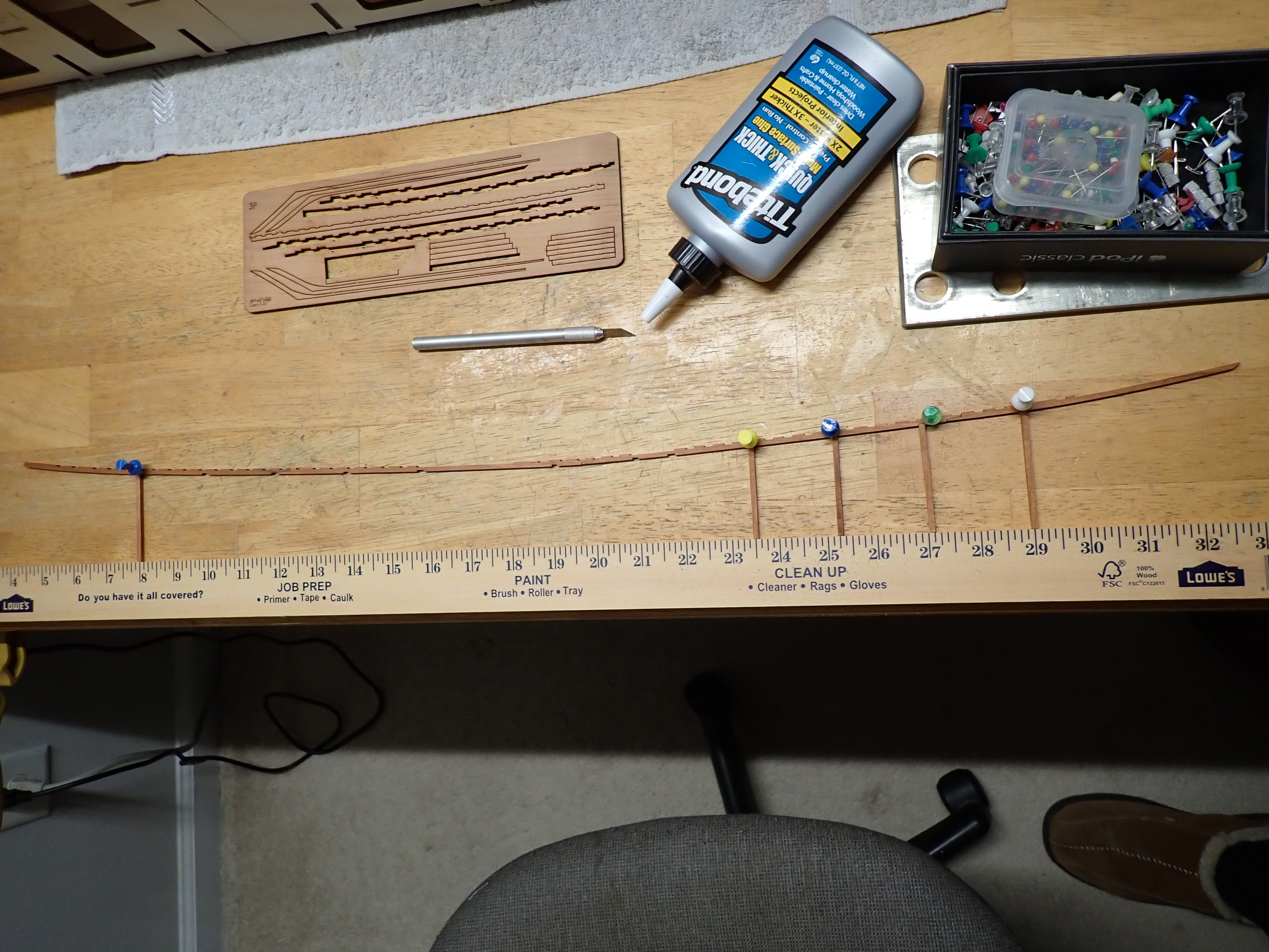
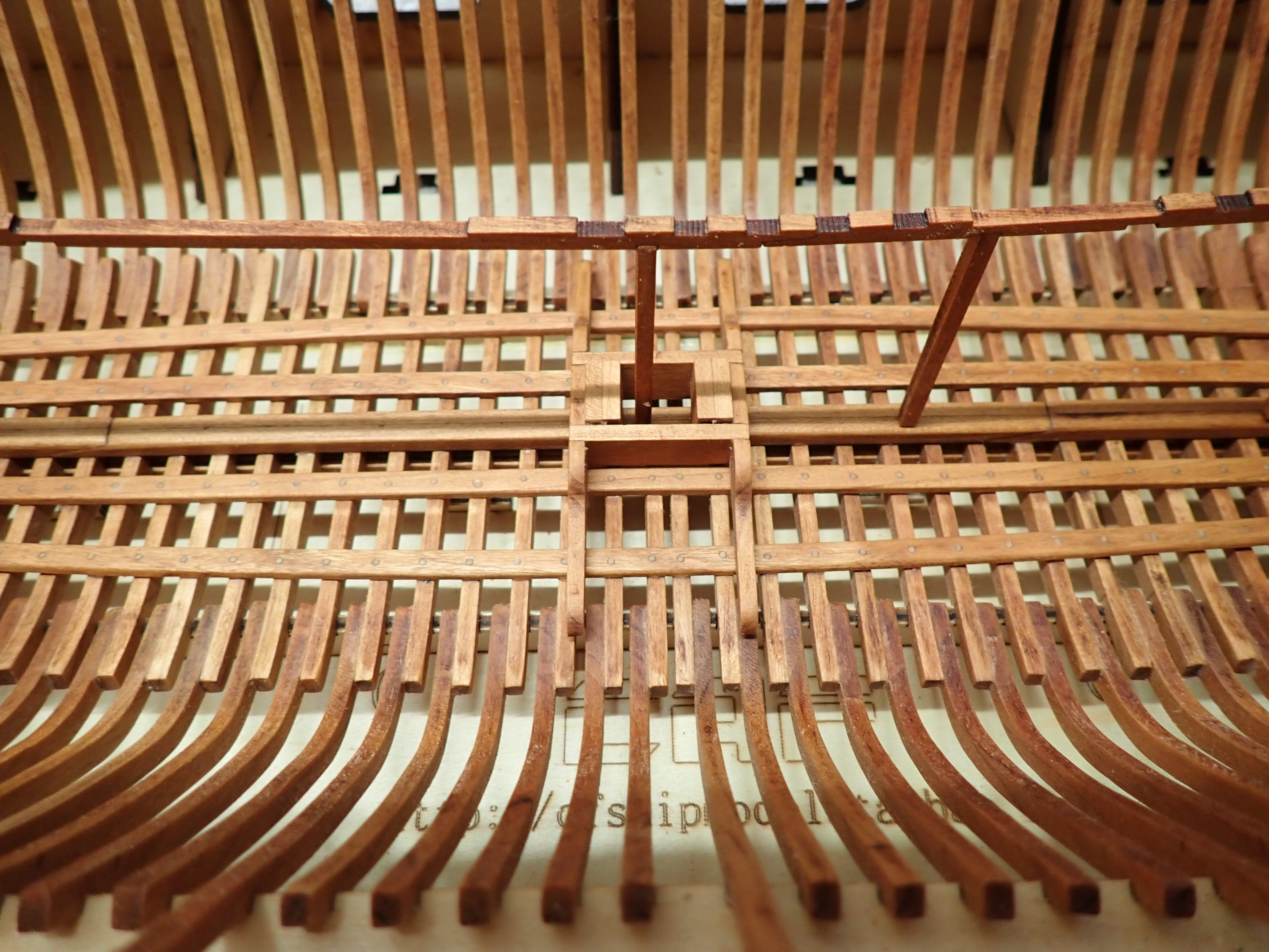
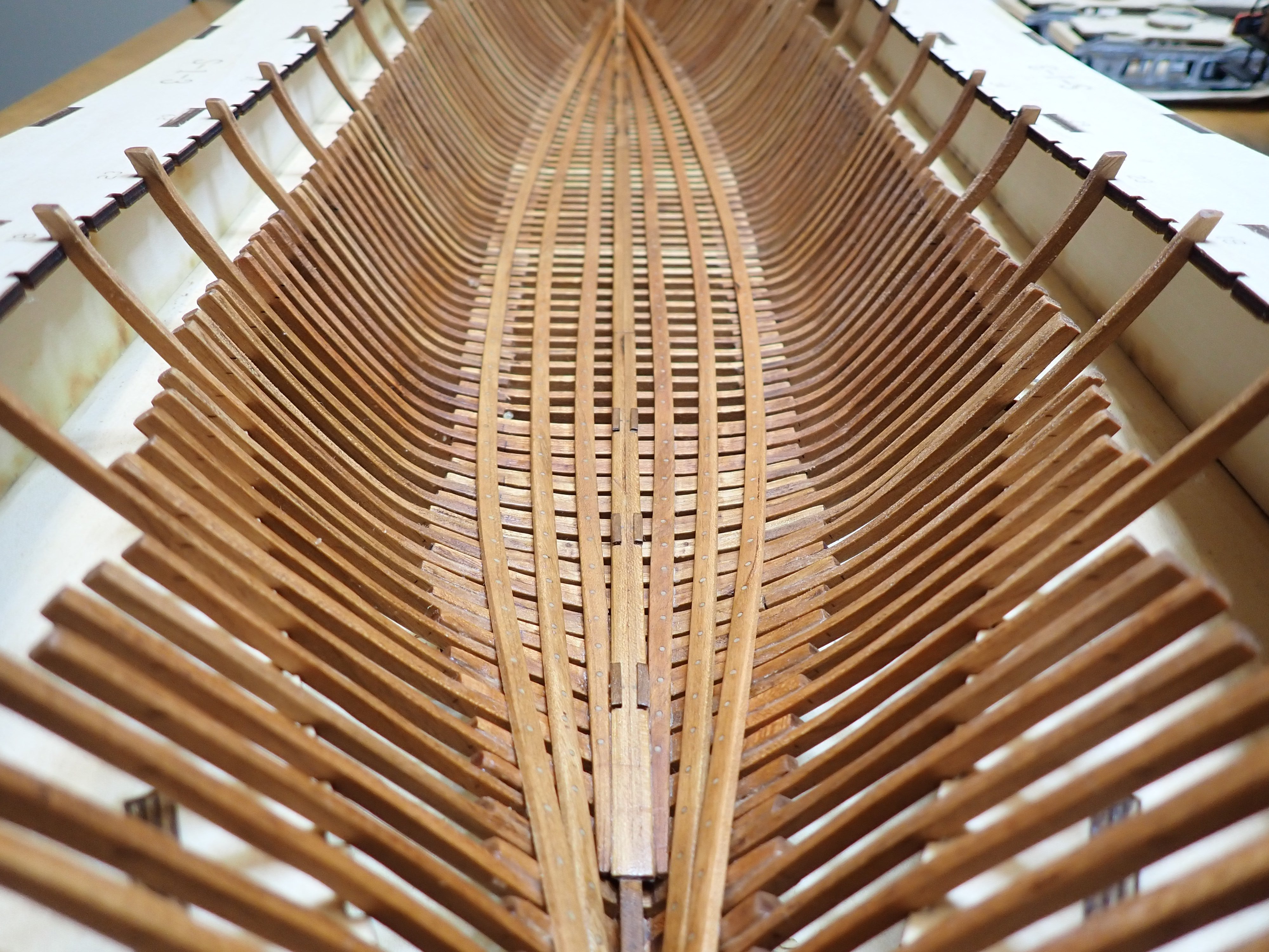
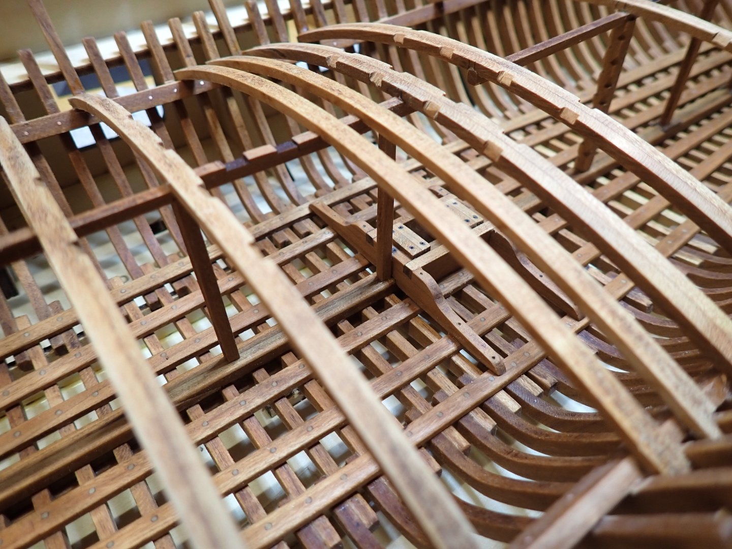
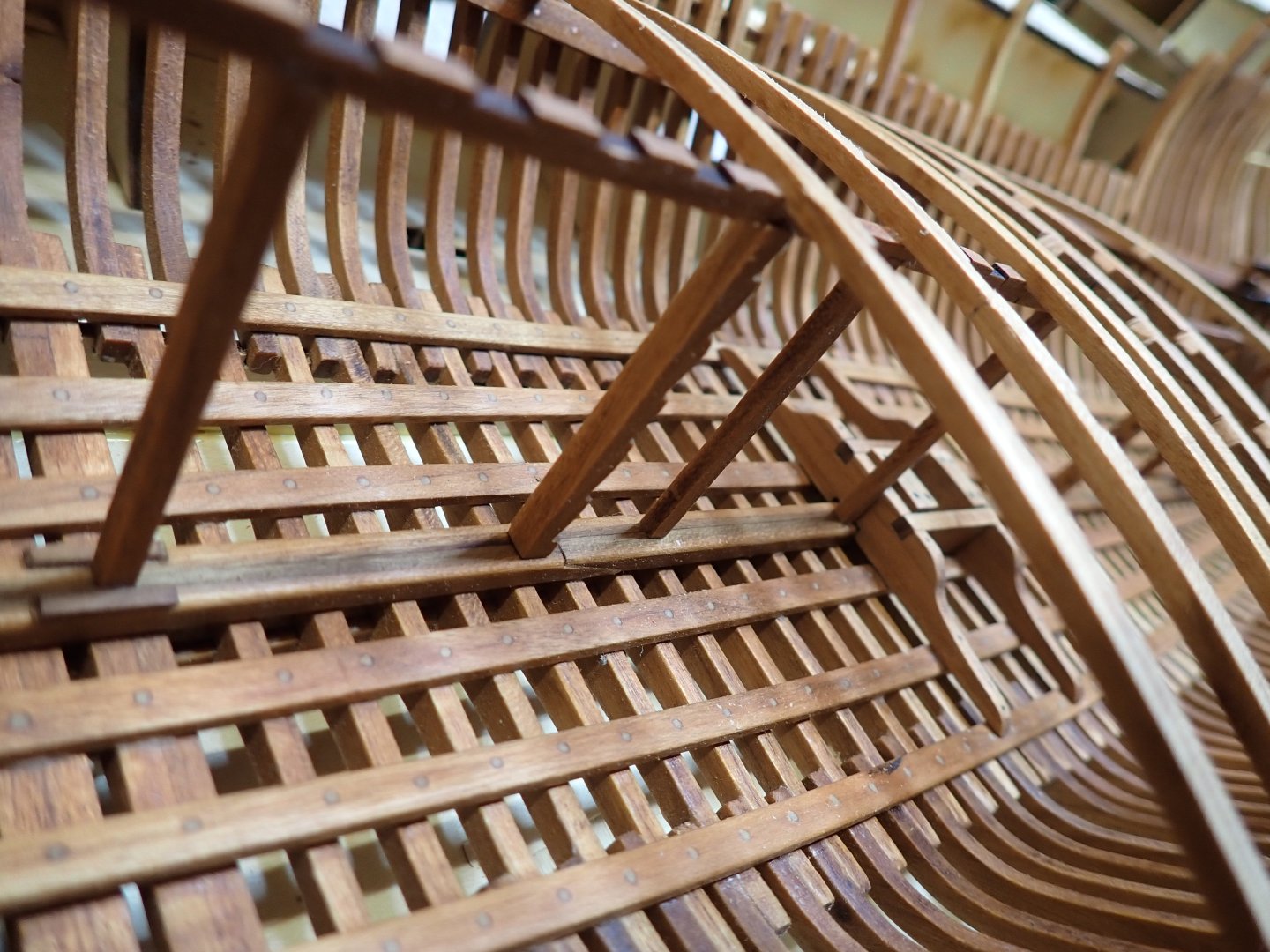
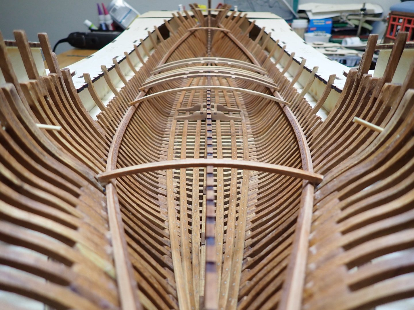
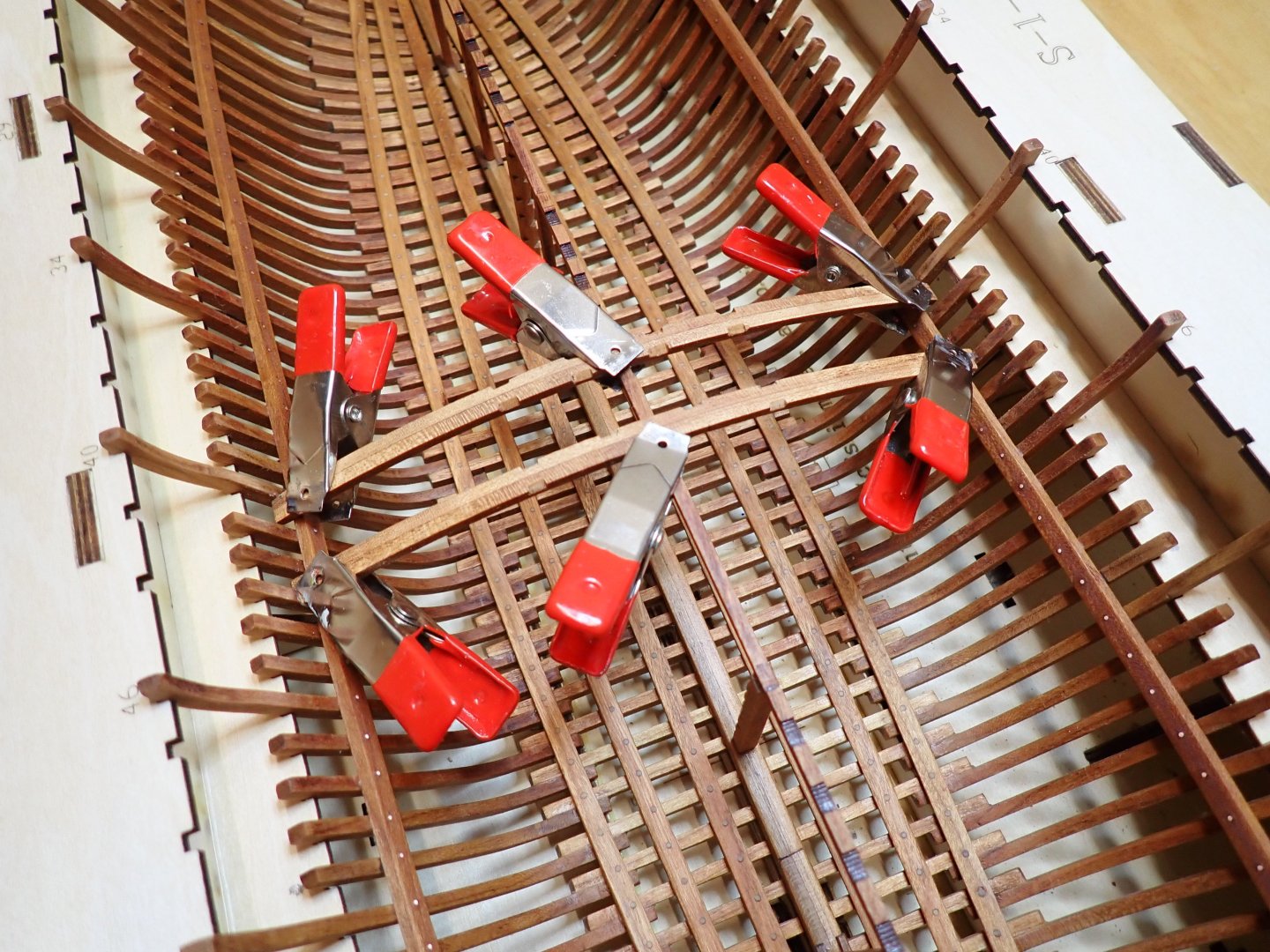
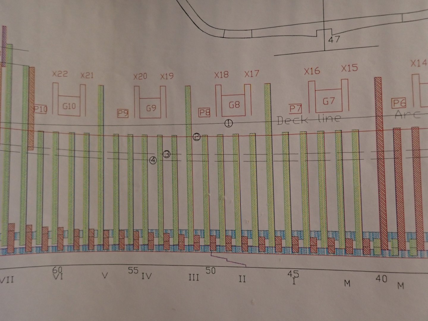
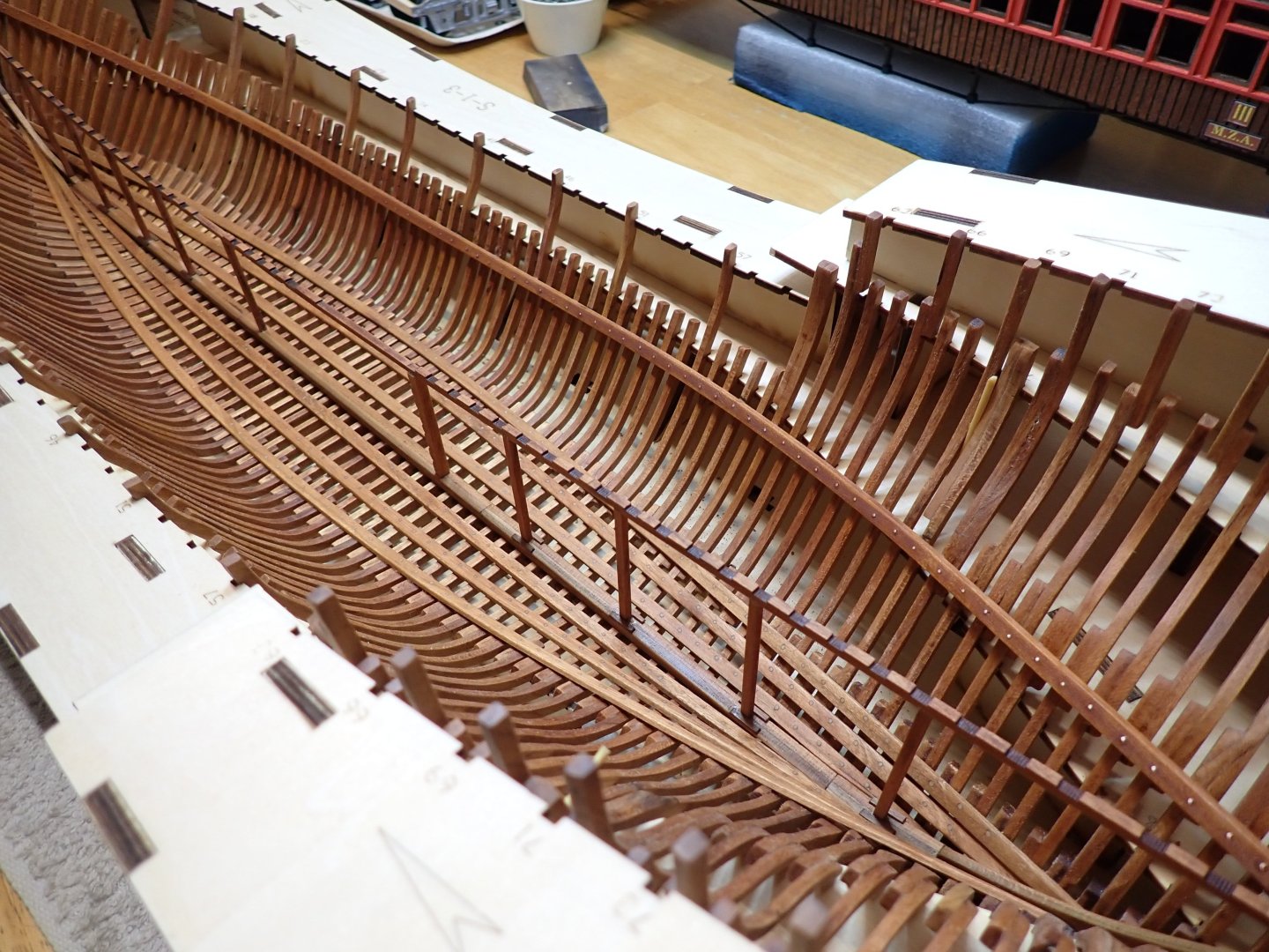
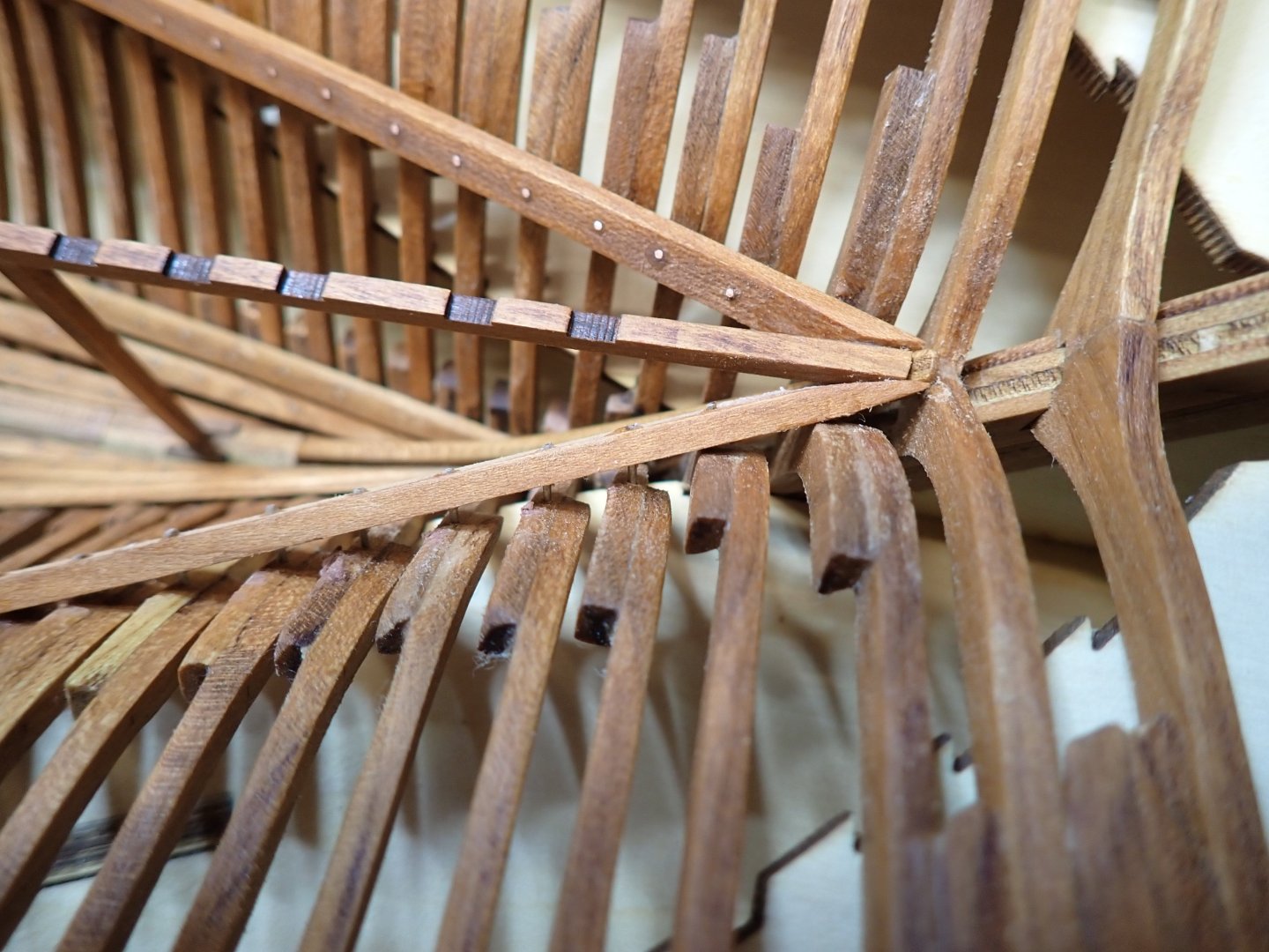
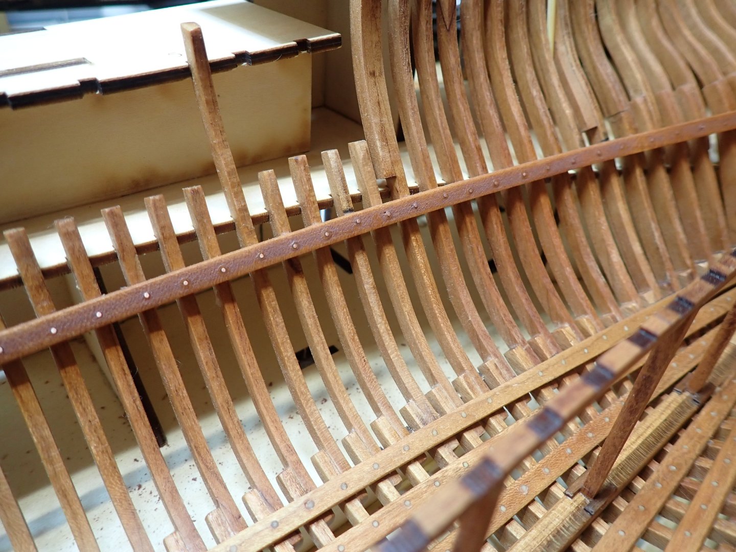
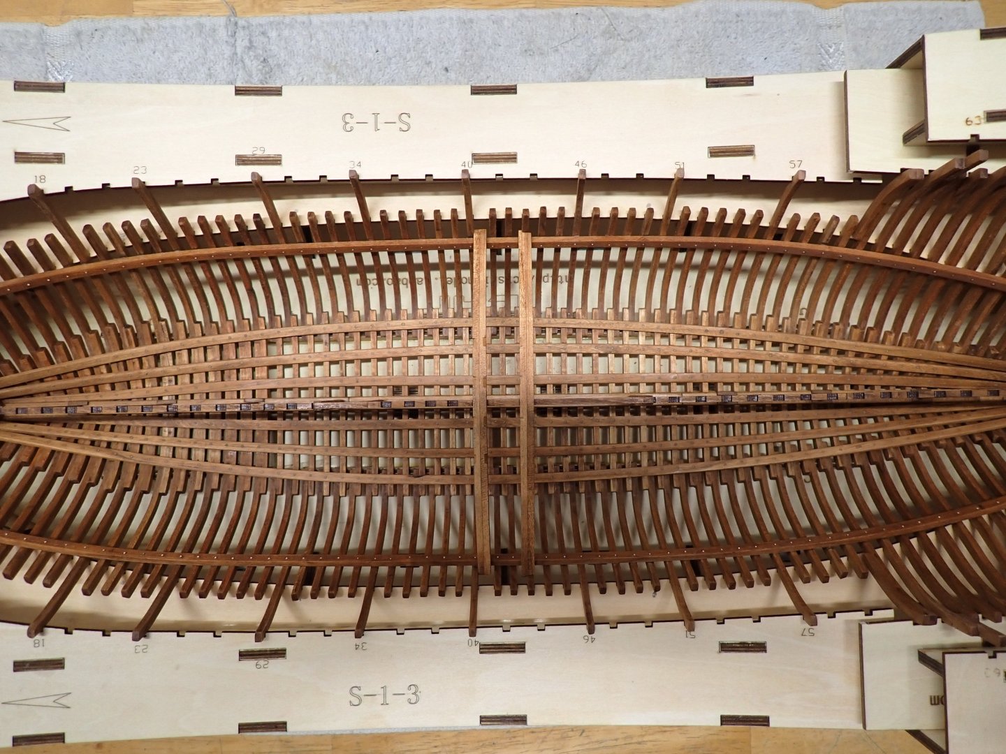
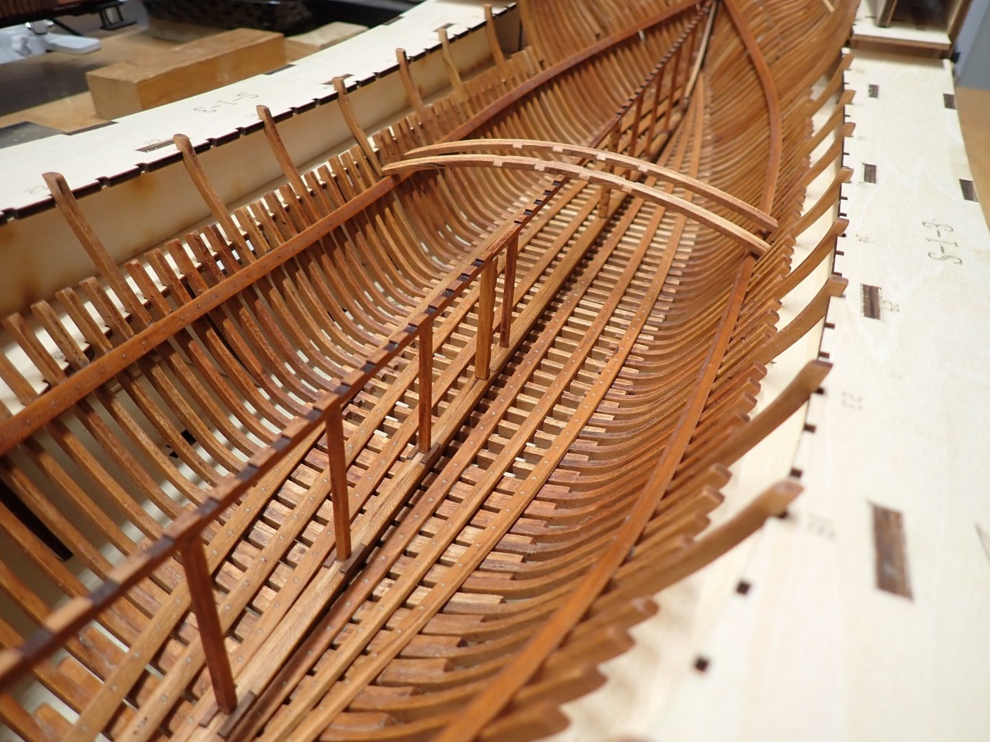
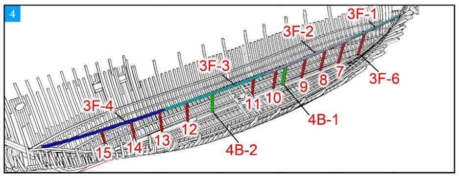
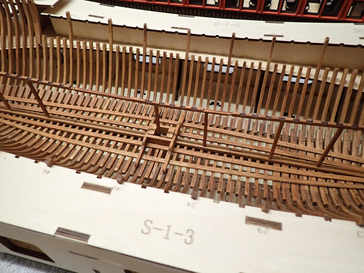
A quick update and a major milestone completed for me: the building of the deck frames supports in the hull. The central support has been installed: To position correctly the 3x5mm deck frames support on each side of the hull, I am approaching it in two ways: 1) An approximate marking using multiple deck frames. It gives me some kind of indications. 2) Using the plan, a precise measurement from the base of the cradle: It is the line marked "4". I am using a measure every ten frames. When happy, it is time to glue, using CA glue and strong fingers pressure, since there is no easy way to position these 3 x 5 supports. Once glued, I am drilling through the beam and into each frame. A real nail (pin of electronic components - 0.8 mm diameter) is inserted after coating the "nail" with CA glue. Then some sanding, oiling and waxing. The nails are useful in places where the frames are not touching very well the beam, due to the poor fairing of the internal hull. This is mostly the case in the stern (see above). Both sides are now done...sighs. I hope it will be alright. There is no coming back. Next, I am going back to the Session #1 and will try to finish the stern: Overall, I am very happy to have this milestone behind me. It was not the most pleasant thing to do. Yves


- 185 replies
-
- 20
-
-
You are doing a good job with the planking. It is going to look great. Yves
-
Kevin, I hope you will be gifting us with a separate Build Log. That should be monumental !!! Yves
-
Superbe. Yves
-
Great progress. You are ready for planking. Yves
-
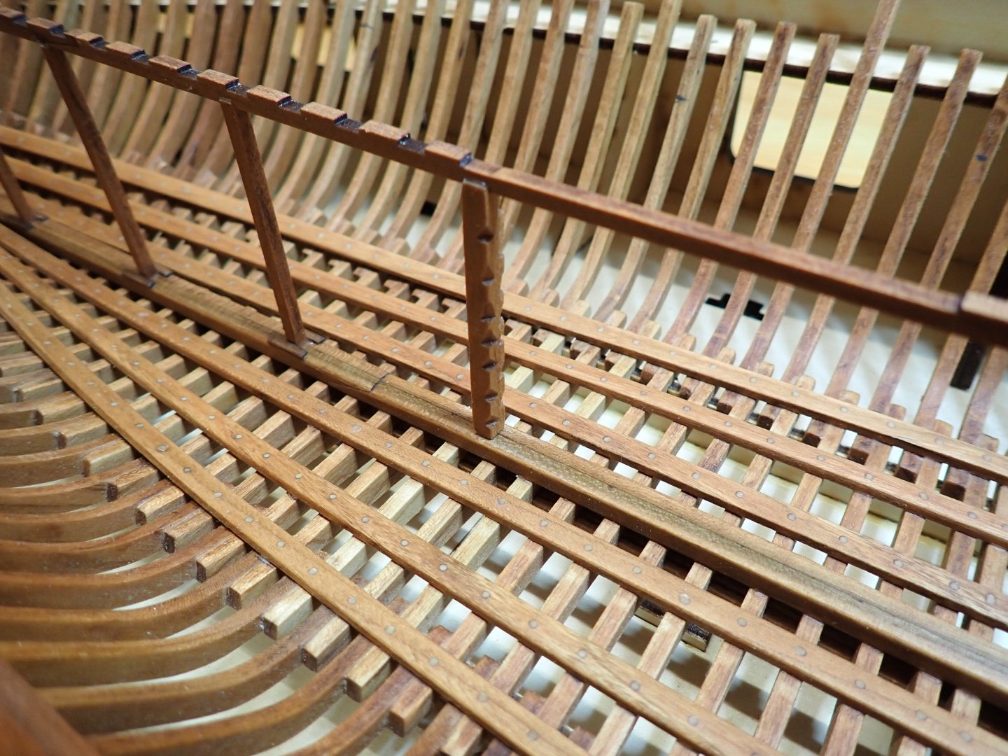
While working and measuring multiple times for the installation of the deck frames supports (3x5 mm), I have built the ladders used by the crew to reach the lower level: These parts are funny to build, with a small triangular file. The crew must have been very agile to use this kind of ladder, that literally requires your two hands and two feet to get to the upper deck. Yves
- 185 replies
-
- 18
-
-
Your efforts remind me of what some modelers have done for the Trumpeter Titanic hull. It is massive but should pay off, in the end. Yves
-
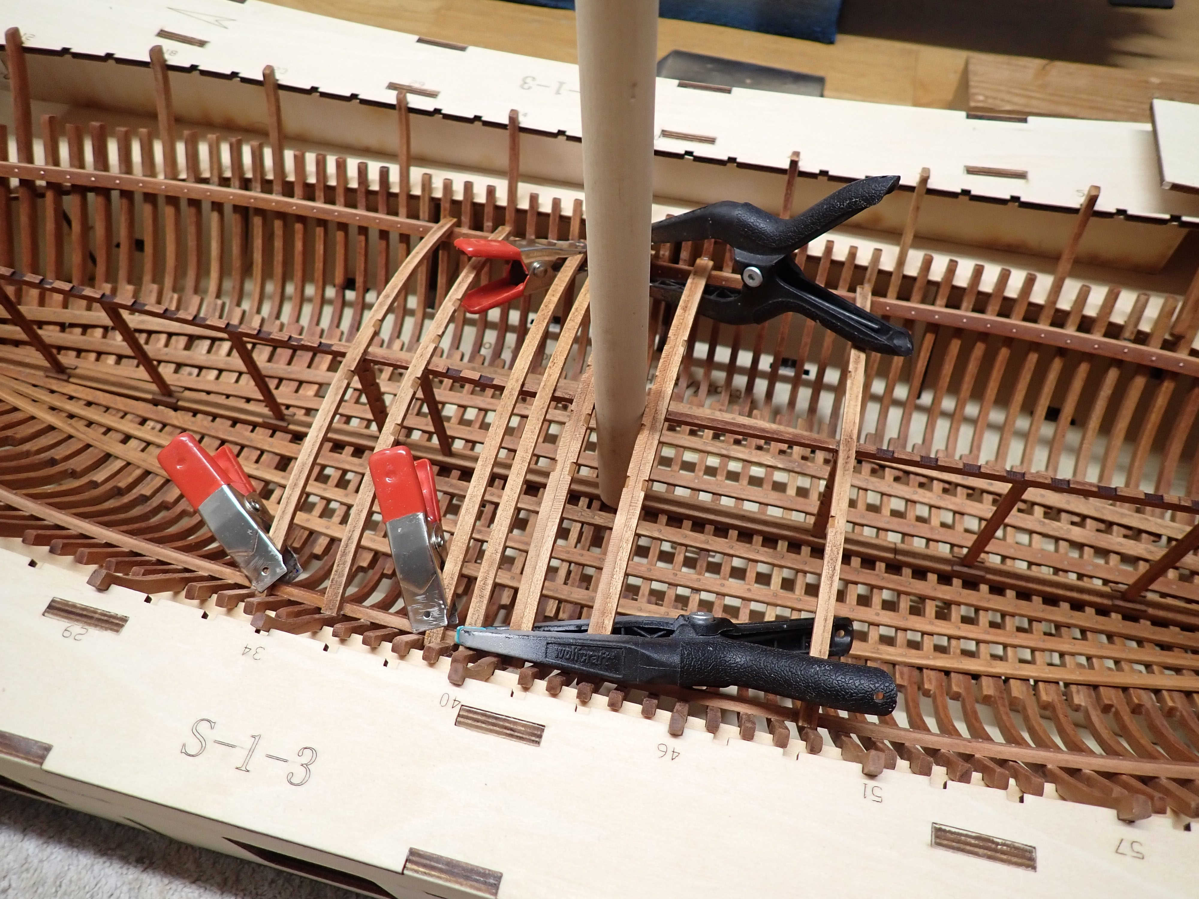
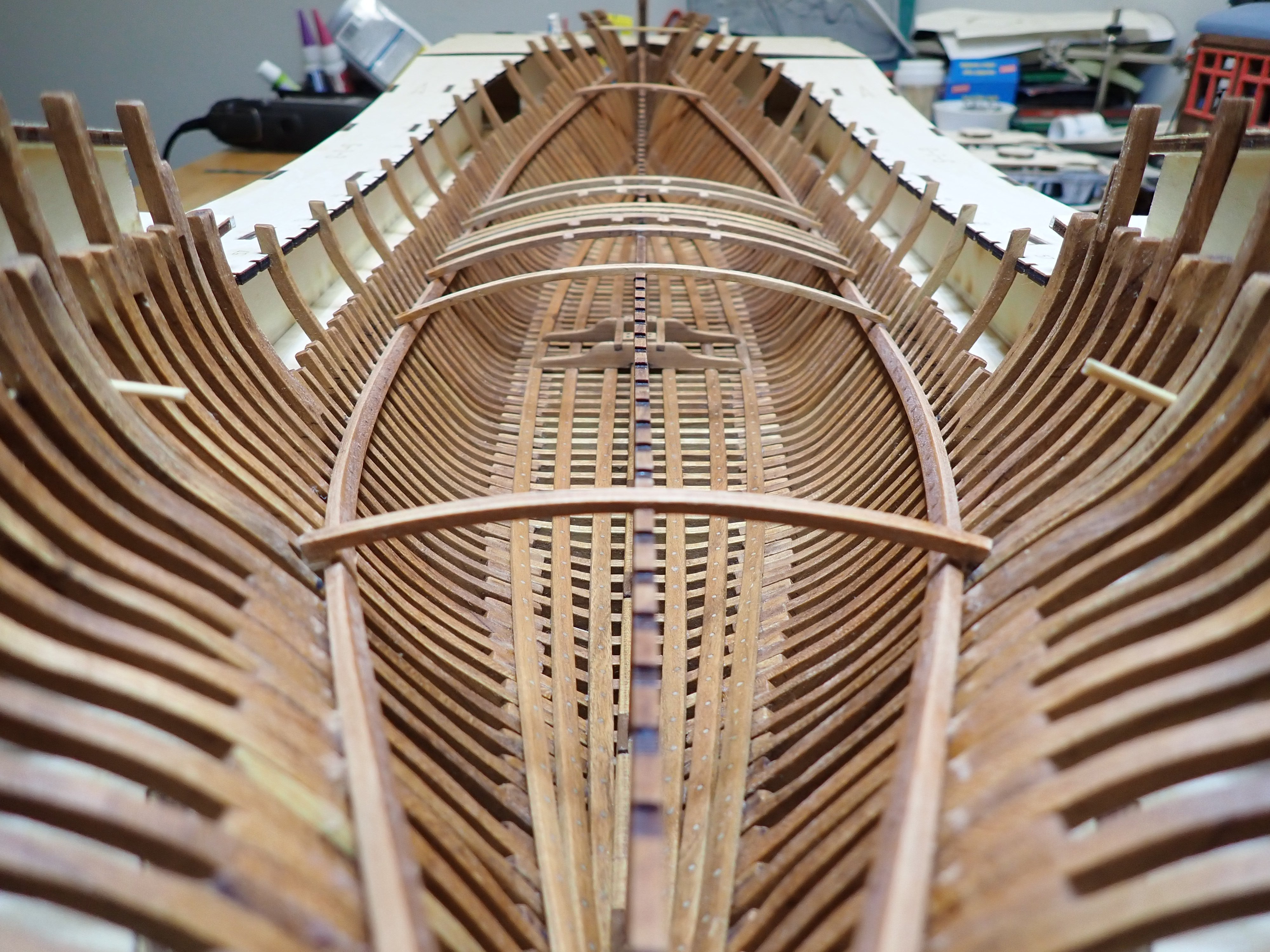
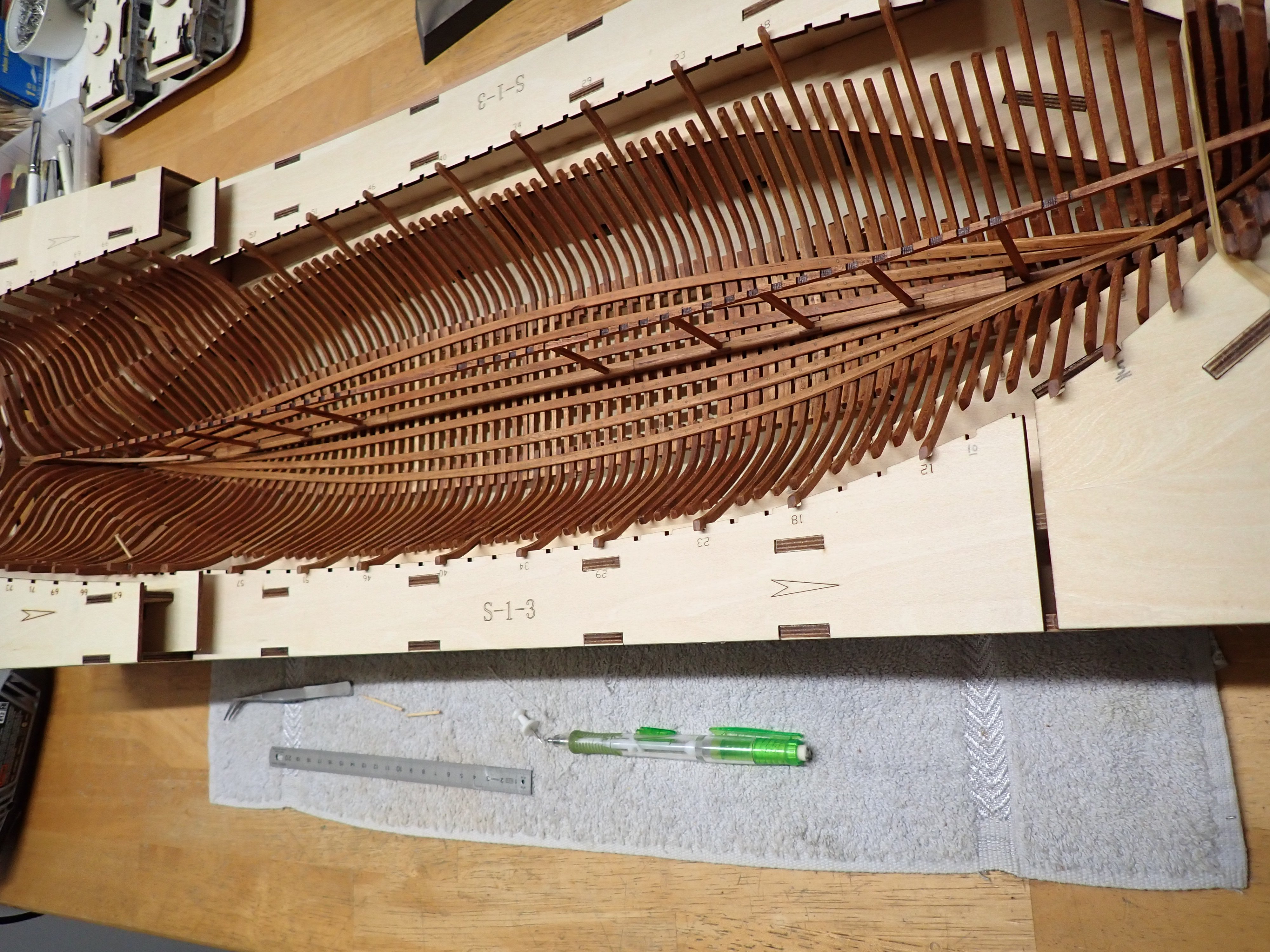
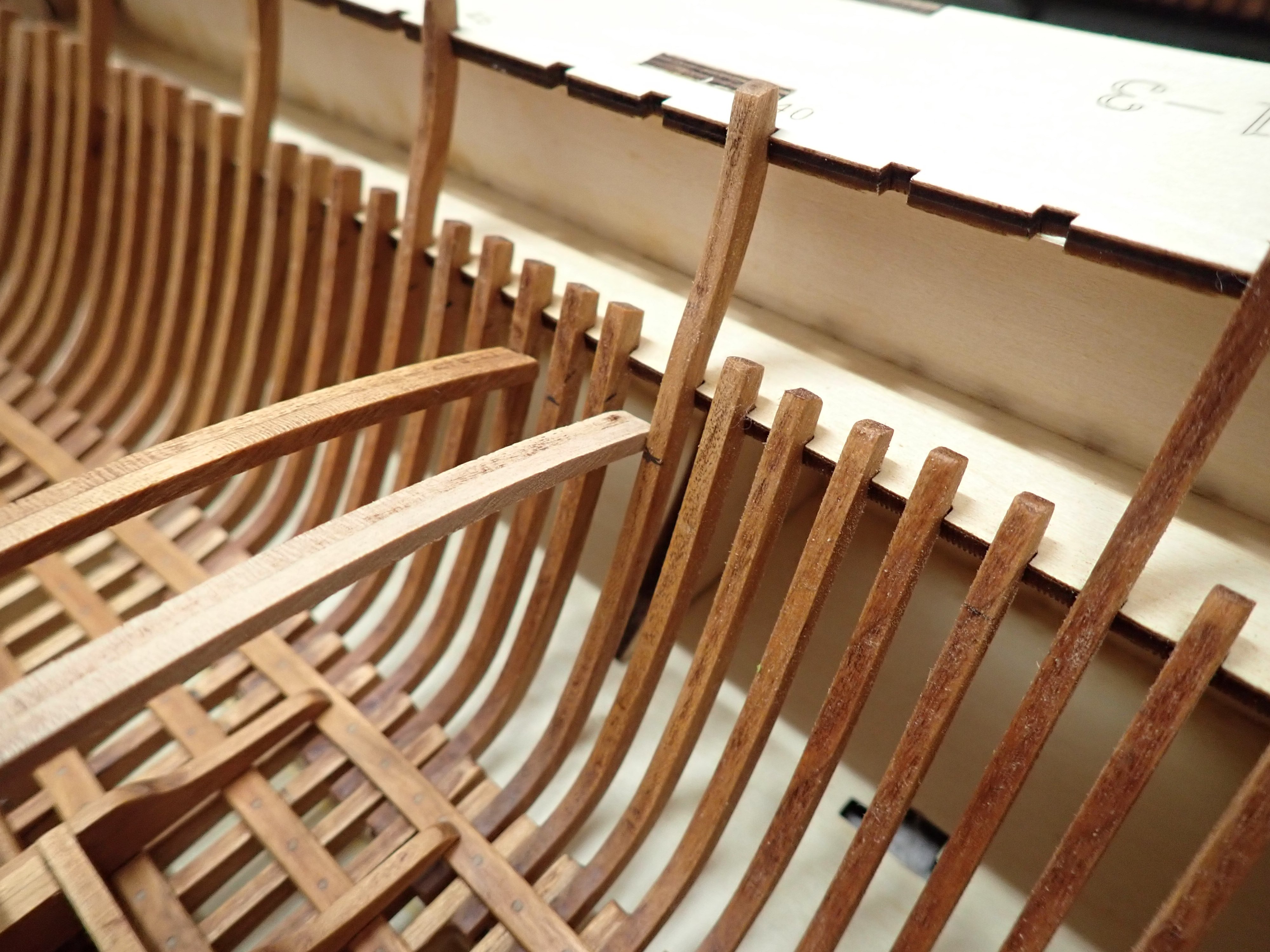
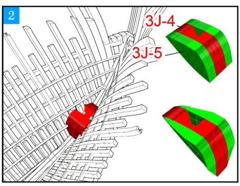
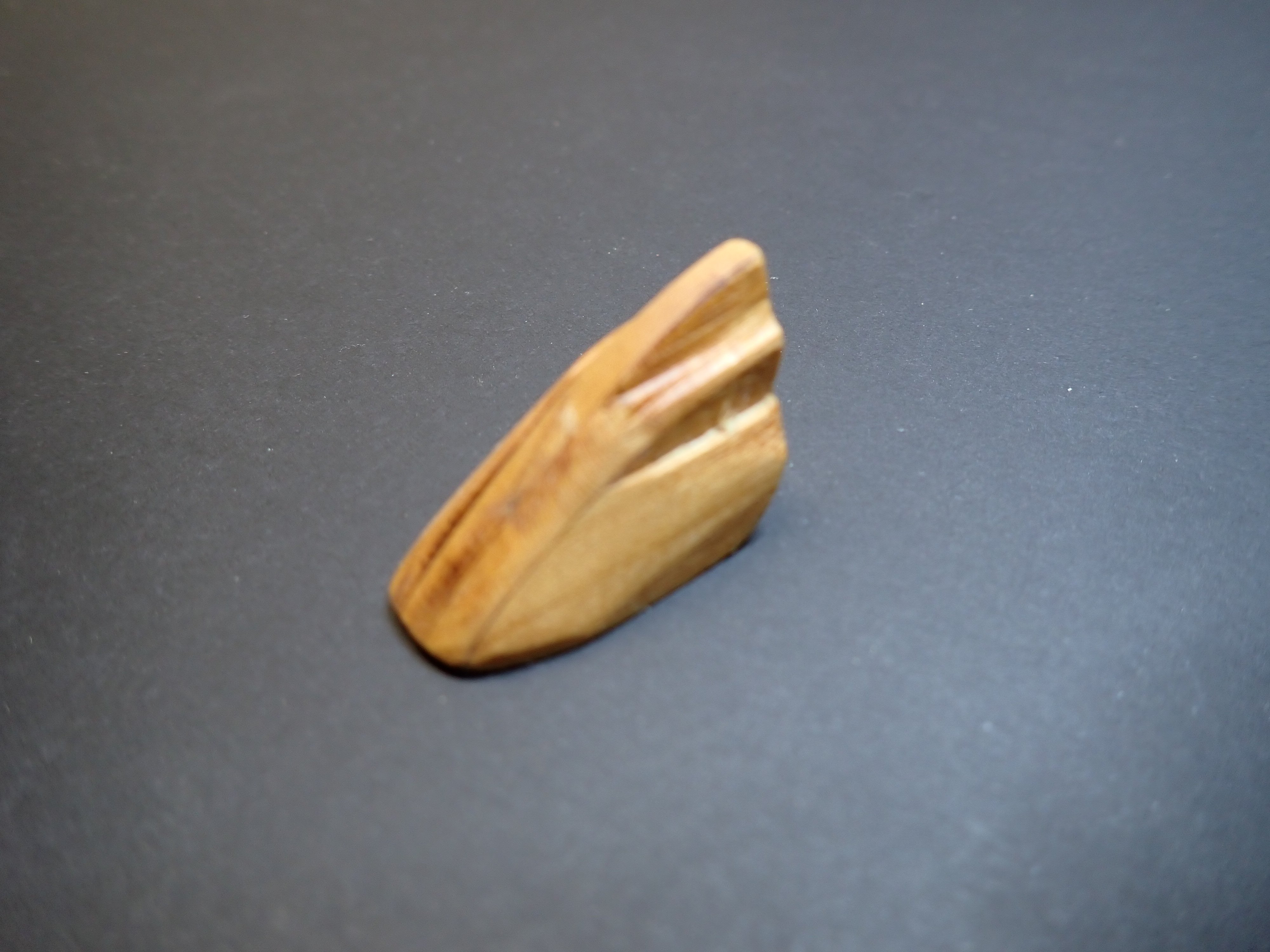
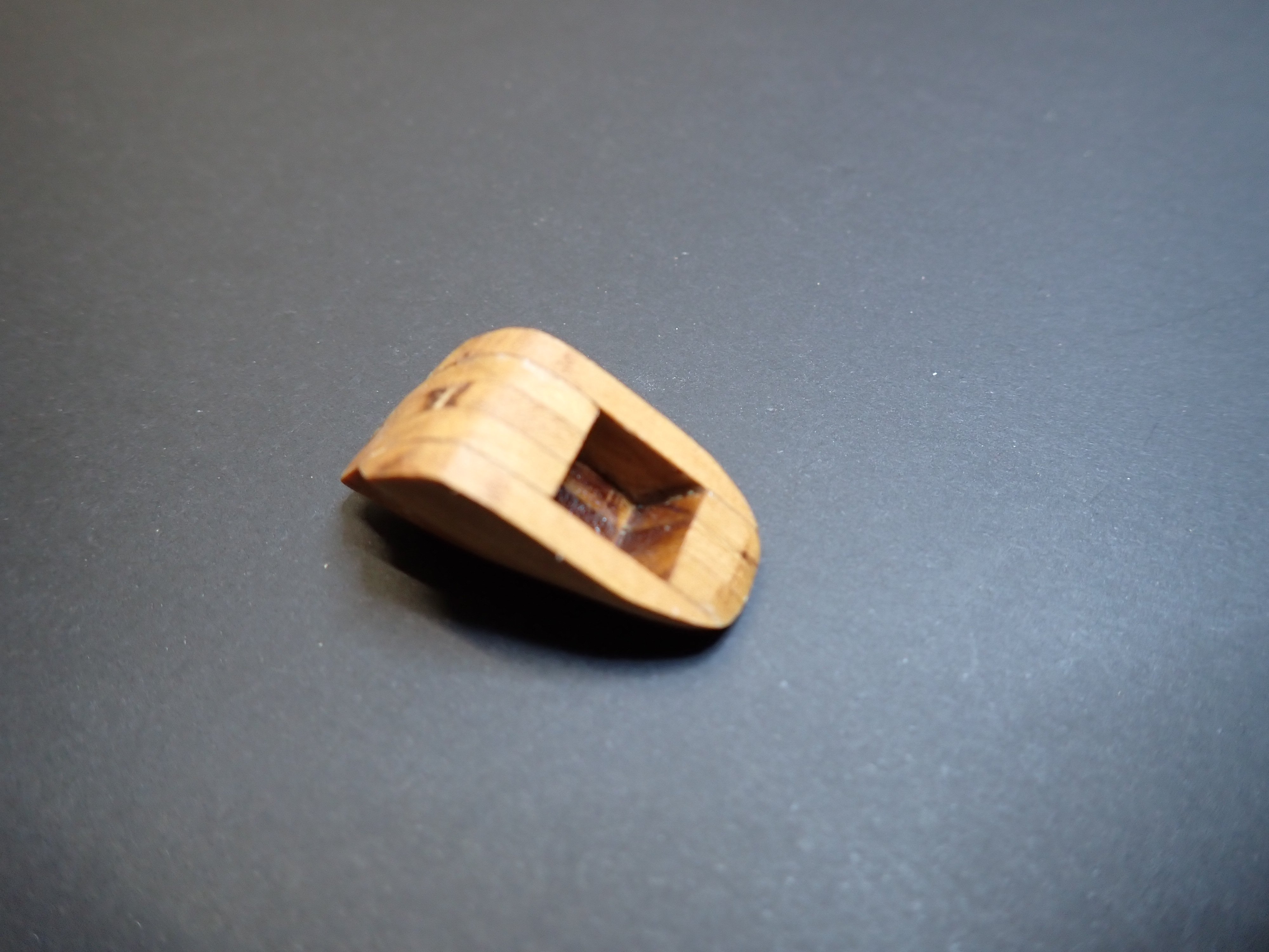
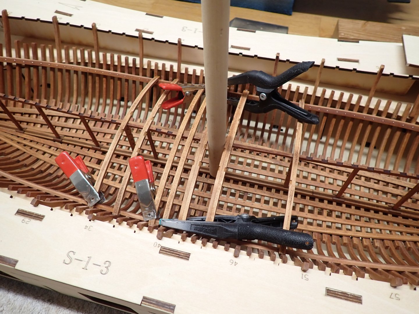
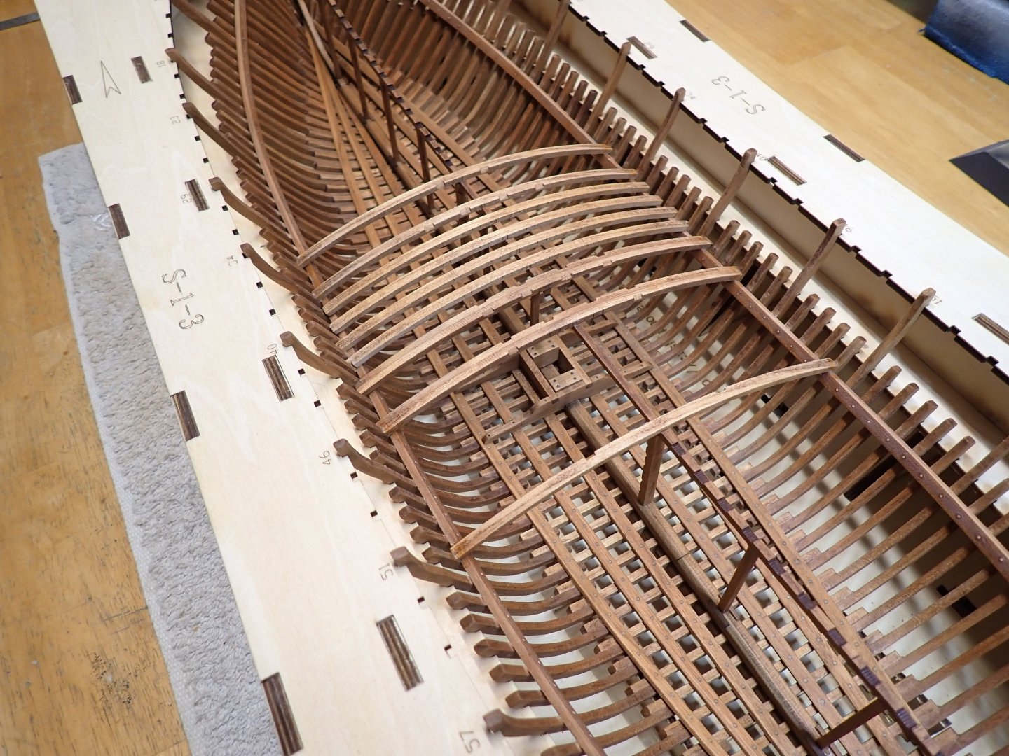
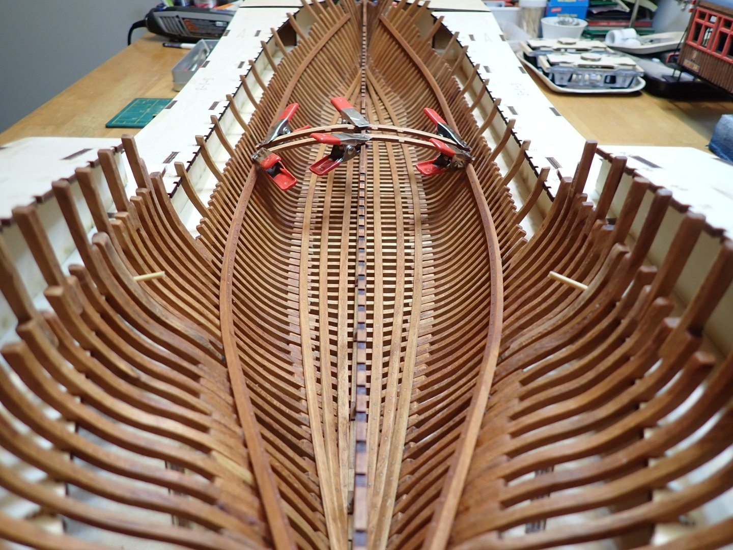
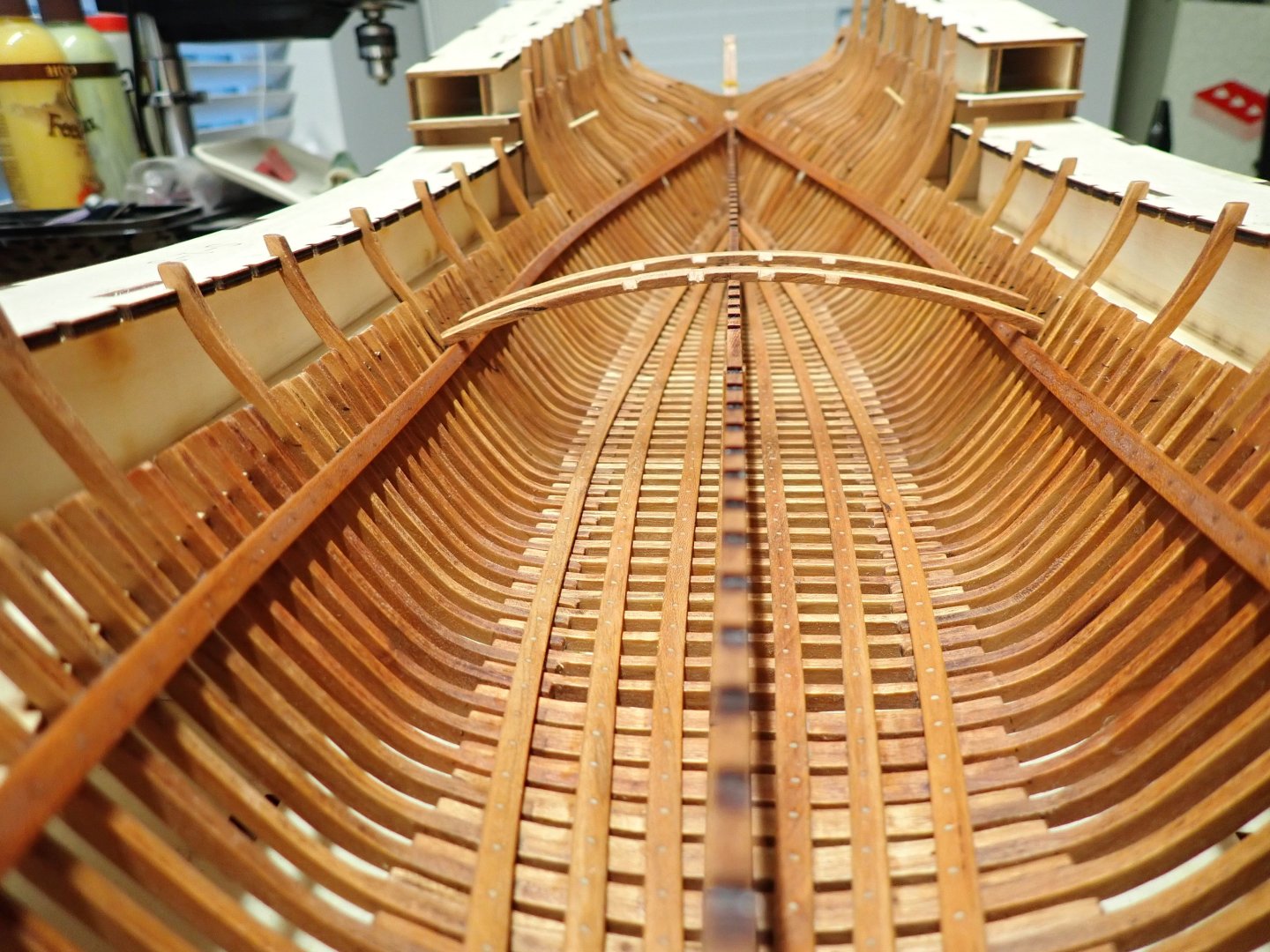
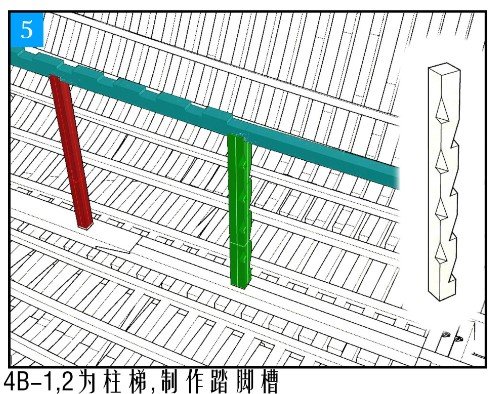
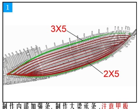
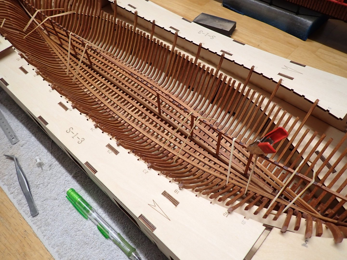
As indicated by the picture below (Session #2), I have installed three sets of the 2x5 planks. I am stopping there. Now, the dreaded prospect of gluing the 3x5 mm planks is coming. There are really no clear indication on how to do that, besides a little tick mark on the frames, that comes somewhat in the middle of the deck beams. It is really not precise at all. In addition, securing the deck beams supports (3x5mm - Green) is not an easy task, because of the lack of access due to the constraining cradle. Instead, I decided to move on and install the deck beams central support as well as possible, making sure that it lines up with the deck beams and from there, determine where the 3x5mm supports have to be installed. It is going to be tedious but that is the only way I see it possible. Once this assembly is in place, I hope by positioning a few deck beams, to be able to trace the exact position of the 3x5 supports, on the frames. That central assembly (3F-1 to 3F-15) is super fragile and requires a lot of care. It is first assembled flat on a bench: Then, many dry-runs are made to position it in the best possible way. One of the vertical holders is ending right in the middle of the mast base, which is not good. I will adjust this later. The mast base is not glued yet and will be glued later, when some of the major deck beams have been installed. There is a lot of conflicting information between the Monograph, one of the CAF plans and the other CAF plan (!) Not easy to figure out exactly where the main mast should sit. Finally, the central support is installed and the CA is drying.... Wish me luck.... I really have no idea if that is going to work. Yves

- 185 replies
-
- 18
-
-

-
Well, these kits are expensive but support is top. It reminds me a little bit of what CAF Model does on the wooden ships side. Yves
-
That is really nice. I love the little origami they included with the note. Yves
-
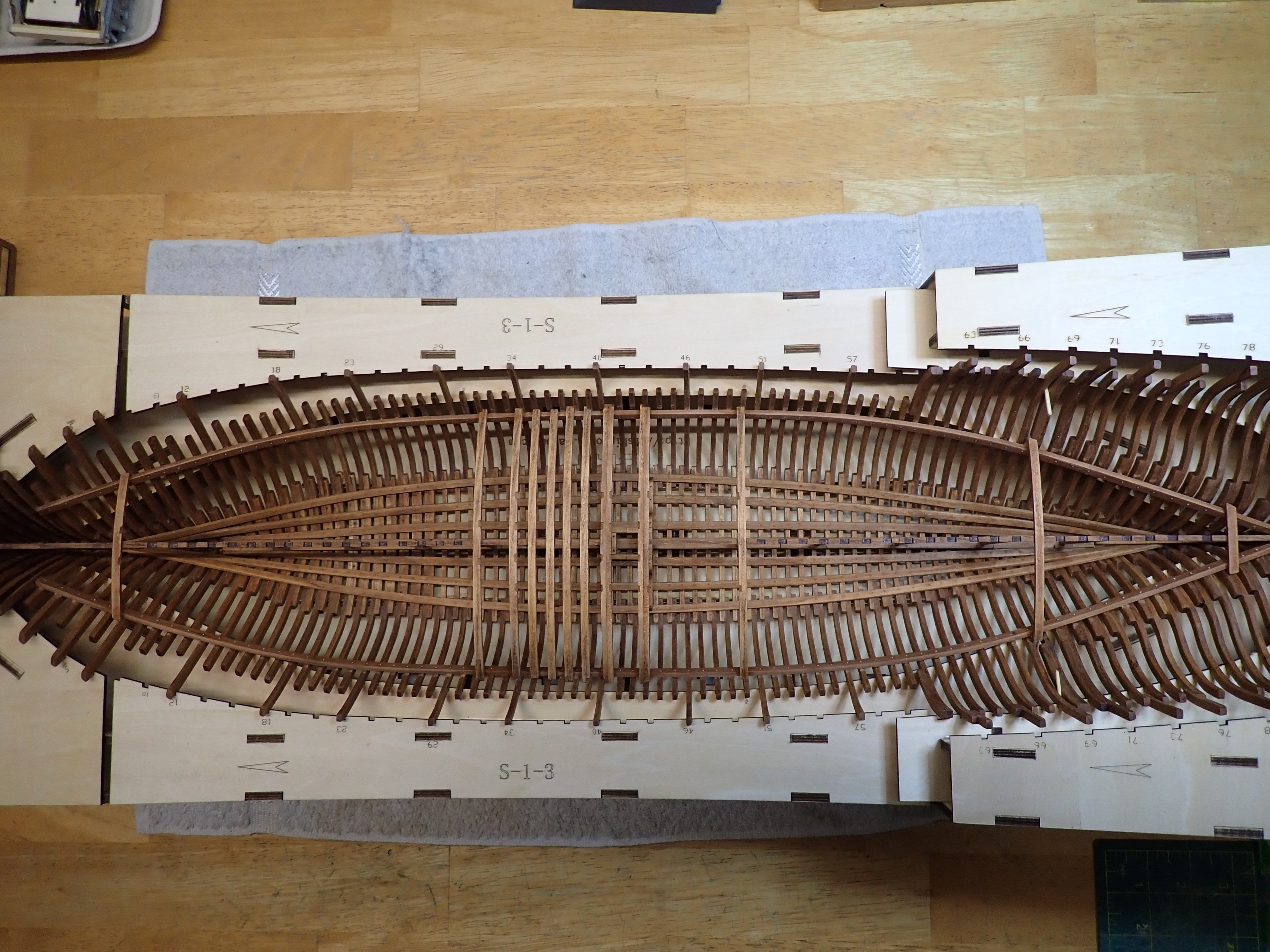
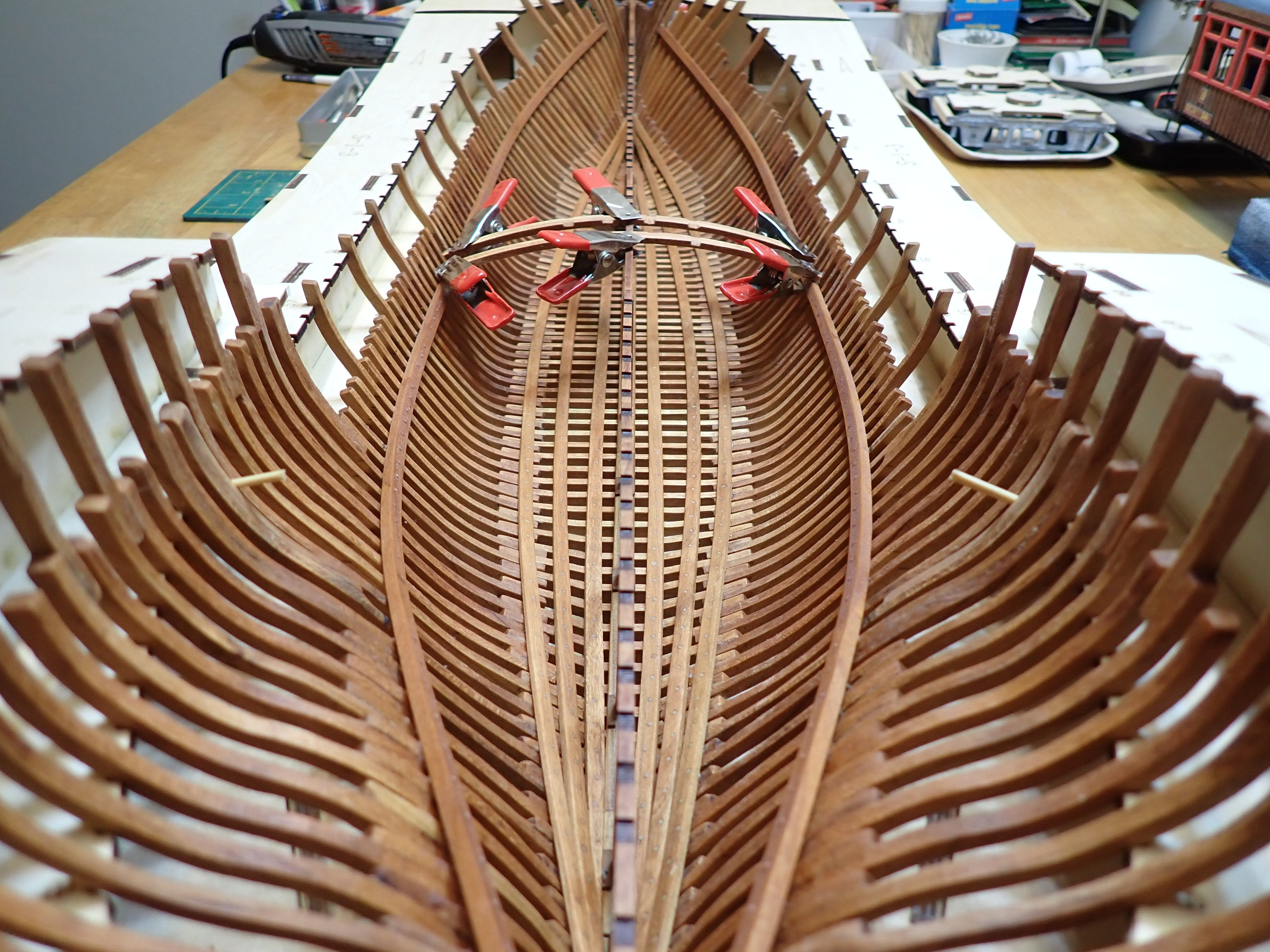
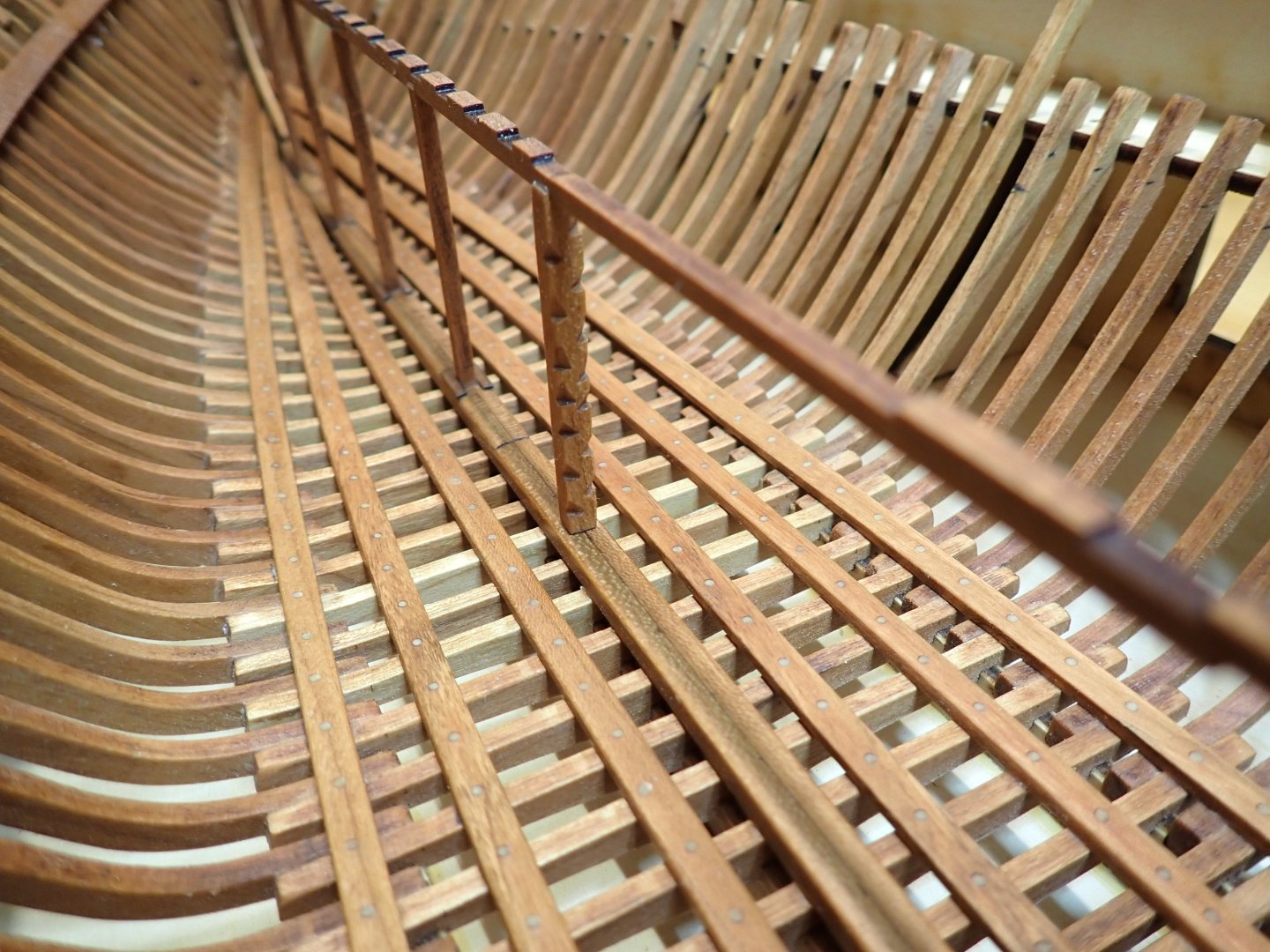
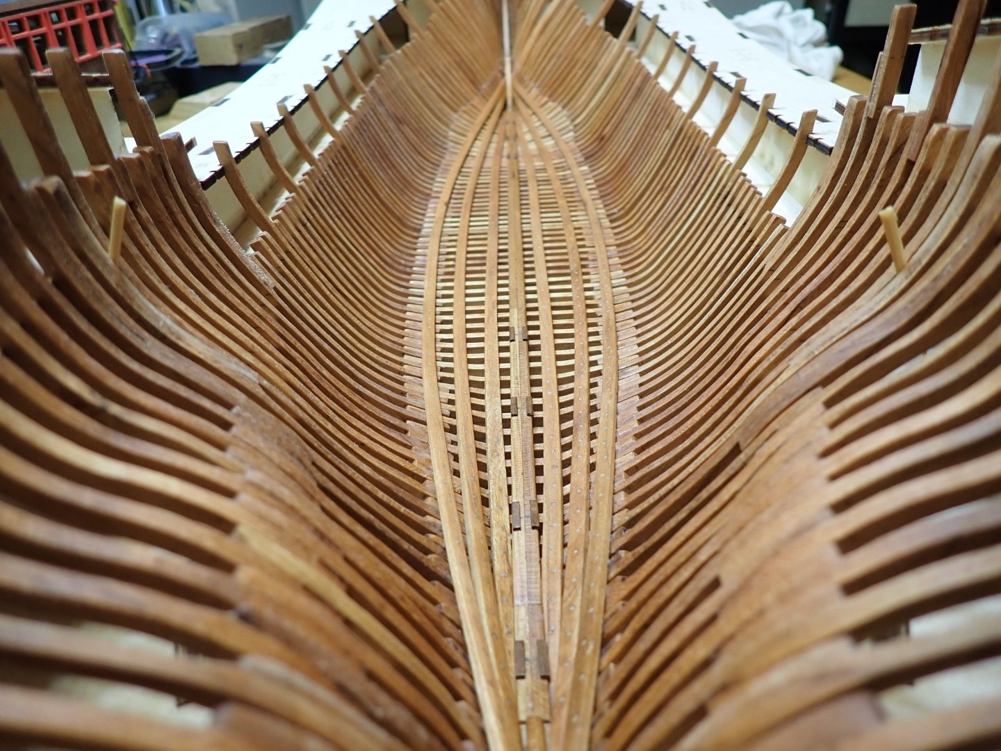
I just finished installing the third (and last) set of inside planks. Even though the kit calls for 5 sets, I am limiting myself at that point as these are extremely difficult to set correctly, since you have to hold the planks with your fingers while the glue does its job. There is absolutely no room to fix the planks, with perhaps the exception of drilling a small hole and placing a few microscopic wood screws. Again, all planks were tree nailed, with the tip of the nails protruding into the frames. The next part of the assembly is very complex, poorly documented by CAF and very tricky. It will drive the rest of the assembly and I hope to not screw up royally on this one. Yves

- 185 replies
-
- 15
-
-
Very nice workshop. Yves
-
Yeap, these Japanese modelers are perfectionists. They are incredible. I am always amazed when I try to build a motorcycle kit, at what Kinichi Karube is capable of doing in the scale of 1/9th: http://kimshouse7015.com/index.html Yves
-
Titebond will not work for ABS to Wood bonding. Instead, use Testors Green tube or even a glue such as UHU Hart if you can find it. Also, make sure the ABS has been sanded and cleaned to remove any de-molding agents and offer some grips for the wood. Yves
-
I am glad that you decided to plank the hull. Calypso is an old minesweeper and as such the hull was made of wood. The bow is made of metal, so be careful to not plank it entirely. Yves

-
John, Thank you for the links. The 3D virtual walk is amazing and renders so well the atmosphere of the ship. I have this kit in my stash and will take advice from your build log. Yves
-
WOW...putting together an engine at that scale is pure torture.... an expensive one on top of that 🙂 That Lancia is a great car and a very rare model. Yves
-
These old Revell kits are probably among the most difficult to assemble correctly. I have done a few and must say that. You are doing a terrific job with your Arizona and it will pay off later on. After doing such an old Revell kit, any modern Trumpeter kit will be a breeze in comparison. Yes, the art on the boxes is just wonderful and I know a few people who just collect the boxes for their artworks, knowing that they will never touch the plastic parts inside. Yves
-
WOP is Wipe on Poly, a chemical distributed by Minwax: It may be difficult to find in Europe and cost about $20 a small bottle in the USA. It provides a nice finish to wood and creates a thin layer of polyurethane on the surface of the wood, while also adding a subtle change of color to the light woods. Personally, I love it and have used it on my previous models. Yves

-
I like the markings on the serpentine/fan belt. Yves