Check out our new MSW Sponsor Innocraftsman
×


SJSoane
-
Posts
1,646 -
Joined
-
Last visited
Content Type
Profiles
Forums
Gallery
Events
Everything posted by SJSoane
-
 Hi Michael, I missed this project during my retiring and moving hiatus. Nice work, and beautiful jigs and tools that you are so good at creating. I look forward to seeing the next steps after a shop move! Mark
- 749 replies
-
- 3
-

-
- albertic
- ocean liner
- (and 2 more)
-
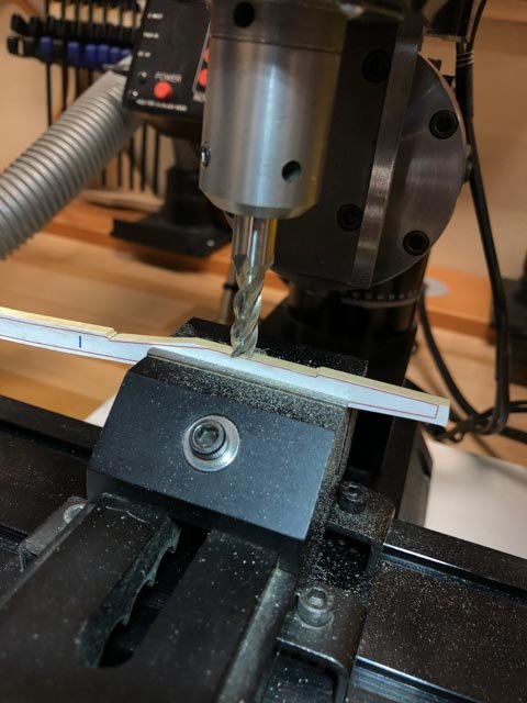
Thanks, druxey, Michael and Albert. I am constantly fighting my natural tendency to "bodge" through things, rather than being more methodical. Methodical is more satisfying for me. After playing around with various ways of cutting the hooked scarphs, I settled for now on using the Sherline mill to trim the inner flats, the disk sander to trim the outer flats, and the curved sanding blocks for the outer edges. I decided to keep the outer edges a little fat so I can trim these once on the hull. three parts fitted, 53 to go... Mark
-
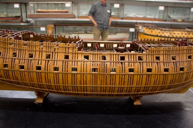
Alan, It really shows how large those timbers were... Mark
-
Gaetan, Replacing jointer knives always challenges me, because the last tightening of the bolts always shifts the knives ever so slightly. I appreciate seeing the skill with which you adjust and use your tools. Mark
-
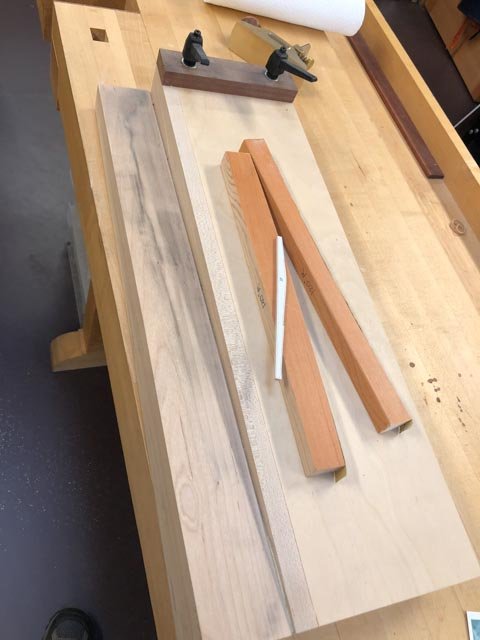
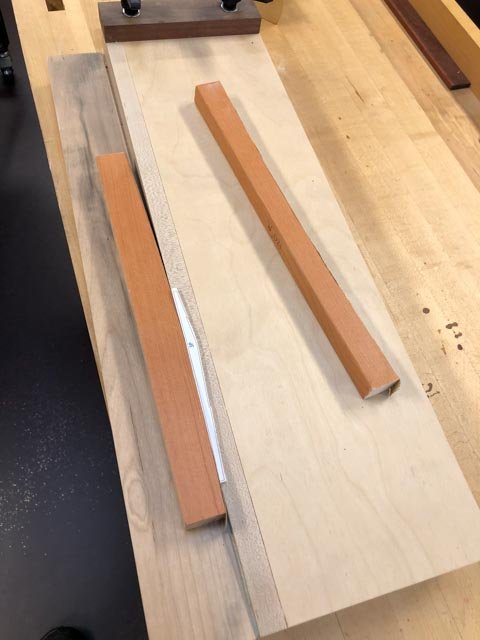
Yesterday I managed to cut out all of the wales parts. To refine the curved edges, I cut a sanding template to the radius of the wales in sheer in the center, and I am using this with my shooting board. The shooting board has a sloped ramp for the sanding template, which means a wider surface of sanding paper is presented to the piece as it slides back and forth, using the sandpaper more efficiently and avoiding grooves in the piece. Mark
-
Hi Ed, Truly remarkable level of detail and craftsmanship. You continue to set the standard. And I really enjoy your summaries of the functions performed by the various parts. In conjunction with the clear photos, it helps reveal the logic of these exceptionally complex machines. Mark
- 3,618 replies
-
- 2
-
-
- young america
- clipper
- (and 1 more)
-
Hi druxey, Thanks, I now remember seeing ledges like this in contemporary drawings, but did not understand what they were or why they appeared in certain places and not others. Now I see the logic once I tried to solve the problem myself. One of the great delights of this endeavor, for me and I am sure others, is to reconstruct the logic of the construction from the evidence of the historical record. Mark
-
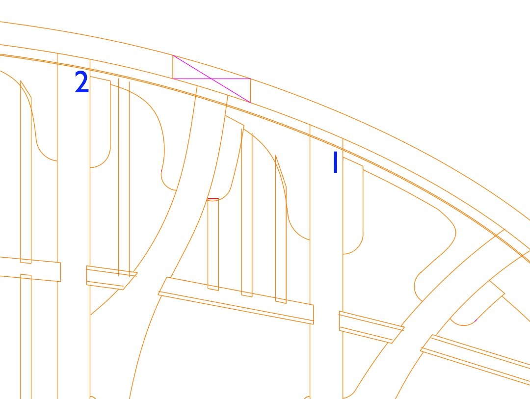
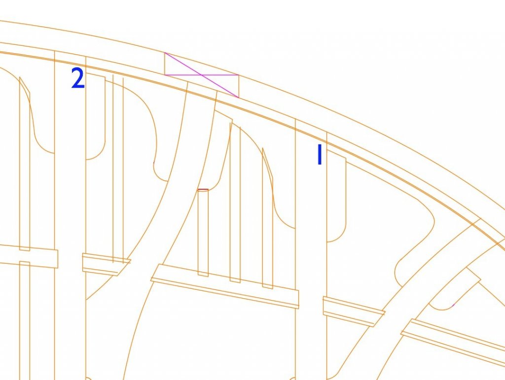
I had to put the wales on hold for a while, waiting for the delivery of replacement thrust bearings for my bandsaw (shame on me, I discovered while tuning my bandsaw after my move that the bearings had completely frozen up). Keeping busy, I continued with the conversion of my drawings from hand-drafted to CAD, working on the upper deck plan. I came across an unusual arrangement, which raises a question. The Bellona has two curved beams in the bows, one fore and one aft of the foremast partners. These form unusual spaces that need to be filled with ledges no closer than 9" or greater than 12" apart. As I have drawn this below, just aft of beam 1, one ledge is landing on the head of the hanging knee, which I have not seen in any contemporary drawings. Has anyone seen this, or is there another arrangement for this? Also notice the space fore of beam 1 , with a lodging knee at an acute angle. I am thinking this knee would have to be scarphed together from two pieces, but I have not seen this in a contemporary drawing either. And a ledge is likely to land on the two arms of the knee. No problem with that as I can think, but very unusual. Thrust bearings arrived yesterday, hope to be making sawdust again soon. Best wishes, Mark
-
Gaetan, Since your model looks like full scale, it particularly makes one think about how the shipwrights managed to hoist, install and fair up those very large, complex stern timbers. It looks great. Mark
-
thank you, Gaetan and druxey. There is no end of subtlety and variety in this ship construction tradition. Mark
-
Ed, that is really impressive metalwork, particularly at that scale.
- 3,618 replies
-
- 5
-
-
- young america
- clipper
- (and 1 more)
-
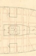
I started looking more carefully at the upper deck framing and the knees we just discussed. In the continuing spirit of noticing things I did not notice before, I see in the Dorsetshire (1757) upper deck plan some very curious deck beams, where the three part scarphed beam has the center piece on the opposite side from the two other pieces, forming a wavy beam. Has anyone come across this, or have an idea why this might be? The full print can be seen at: http://prints.rmg.co.uk/art/492743/dorsetshire-1757 Mark
-
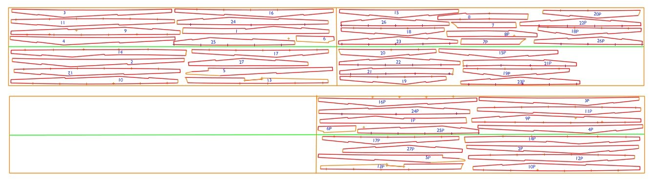
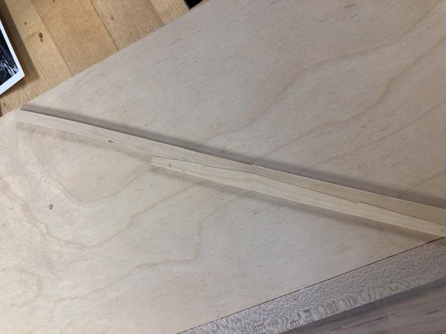
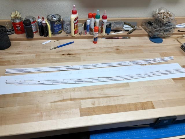
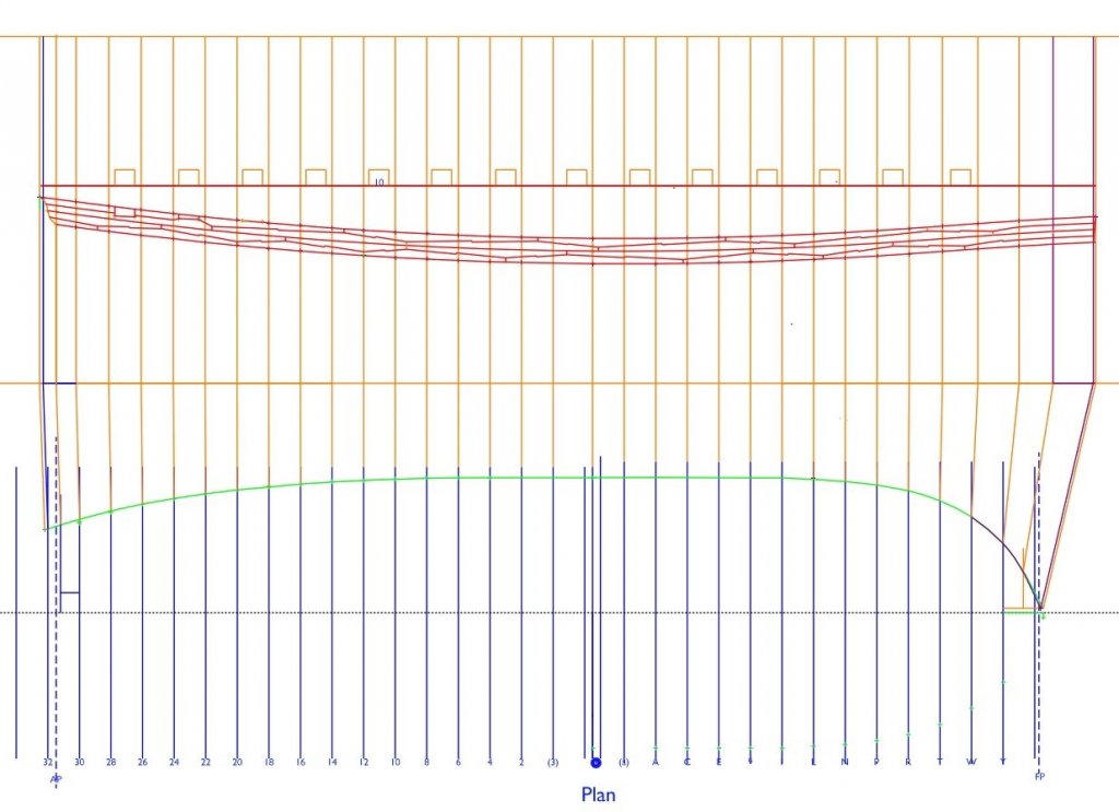
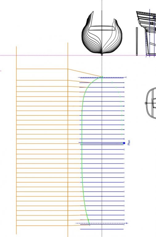
Those trees come from a mysterious place. A nice by product of expanding the wales in CAD is that I was able to create a very efficient template for cutting out both port and starboard pieces. These are laid out on the actual size of my blank, and the green line below shows where I have to cut down the middle to fit my thickness sander. Mark

-
So those could be compass wood knees. Some of those are from very twisted trees! Gary, I can't remember, did you get as far as installing those knees? Mark
-
Beautiful work!
-
Gary and Mark, very nice! It also shows druxey's idea for the aft strake, but with a little scarph to cut down the length. Also interesting are what appear to be iron hanging knees inboard, or are these compass wood? they look thin for wood. I don't think the Bellona would have had iron in 1760, but maybe? Mark
-
Mark, Gary, druxey, it makes all the sense in the world that the individual planks would vary in length to suit the wood available, and to ensure landing on a frame. Andy by extension, ideal proportions of 1/3 to 2/3 on top-and-butt, and 50/50 on anchor, could be adjusted by a foot or two to suit similar real circumstances in actual construction. So perhaps the Bellona model is showing reality more than an idealized model. I keep thinking that the starboard side of the model is demonstrating an unusual framing idea, compared to the conventional system on the port side. Perhaps the wales (which are only on the port side) are showing a conventional, practical system as well. druxey, I like your simplification of the upper strake. My drawing shows perhaps too large a piece for too little additional strength. Mark
-
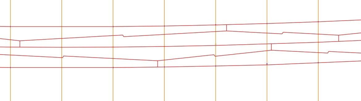
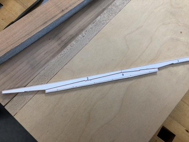
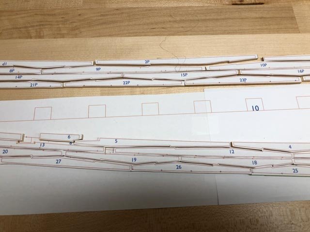
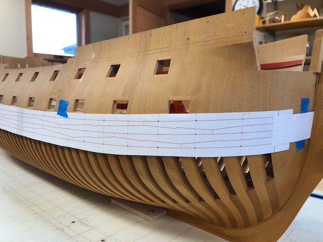
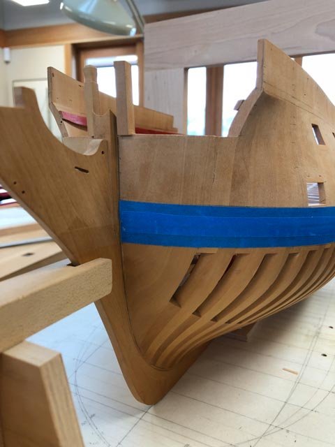
Well spotted, Mark, I never noticed the backwards hook! The lesson I will take from this is to draw each piece ahead of time, so I don't get distracted and cut one of mine backwards. I am wondering about my apprentice theory... I printed out the wales from the CAD drawing and taped it to the hull. I was off in length by 1/8th of an inch (too short in the drawing), so I adjusted by marking the actual station lines on the paper and readjusting the station lines back in CAD. All is now good to go, except for wondering if the aft-most gunport would be allowed to cut into the second strake down as shown in the second image without adjustment. Best wishes, Mark
-
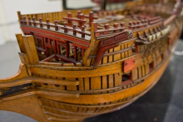
Gary, great to hear from you. Hope things work out for you to pick up the Alfred again. And you have a wealth of information for us all. And thanks, Greg, I will check out the Pandora model. Mark, could you point out for me where the hook is backwards? I confess that I looked at the model for the locations of planks, but drew my own hooks in without reference back to the model. So I missed seeing the mistake in the model. I became fixated on creating the wales on the Bellona exactly as they were done on the first model, using the various photos of that model to match joints to framing and gunport locations. The pattern that emerged from this exercise was surprisingly messy. The pieces "anchor" fashion were sometimes, but not always, equal length arms; sometimes one arm was 12-16 inches longer than another. The "top-and-butt" arms were sometimes a proportion of 1/3 to 2/3, but not always. The top two strakes were a more regular pattern of similar sized top-and-butt, but the bottom two strakes were a mish-mash of different sizes top-and-butt and some anchor thrown in. Was this real practice, or a quirky model builder? Some contemporary drawings of planking show a little more regularity. The butt ends of four planks coming together in one place on the Bellona wale seems structurally weak, and Mark discovered a backwards hook on that model. Maybe the apprentice did the wales on this model, and I am trying to reproduce a novice's first efforts at wales 250 years ago! Oh, well, it will be what it will be, as best as I can build it. Thanks, everyone, for your help with this.
-
Thanks, Ed, druxey, Alan and Mark, for the ideas and comments. We had visitors today, and spent most of the day driving to Glacier National Park in northern Montana. But in the early morning and late afternoon, I managed to finish up the drawing. Using a combination of CAD and a version of druxey's shuffle around the corner, I think I got a fairly accurate expansion. Mark, thanks for the note on the hooked joints. I have guessed from proportionally measuring the photos of the Bellona model that the hooks are 2 1/2" long, and incline 30 degrees to the line drawn between the two ends. Let me know if you have a different understanding. This should be very interesting to construct! Best wishes, Mark
-
Ed, that sounds like good advice. I measured the physical length of the wale between two station lines in plan, and plotted this on the true length line. It doesn't measure the true length along the slight curve between the station lines, but probably close enough. I only need this for templates for cutting rough blanks, and the finished parts can be refined on installation. Mark
-
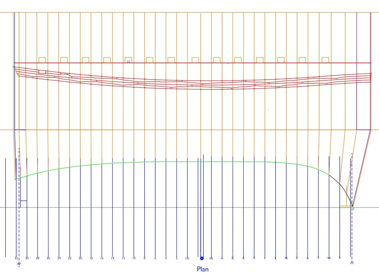
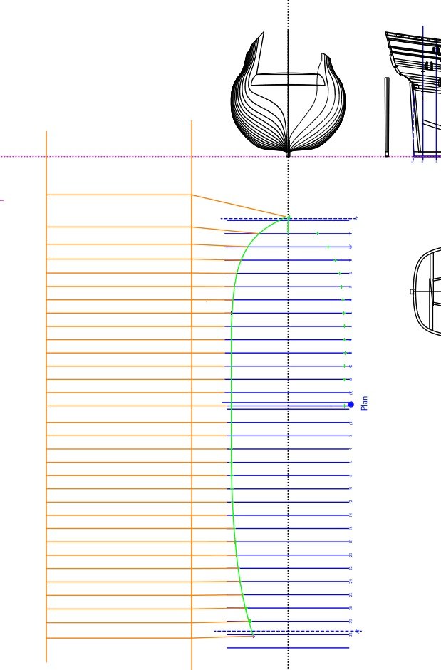
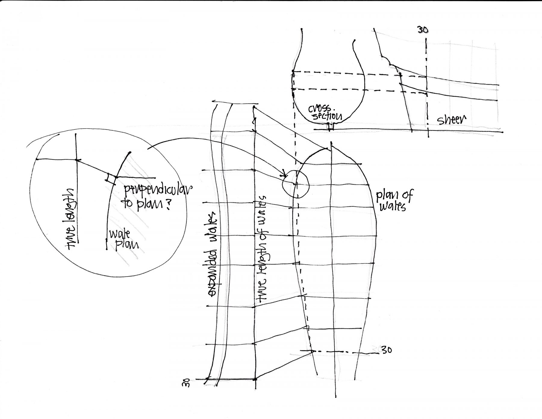
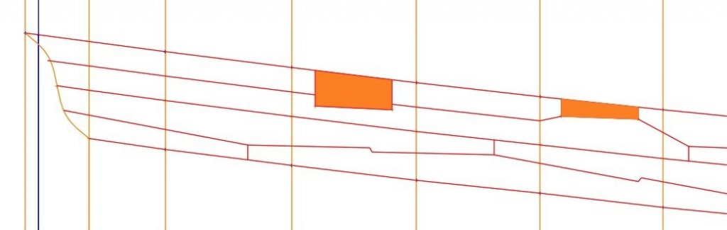
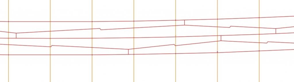
With so many individual wale pieces with many different dimensions, I decided to draw an expanded elevation of the wales, from which I could make accurate cut templates. However, my architectural background did not prepare me for how to do an expansion of a curved surface. In the drawing below, how are the station lines in plan projected to the true length line? Do you draw a perpendicular from the wale in plan at each station line, to the true length line, as I am showing in the circled detail? It seems it would make the wale way too long right at the rabbet in the stem, since a perpendicular there would be almost parallel to the true length line... Best wishes, Mark

-
Tiziano, I just came across your project for the first time. Beautiful, crisp work. Mark
-
Yes, indeed, I had the marks at the rabbet a smidge too high. I think they are parallel now. Easier to see in a photo than staring at the model itself. .. Thanks again, Druxey.
-
Yes I noticed that as well. The value of photos! I will double check some points off the sheer and see what is going on. Thanks for checking! Mark