


SJSoane
-
Posts
1,655 -
Joined
-
Last visited
Content Type
Profiles
Forums
Gallery
Events
Everything posted by SJSoane
-
 Gary, sorry to hear about the channel mix-up. I look forward to the updates, when undoubtably the planking will be even better than the previous because you have now had a practice run! Mark
 -
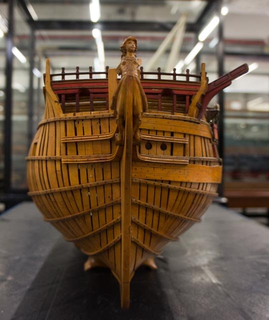
I forgot to mention, thanks Siggi, for the spectacular photos of bows. These are the kinds of images that keep me going, because I am reminded just how beautiful these ships and models are when they are completed. And it looks like more models are now on display at Chatham and Greenwich? The last time I was there a number of years ago, there were very few compared to the massive numbers in the old display at Greenwich before the museum was renovated. I had pretty much given up on Greenwich. Mark
-
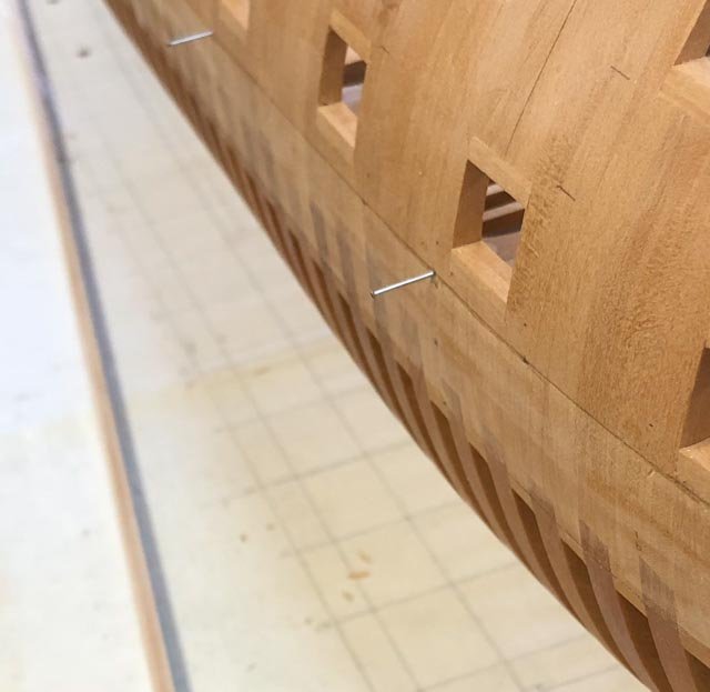
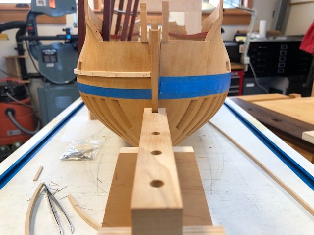
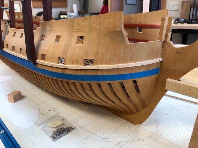
After recalibrating my gantry for measuring off the sheer drawing, I decided it would be prudent to re-plot the wales, just in case things went astray during the move. While I was at it, I re-thought how to attach the batten above the wale, for more accuracy. I had previously plotted points the thickness of the batten above the wale, so I could see the points from above while attaching the batten (too hard to look for points under the batten, in the shadow). But this proved to be inaccurate; the batten itself was not completely the same width along its length, and I had now plotted more points against other points, allowing errors to creep in. So, instead, I drilled holes at the plotted points at the top of the wales, which I could see clearly without the battens in the way. And I then put small nails into the holes, using these as stops against which I could very accurately hold the batten while drilling and fastening it. This was a reminder to me that--at least for me--registering one piece against another is going to be more reliable than free-handing. Mark
-
Mark and Ed, I missed your comments before I just posted above. Ed, I take your advice to heart; attending rigorously to the drawing is going to avoid any visual ad hoc adjusting that will later get me into trouble. I am also reassured that the wale appears to be parallel to the top of the hull right at the bows, since that was also carefully plotted from the sheer. Interestingly, as I tried to figure out why my plotting on the hull was originally erroneous right at the stem, I double checked my means of measuring. I had been using a gantry like yours to measure from a set height above the hull. But I unfortunately discovered that in my recent move, the gantry came out of true. The top of the gantry is not completely parallel to the base, and sheer drawing relationship to the top edge of the board has changed slightly. I don't know if this is the increased humidity, or things got knocked, but recalibration is definitely necessary! Mark, I see what you mean about the original Bellona model. Yes, they did leave off the topmost, foremost strake, I believe to avoid running into the temporary batten in this demonstration model. So I am definitely working to the top line of the wale taken from the sheer drawing, and I will be planking with four strakes in the wale. And it is a joy to be able to work on this more fully in retirement, although I still don't get as much done as Ed does in a day. He sets a standard to which I continue to aspire!
-
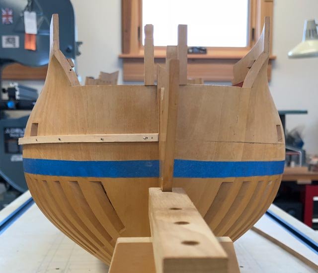
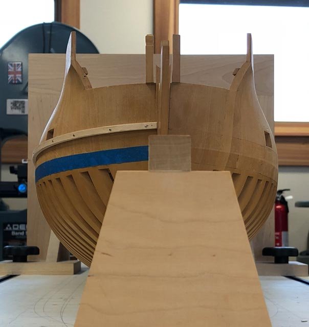
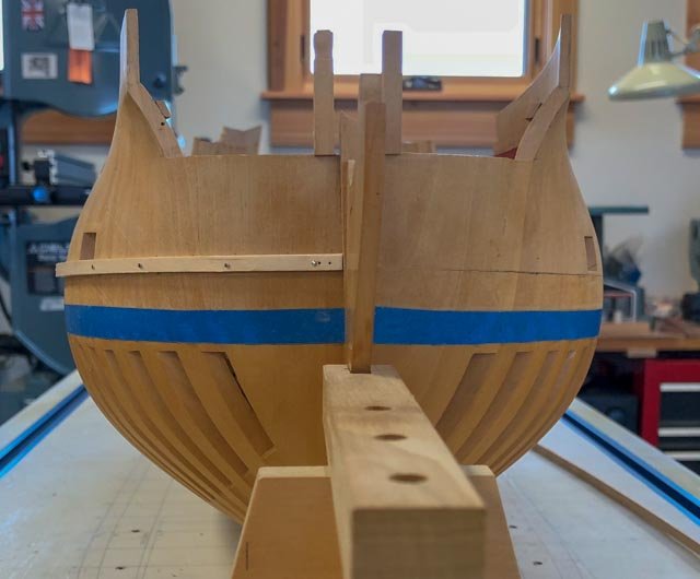
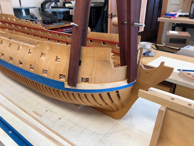
Thanks, Gaetan, Siggi and druxey, for your thoughtful help with this question. I worried in the middle of the night, because all of your examples, and my own of the Bellona, show the two wales coming to the stem at an acute angle, not as a horizontal line as my previous photo showed. So after more careful measuring, which continued to confirm my location, I realized that it had to do with the angle of the photo. As I show below, dropping the camera down reveals that my wales also come to the stem at an acute angle. And then I realized that the only way the wales could form a horizontal line from one side of the stem to the other would be if the bows were a perfect hemisphere at the stem. But since the hull is slightly pointed at the stem, the wales will have to form an acute angle. Mark
-
Hi Gaetan, Yes, the wale does make a double curve. i confirmed this more horizontal arrangement with careful re-measuring against the sheer, and also checking against the photo I took of the original Bellona model, where you can see the top of the wale on the port side is just about horizontal when it joins the stem. It is particularly interesting that the French wale you show definitely angles upward in comparison. This is all the more interesting because I understand that the influential Bellona design was derived from a captured French ship. I wonder if the original French ship had a sloping wale, and if the British adapted the French design to their own traditions in some places. Best wishes, Mark
-
Astonishing detail, beautifully crafted. Mark
-
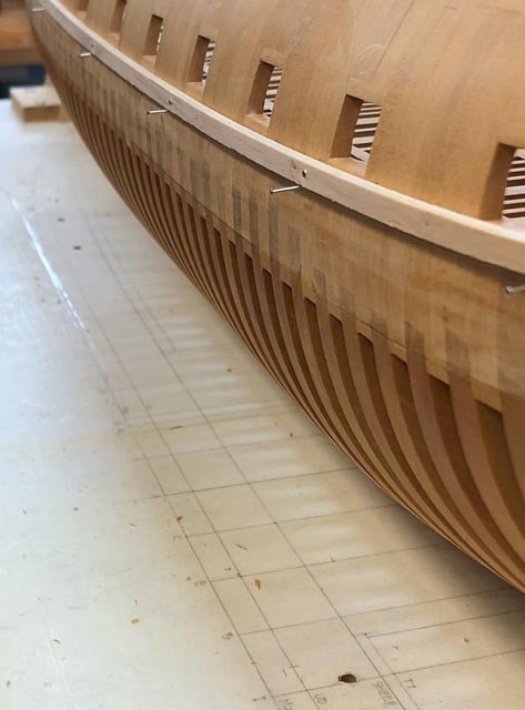
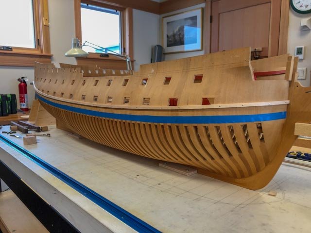
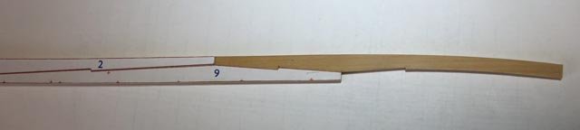
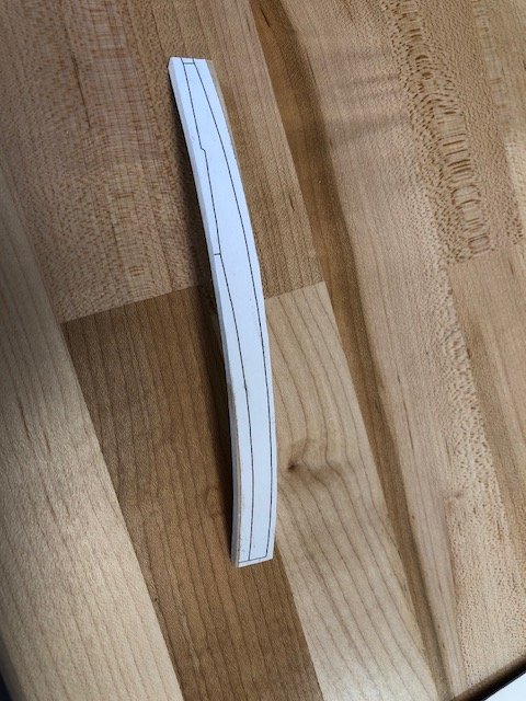
Thanks, druxey, you were right, the point at the stem had crept up. Here is the batten with the corrected curve. Gary's recommendation of a batten against which to set the wales is really proving to be a great idea. I was able to use it to accurately spile the topmost, foremost plank, and this showed me that there was greater curve on the upper surface than I had previously drawn (my CAD drawing had assumed, I realize in hindsight, that the surface was completely vertical, and this is not the case). The last photo shows how much the upper plank curves. It just goes to show that there is no shortcut to reliable techniques. Set a batten, and spile the planks, set a batten and spile the planks, repeat until this lesson is never forgotten! Mark
-
Hi Michael, I don't know, if the patrons could tip it again, you could stay working on this for a long time to come!🙂 Mark
- 749 replies
-
- 2
-

-
- albertic
- ocean liner
- (and 2 more)
-
Thanks, Gaetan, very interesting and informative! Mark
-
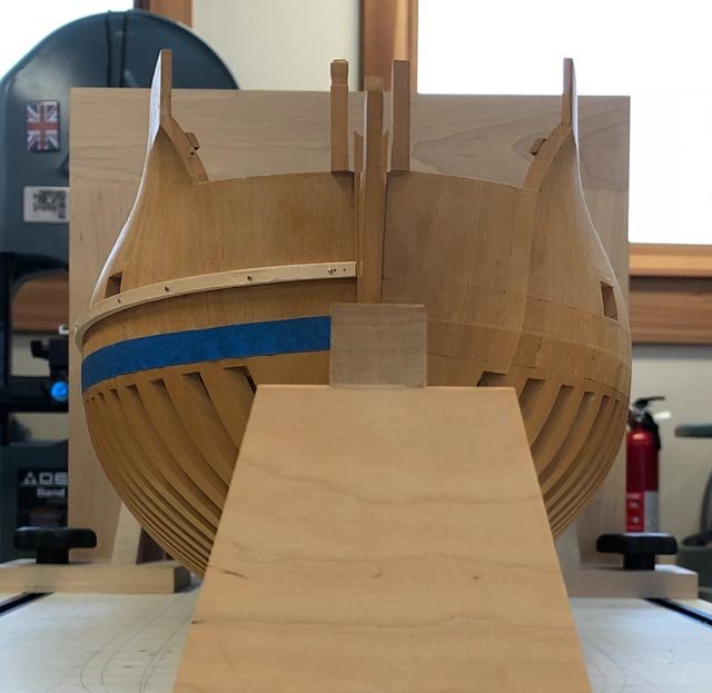
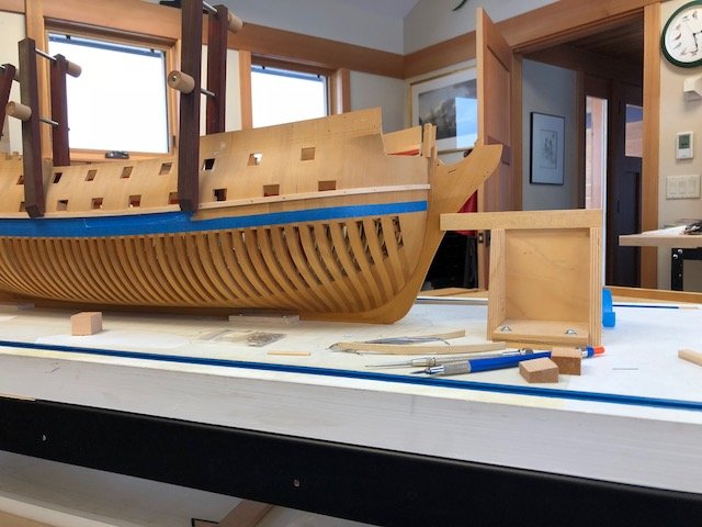
Here is a different angle view...
-
I forget to ask in the last post; should an imaginary line connecting the two wales across the stem make a smooth curve? Or do they come to a slight acute angle in relationship to each other? Since the sheer drawing has the wale as a smooth curve up right to when it hits the rabbet, I have been assuming that this would translate into a slight angle to the stem when seen from face on. Mark
-
Thanks, druxey, I will triple check it. I can't quite see if the batten, which is above the top line of the wale, is misleading me... Mark
-
Gaetan, Very interesting. Is that the while balance meter on the far left of your mount, with the colored buttons? And are those two light meters on the right? Mark
-
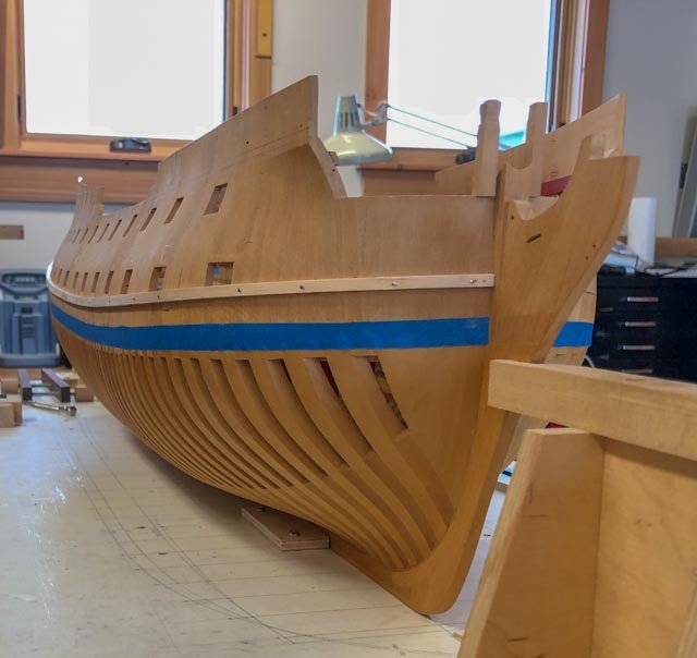
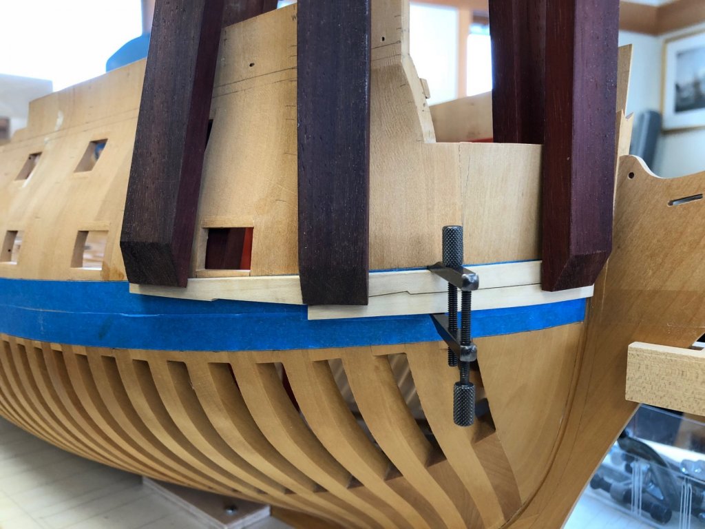
Thank you, aviaamator, the opinions of all of you really help keep me focused. Following the good advice of Gary on his Alfred build, I am installing a temporary batten at the top of the wale, against which I can fit the upper strakes for a smooth curve. Not quite sure yet if the pre-cut and then bent strake is going to fit tightly here. It needs some "encouragement" to lie flat against the compound curving surface, and I can't see yet if this will cause unreasonable stress. I am learning much at this critical place in the build; critical because it is so obvious if the wale lies correctly or not, and at the head where the viewer's attention will naturally be drawn when the ship is completed.
-
I pulled the pre-cut pieces off the formers this morning, and they bent very nicely to the hull. After pondering the not insignificant program of shaping a curved blank, I think I will have more success with the original plan of bending pre-cut pieces. This allows me to shape tight fitting joinery while pieces are still flat, then bend. There was a little more spring-back on the these pieces that I had previously boiled, compared to the blank I bent the other day that had not been steamed or boiled before. So the boiling did seem to affect the wood before the steaming. Only steaming from now on.. Mark
-
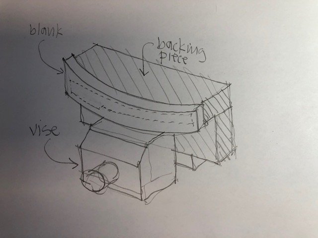
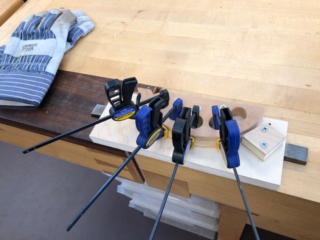
Thanks, Michael. I always appreciate your keen eye and ideas for tooling. Now I have successfully bent a piece, I need to think how I am going to shape it. I am thinking about attaching it to a backing piece that would allow me to clamp it in a vise, as shown in the drawing. Unless someone has a simpler idea. Just for fun, I steamed the original pre-cut pieces that I previously boiled and could not get to the right curvature. They appear to have bent to the former after steaming, as seen in the last photo, and we will see how much spring-back I get tomorrow morning. This is an impromptu experiment in the advantages and disadvantages of cutting and then bending, or vise versa... Mark
-
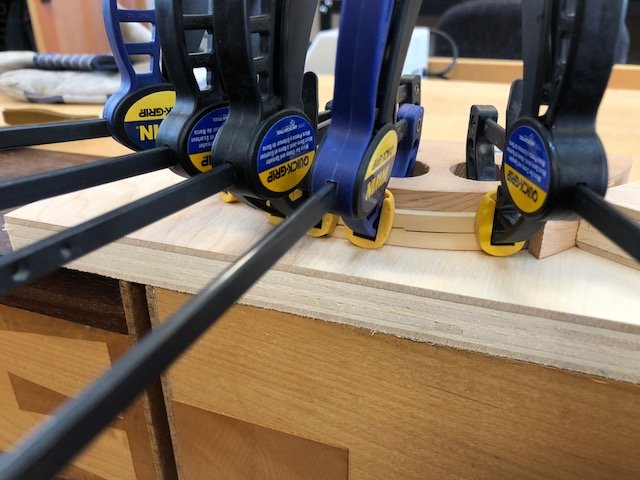
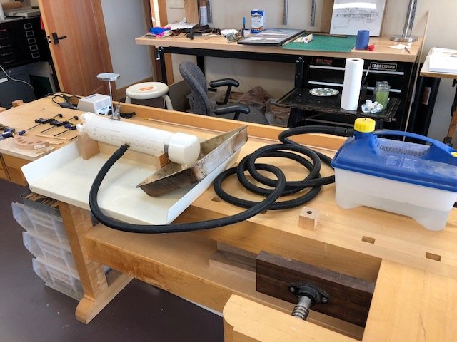
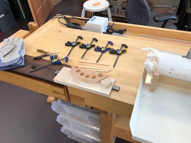
Thanks, druxey and Mark, I found a little guidance in the book, The Complete Manual of Wood Bending, by Lon Schleining. It recommended forming a curve around a male form only, so the clamps can progressively and smoothly pull the wood up to the curve. My earlier former tried to capture between two halves, and it did not work nearly as well. Mark, the holes in the PVC pipe are for a row of ¼" diameter dowels 1" O.C., which hold the steaming wood out of the condensed water in the bottom of the tube. The entire tube slants to a drain hole at the end opposite the opening, for getting rid of this water. This all came with the instructions I got with the steamer unit, which I found at Woodcraft a few years ago. There are also a number of instructions online, which would be more reliable than mine. I used a rag stuffed in the opening, fearful of creating a bomb with a tight fitting on both ends. The thermometer only got up to 115 degrees, while I was expecting more; but it seems to have worked. I used the formula of 1 hour per inch of wood, multiplied by 2 for kiln dried wood. Since my wale planks are ⅛", this was ⅛ hour times 2 or 15 minutes. It took about 15 minutes from cold to 115 degrees (I put the wood in the cold tube, before heating up), and then another 15 minutes or 30 minutes altogether from beginning to end. I let it dry overnight in the forms, and hit it with a hair dryer the next day just in case. Slow, but I only have to form curved planks from the wales up to the point where the hull flairs out for the catsheads. I am retired, plenty of time! ;-) I might make a few more formers based on the first, using a piloted trimming bit in the router table. then I could steam and clamp a number in the same session. Best wishes, Mark
-
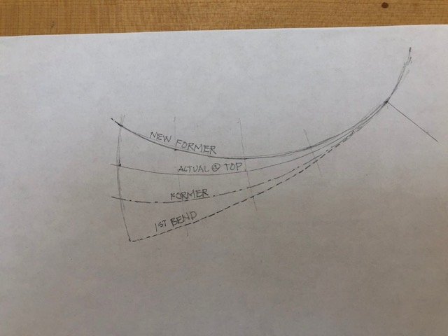
Santa did not bring a soldering iron or heat gun for me this year, so I turned again to the steam box parts that I had purchased a few years ago. I built a new box out of PVC pipe, scaled down to the sizes of wood I need to bend. I tried one former that was not sharp enough bend to allow for the springback, and then modified the bend more sharply to compensate (see sketch below). The final bend came out just right. I am in business! Mark
-
Nice, Gary, looking very good. I don't see your cannon; are those still going to be fitted on both sides of the gundeck? Mark
-
Michael, The more I see your clamping device in action, the more I really appreciate it. The time taken to design and construct a good jig or tool repays itself for the rest of one's life! Mark
- 749 replies
-
- 6
-
-
- albertic
- ocean liner
- (and 2 more)
-
Ed, those close-up photos make it look like the real thing. Imagine climbing out there in heavy weather... Mark
- 3,618 replies
-
- 2
-
-
- young america
- clipper
- (and 1 more)
-
Hi druxey, I got it over 20 years ago from Woodcraft, and it was labeled only as S.A. Boxwood, which I assume is South American Boxwood. Nice to work, very crisp, but is very stiff stuff. Gaetan, I have not had success finding the heating element like Gary showed (it might have been lost or misplaced in my move). Do you have a source for the one you showed here? Mark
-
Hi Michael and Gary, I had that plank bender a few years ago, and didn't have much success first time around. I 'll see if I can dig it out and try that. Michael, you showed a heat gun/soldering setup on on of your posts a while ago. Is that what you use for this? Thanks! Best wishes, Mark
-
Michael, Very nice work on the lines. I can see the dilemma; leaving the cruder repairs just doesn't seem shipright! Mark
- 749 replies
-
- 3
-
-
- albertic
- ocean liner
- (and 2 more)
