SJSoane
-
Posts
1,655 -
Joined
-
Last visited
Content Type
Profiles
Forums
Gallery
Events
Everything posted by SJSoane
-
 Another huge source of comfort is to read in Rob Napier's book, The Legacy of a Ship Model: Examining HMS Princess Royal", how the 18th century model makers made mistakes, sometimes small and sometimes very big! Realizing that took a lot of pressure off, no longer looking for perfection that even the masters could not achieve. Mark
 -
Michael, all the best for you and your wife. Family matters most of all. Mark
-
Siggi, A fast build, just three years! And looking very good. It is good to know that the capstan bars are stored between the beams. I like your rack for storing them. Mark
-
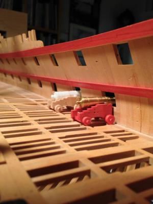
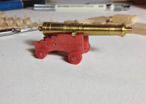
Hi Michael, thanks for the thoughts on holding it on pins. With paint it might work, but with stain I have to put a cloth on every surface and wipe it off. It is challenging. In the end, I had to mask each piece, and hold it while staining, then wiping. Tedious, but here are the first results. Ironwork still to come,, and I look forward to seeing the darkened pewter for cannon rather than the resin and brass seen here. Mark
-
Ed, exceptionally instructive techniques, as we have come to look forward to whenever you post... Mark
- 3,618 replies
-
- 1
-

-
- young america
- clipper
- (and 1 more)
-
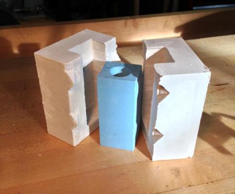
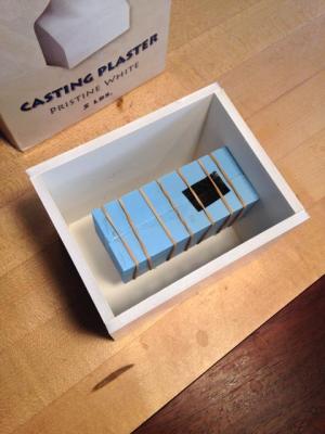
Thanks, bizibilder, I will try that on the gun carriages for the upper deck. I managed to cast a plaster holder for my gun mould as recommended in David Antscherl's Fully Framed Model vol. II. I now see the wisdom of that approach, after having my first pour spill out of the mould when the rubber bands burst. After the plaster dries, time to try melting some metal again. I also built a little jig for assembling the gun carriages. I haven't decided yet if I will stain each piece and then assemble, or assemble and then stain. Masking each part for separate staining in tedious, and I have no place to hold each piece when staining it all over, without putting my fingers in the fresh stain. But it is also difficult to get the stain into each nook and cranny when it is already assembled. I already tried it the first way, and I'll try it the second way tomorrow, and see what happens. Mark


-
Gaetan, Your cherry copy is spectacular! You are clearly a gifted artist. Mark
-
Ed, I just noticed (which shows how inattentive I am) the white on the bulwarks. I am facing the prospect of white later on in my build. Do you have any advice after trying this? Is this a paint or a stain? Mark
- 3,618 replies
-
- 2
-
-
- young america
- clipper
- (and 1 more)
-
Wonderful animation! Mark
-
Ed, You have this down to a fine art. You move so efficiently and with exquisite craftsmanship. Wonderful to watch. Mark
- 3,618 replies
-
- 5
-
-
- young america
- clipper
- (and 1 more)
-
Hi Siggi, I am following your studies of the cabins with great interest. I wish I had more information that could help. Is it possible that the cabins were simply canvas that could be rolled up out of the way, rather than solid frames? Mark
-
Remco, exquisite craftsmanship, as usual! Mark
-
Amazing, Michael. I would never have believed someone could hand build a spark plug that small, until I saw it in your video. Remarkable! Mark
-
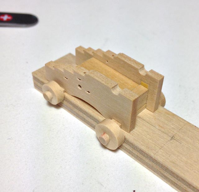
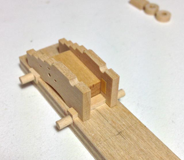
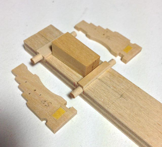
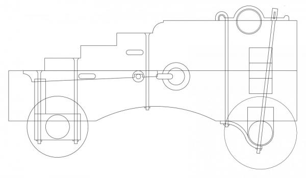
Hi Michael, Very interesting idea, breaking it down into parts. You are right; the wheel covers the joint and so no one would be the wiser. Here is a cross section of the carriage; you can see that there is a slight offset from the cylinder and the rectangular piece behind. At 3/16" scale, it is not very much. I had to use a #40 twist drill bit for the wheels, and so it would be the same for drilling into the rectangles for added dowels. This is a dumb question, but are there brad point drills that small? Otherwise, I don't know how I would control the tolerances on this without accidentally breaking through one side or the other of the rectangular part. Machining is a fascinating process. You learn new things on every setup! Best wishes, Mark
-
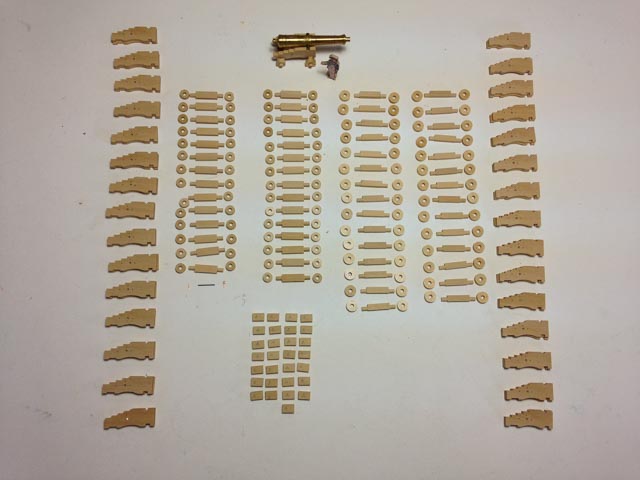
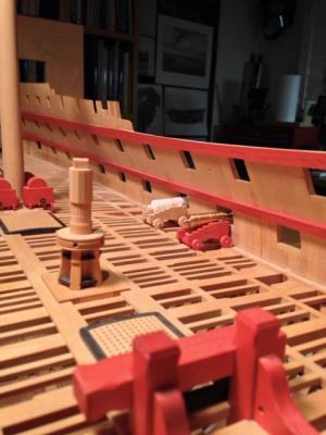
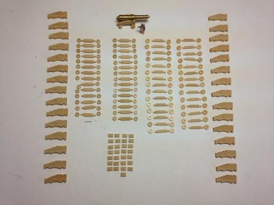
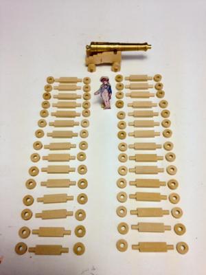
Here are all of the main wooden parts for 28 guns for the gundeck, 32 pound behemoths. I still need to make the stools and quoins, and drill a few more ancillary holes for attaching metal parts. And then there are the metal parts. But it is nice to have the main carriage wooden parts all ready to go. Thank you Stephen for your nice comment. A work long in progress! Druxey, very clever idea using round stock with a square hole. That would control both location on axis and depth. Next time I have to make this many pieces, I will try that. I have 46 more guns to go after finishing the guns for the gundeck.... I got the pewter melted at last, only to have my mould split apart during the pour. So back to more work on the mould.... Mark
-
Bizibilder, those are both very clever ideas. So in the first one, do you close up the brass tube all the way to the shape of the rectangle? Or is it enough that it gets to an oblong shape? Mark
-
David, nice idea about checking with the dead center. That would be much faster than my approach. I'll try that on the final 14 front axles today. Michael, you are a master machinist, including holding to tolerances I can only imagine doing; I look forward to your thoughts. Mark
-
Siggi, You know, I never thought to look behind Mars; all of our lost pieces might be hiding there! Mark
-
HI Gary, Thanks, that is very helpful. Those metal parts are very impressive! I am still struggling a little with casting the guns, and so then it is a nice break from that to work with another set of challenges, the small metal pieces. I look forward to seeing your progress on the Alfred when you can break free from work. Mark
-
I finished up the rear axles and trucks, except for drilling the retaining pins and rear eyebolt. I learned something interesting about much repetitive use of the four jaw chuck. I assumed that as long as I loosened and tightened the same adjacent jaws when changing blanks, the setting would always hold. But over time, the setting slipped and the cylinder was no longer centered. I had to throw away a number of pieces after I realized what had happened. So I had to check every five or so and readjust. Does anyone know a trick for tightening and loosening a four jaw chuck to keep the settings over a large number of pieces? I had backed off one side while tightening the opposite to center the piece, but then I tightened both towards the center before cutting. After time, one of the jaws definitely felt like it was backing off. I wonder if I should have left one backed off, opposite the one I tightened and loosened while changing blanks? Mark
-
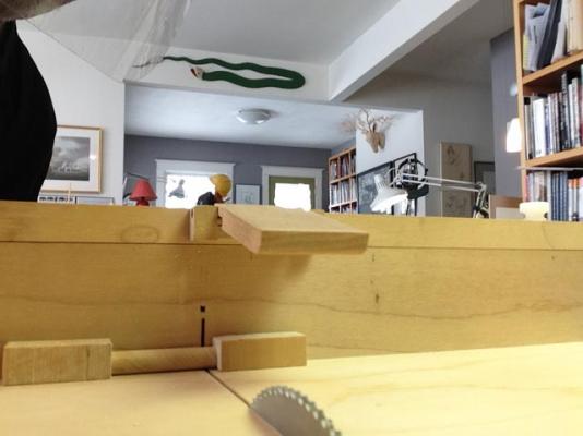
Druxey, so that explains why neither neither rubbing sticks nor peddling got me very far....;-) Greg, thanks for the Nobel prize. It is still a little fiddly to renew the double sided tape on the end of the small stabilizer piece of wood every 6 cuts or so, but it reliably keeps the cutoff on the table and out of the way of the sawblade after the cut. I once got lazy and did not renew it even when it was no longer sticking, and sure enough the snake on the wall ate my flying piece. I wonder what archaeologists in the distant future will make of all of the tiny abandoned machined pieces found lying around in the remains of our houses. I purchased the lathe depth stop from a small firm in Denver. It works really well. I also bought the additional end pieces, so I could stop very small parts. You can find it at: http://www.a2zcorp.us/store/category.asp?Cguid={E7EADB42-05AE-43E9-965E-4A4011A47E6A}&Category=LatheDepthStop:Sherline Best wishes, Mark
-
ROYAL CAROLINE 1749 by Doris - 1:40 - CARD
SJSoane replied to DORIS's topic in - Build logs for subjects built 1501 - 1750
Doris, beautiful, beautiful work! Mark- 883 replies
-
- 1
-
-
- royal caroline
- ship of the line
- (and 1 more)
-
Gaetan, Gorgeous, spectacular craftsmanship by you and spectacular French design by the shipwrights! Mark
-
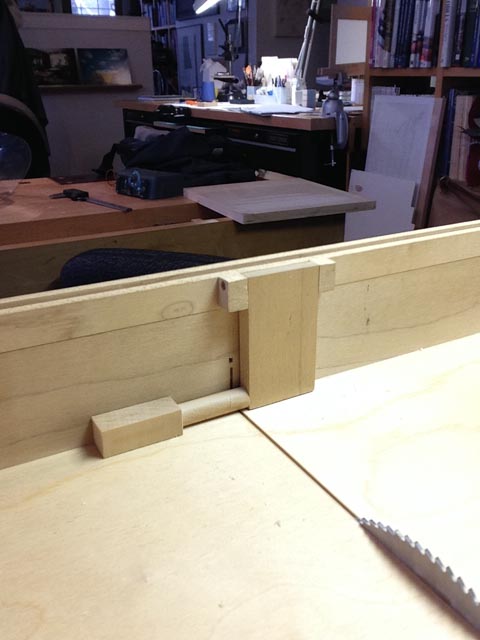
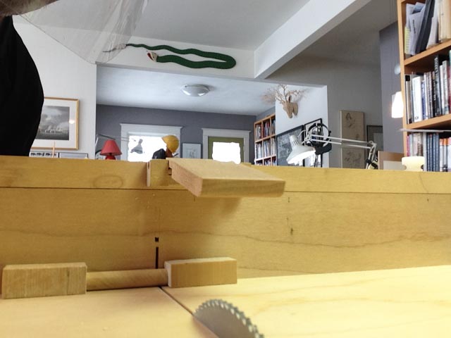
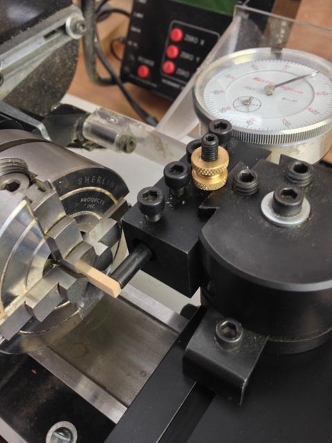
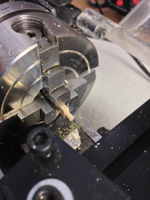
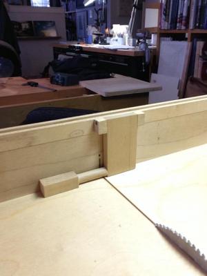
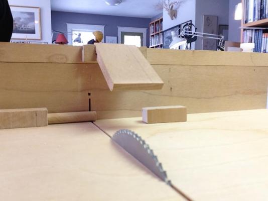
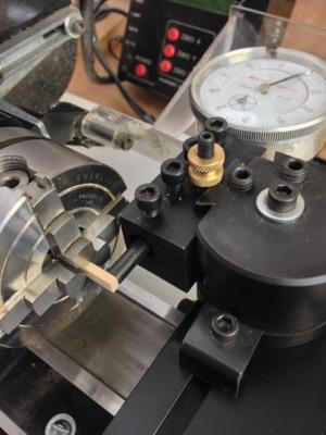
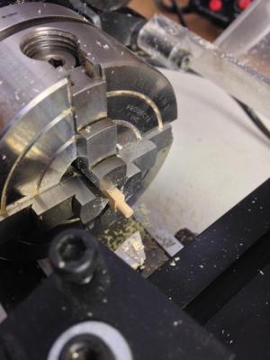
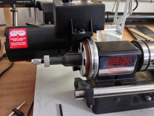
Hi everyone, I purchased something to melt my pewter; will try tomorrow and see what happens. Druxey, I wasn't peddling, I was rubbing sticks together very vigorously... Meanwhile, I kept working on carriages. I learned a few helpful techniques. The photos of the saw sled are showing how I have a flip-up stop to cut each truck to the same width. The stop has to flip up after setting the blank against it, so the cut off part doesn't bind against the sawblade after it is cut. But the parts fly away if not retained in some way. I finally hit on putting double sided tape on another small piece of wood; I push this up against the blank after flipping up the stop and just before cutting. When cut, both the truck and the small piece of wood gently slide aside, but don't fly. Ignore the snake on the wall in the background in the 3rd photo; it has nothing to do with where the loose pieces fly, I keep telling myself.... The photos of the lathe are showing a nifty setup for cutting the rear axles. The cylinder is centered in a rectangular but not square blank, and so a four jaw chuck is needed to hold the blank. Rather than trial and error getting the center of the cylinder aligned with the center of the lathe, I set it up with a dial indicator. I used the Sherline quick change tool post boring head holder, to mount my dial indicator to the Y table. I could then swing the opposite sides of each side of the blank towards the indicator, measure the discrepancy between the two sides, and then dial in the jaws until they were equally distant from the center of the lathe. The last image is showing an A2ZCorp attachment for the Sherline. A shaft goes through the center of the lathe head, forming a stop so that each blank can be inserted exactly the same distance into the chuck for repetitive cutting. All for now; thinking about melting pewter tomorrow at last. Mark
-
Thanks, Ed, this is very helpful. I think it might be the hotplate. I "borrowed" my wife's hotplate that looks like something from the 60s.....