

schooner
-
Posts
643 -
Joined
-
Last visited
Content Type
Profiles
Forums
Gallery
Events
Posts posted by schooner
-
-
-
Thanks Chris!
I'm a little surprised about how fast this is finally going after a year of seemingly minuscule progress.
Tim
-
Hi OC,
Detailing at 1/350 is beyond my capabilities so my hat's off to you. My next project will probably be a 1/350 kit of one of the ships I served on. It has been years since I worked on a resin kit and I can't believe how much they have improved, particularly the kits from Orange Hobby. There is an amazing amount of cast detail and at least 7 sheets of PE just for a FF! The kit's helicopter alone has about 30 parts. So although my next build will be highly detailed, all the work will be done by the manufacturer for a change.
Tim
-
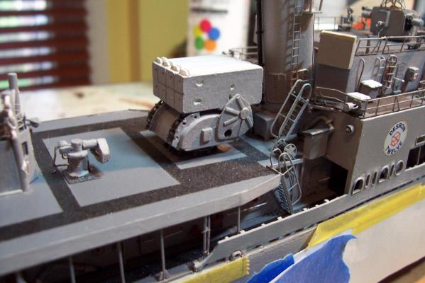
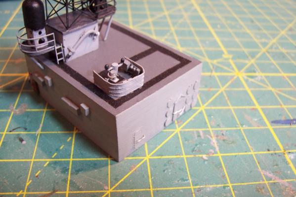
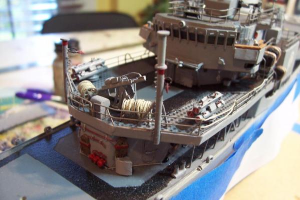
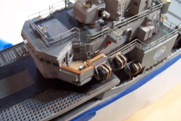
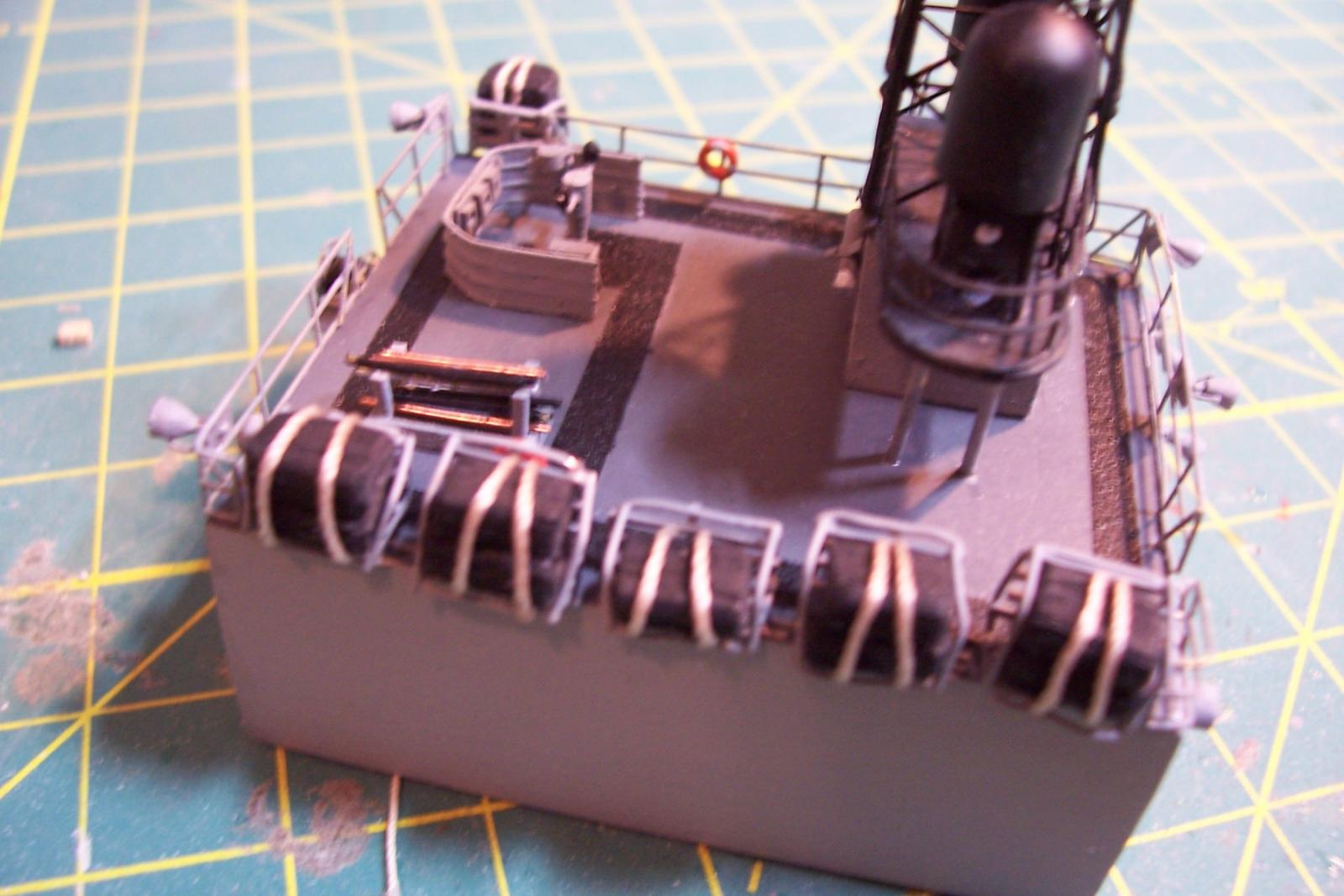
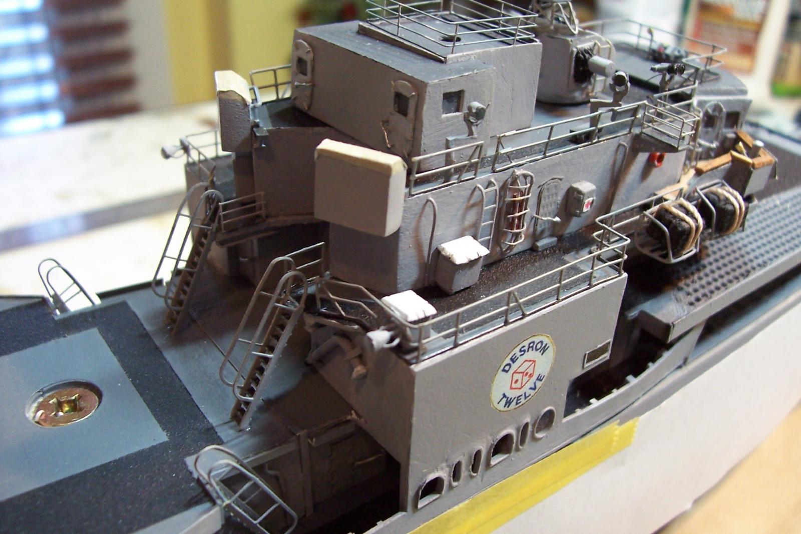
ASROC Deck
Added the stacks, ASROC Launcher, control station and various vents and lockers:
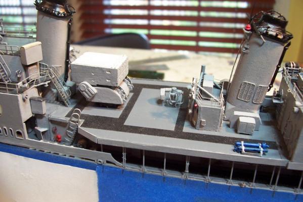

The railings will be added after the motor whaleboat and davits are installed.
Next up will probably be the flight deck nets.
- Ray, Captain Slog, mtaylor and 5 others
-
 8
8
-
Thanks for the kind words. When I decided to use this model to try for more detailing than I usually do I knew that I would have to do as much detailing as possible off of the model so that I wouldn't constantly be breaking stuff off as I rested my hands on something to steady them. The only drawback to doing it this way is I spent a long time with little apparent progress being made but now that the the sub-assemblies are being added the pace has really picked up. I just realized I will have to order the plexiglass display case soon so that it will be ready when the model is done.
- justsayrow and mtaylor
-
2
-
-
I just discovered this log. Amazing build! I love the way you made the cage masts, winches, guns, well ... everything in fact!
What is the cased ship model that appears in the background of some of your photos?
Keep up the great work.
Tim
-
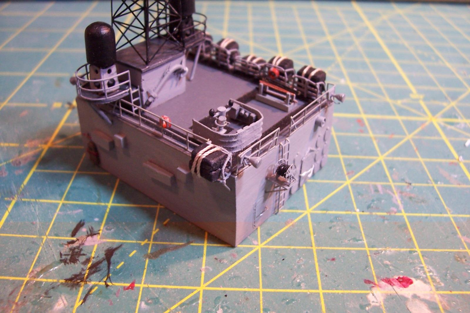
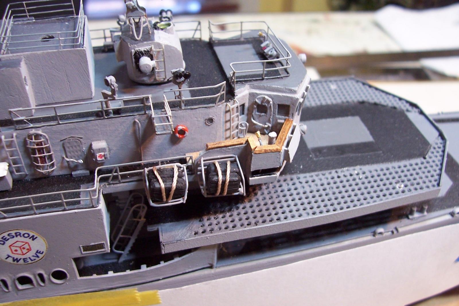
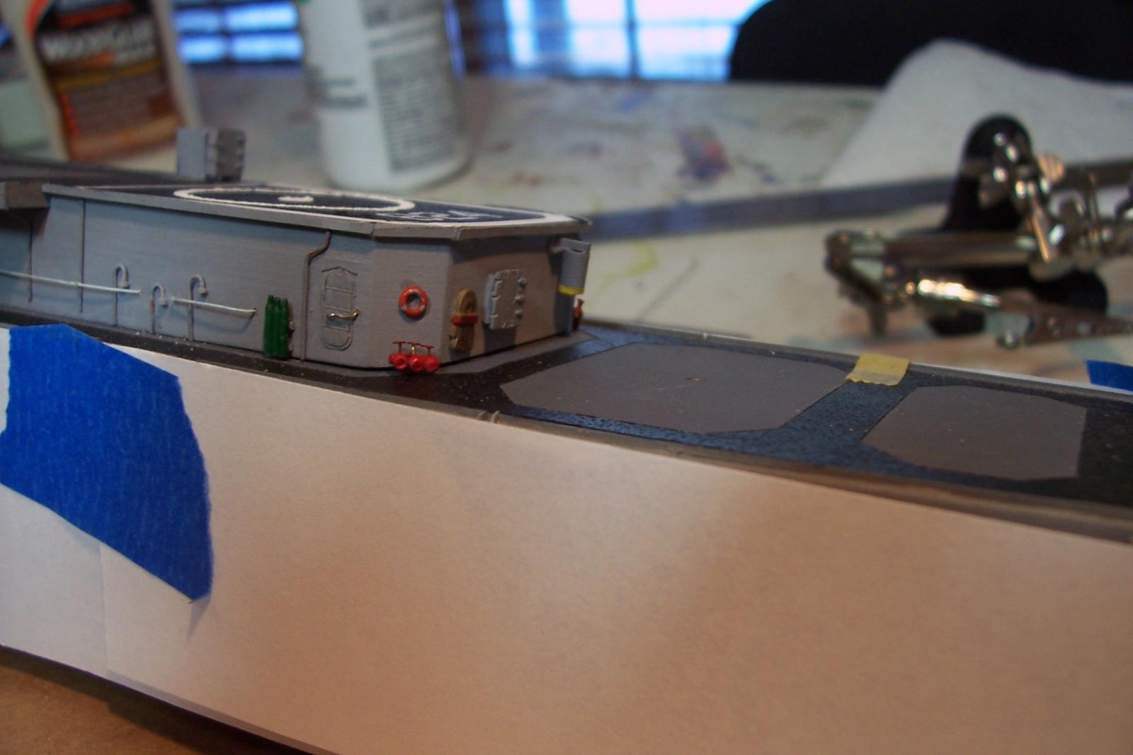
Secondary Conning Station
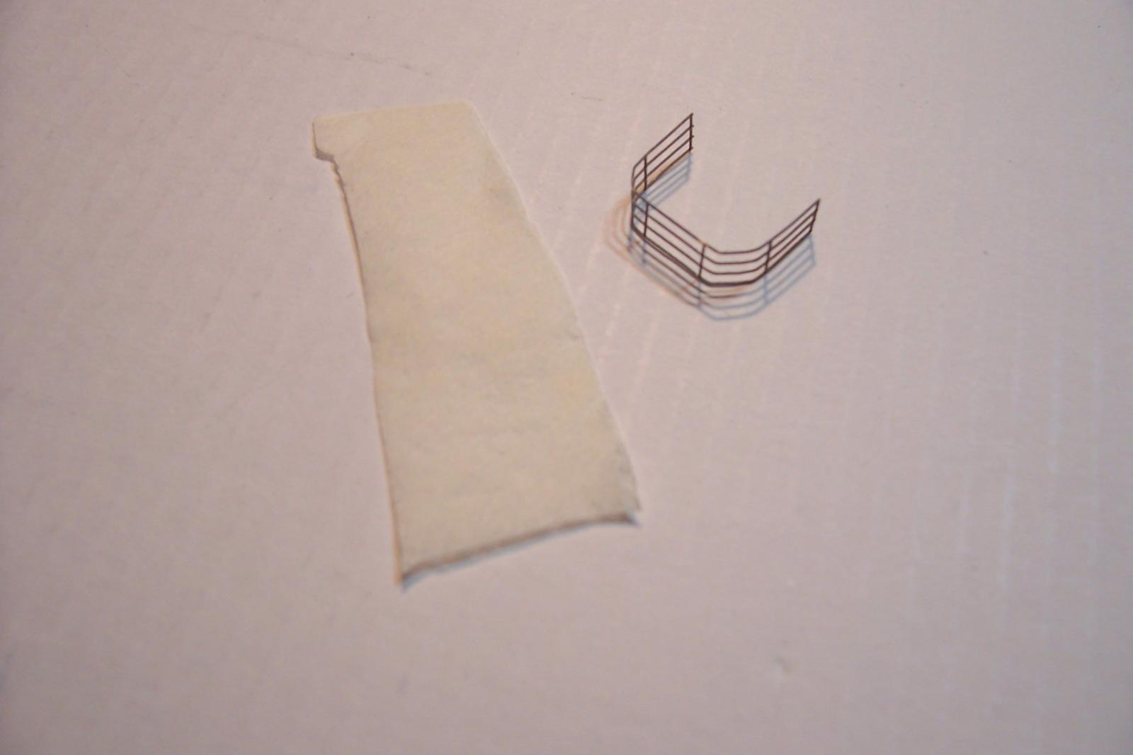
The first detail added to the DASH hanger is the secondary conn, where the ship could be controlled in the event the bridge was damaged. Usually located well away from the bridge and outside for good visibility, the secondary conn had minimal equipment.
I started by making the windscreen. The blueprints show it as a section of railing with a canvas covering. Bending a piece of PE railing was easy. I planned to make the canvas covering using some tissue paper wetted with diluted white glue so that I could get the “ribbed” effect seen on canvas wind screens.
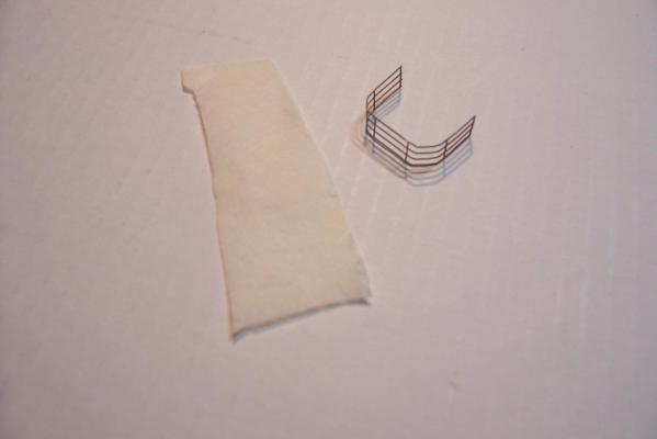
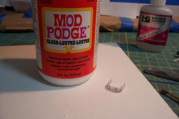
I was out of Elmer’s glue so I found some similar stuff that my wife has on hand for crafting. While brushing the glue onto the railing I was surprised at how well it formed a thin screen between the PE sections so I decided to let it dry and just paint that. I was further surprised that when it dried it was crystal clear so it looks like I have found a new glazing material to use on windows (in this photo it looks a little cloudy - it was not completely dry yet).
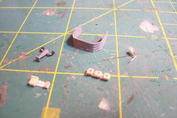
Here’s the painted screen along with the equipment that will make up the secondary conn: Kit-provided magnetic compass binnacle (shortened somewhat to bring it to scale), a gimbal mounted gyro repeater, S/P phone panel, and a set of repeaters for things like shaft RPM, rudder angle indicator, etc. After test fitting this last piece I decided it was too big and redid it in styrene instead of wood.
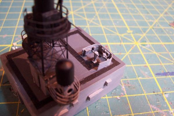
Here’s the finished product mounted on top of the DASH hanger:
- hexnut, justsayrow, GuntherMT and 4 others
-
7
-
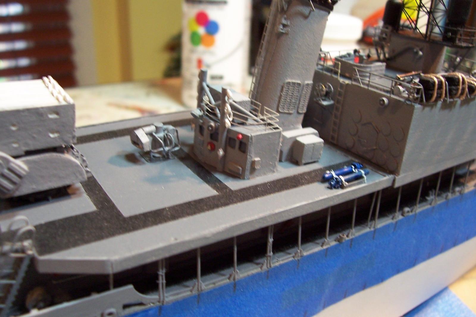
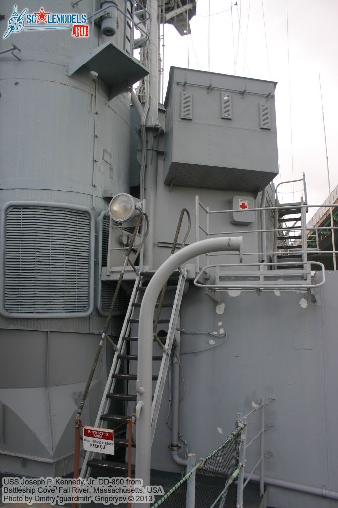
FWD01 Level Details
The primary scratch details remaining for the 01 level are the two antenna stub masts. Both serve as the anchor points for the bottom of 3-wire HF fan antennas and the port one also has a UHF stovepipe antenna mounted on it:
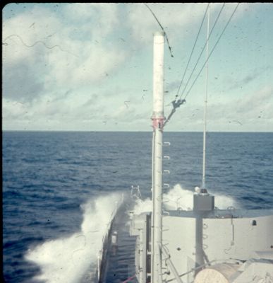
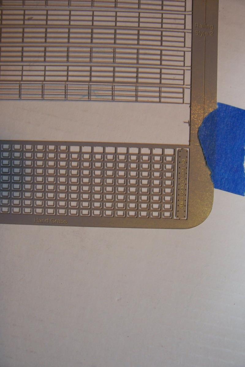
The stub mast had ladder rungs on them for maintenance of the antennas, fortunately Gold Medal Models’ 1/192 ladder fret has individual handgrip rungs along with a nice template for drilling their holes:
Trying to drill 2 sets of holes on a piece of 1/16” styrene rod was beyond my capabilities so I just used the template to mark their locations. Here’s the finished 01 level with the stub masts, line reels, 5/38 Practice Loading Machine, MK32 Torpedo Tubes, and the section of “pipe railing” (for lack of a better term) outboard of the fueling connections, used to keep the refueling hose from chaffing on the sharp deck edge:
Next up will be detailing the DASH hanger.
-
Boy ain't that the truth! When I finish this puppy I plan to spend 2 days cleaning it, then take lots of photos and then REALLY clean it, removing all the plastic bits, shavings, dog hair, etc that I never see when looking at it with what I though was decent eyesight.
Tim
-
Hi Ray,
Thanks for checking in. Building the Diana has always been on my dream list, just don't have the room for the finished build and its case.
A Hunt DD should be a great build, they were amazing ships. I can't recommend too highly the Waterline Warships book I referred to in one of my early posts, wonderful ideas on how to detail a DD (HMS Caesar) , even more relevant for a Hunt than a FRAM. Hope you start a build log when you start that one.
Tim
-
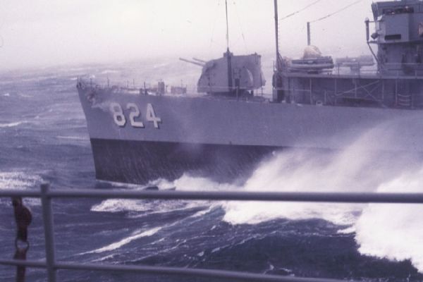
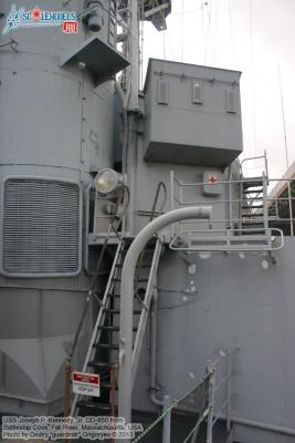
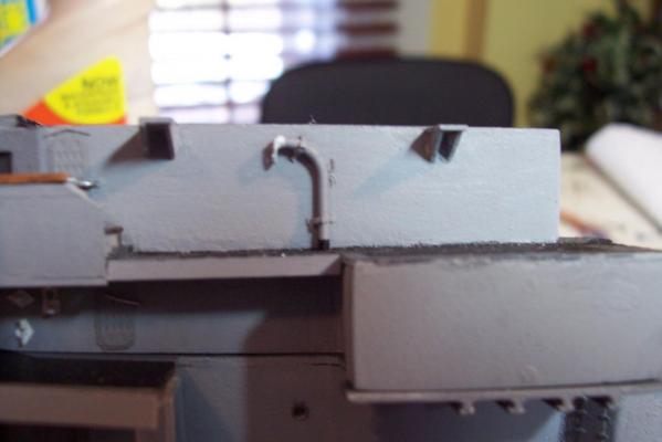
FWD Replenishment at Sea Kingpost & catwalk
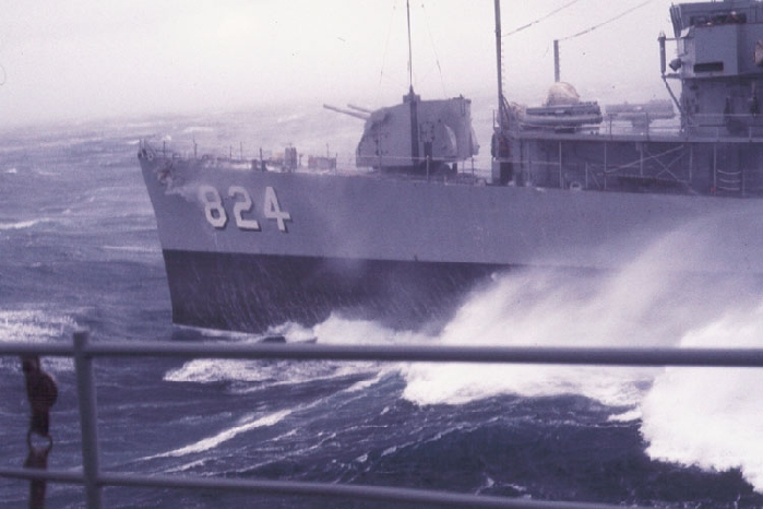
The FRAMs had a short portable king post that could be rigged forward of the bridge, either port or starboard. Here’s a shot of it on the Basilone.

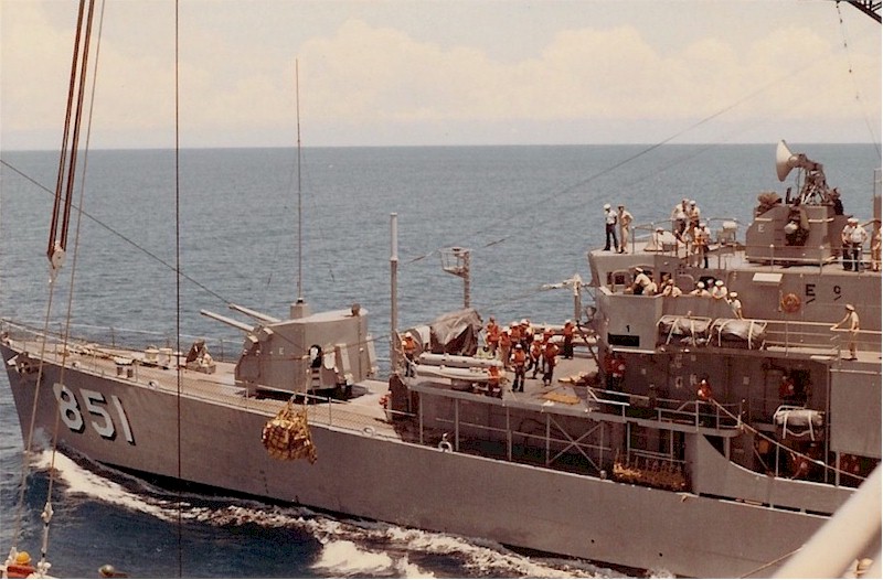
And here is one in use on another FRAM:
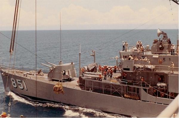
Although it does not look very robust it did not need to be since both the high line and the in-haul lines were hand-tended. When it was not in use it, and its braces were stowed in a rack on the front edge of a catwalk that was used to rig it.
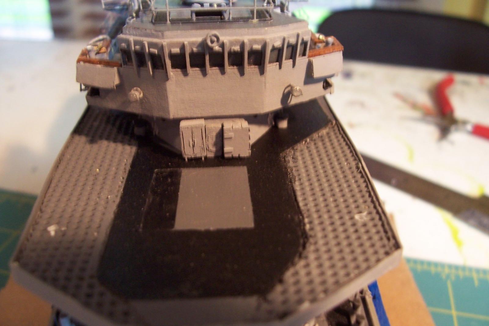
Before putting in the catwalk I scratched some lockers that were used for the 5” Practice Loader that will be installed on the 01 level later:

Here’s the various parts after being made from styrene:

Here’s everything assembled on the model:
Next up will be more detailing of the forward 01 level.
-
Great start! This was my first kit build too but you have waaay better tools than I had (or have). I enjoyed that build and learned a lot, hope you will too.
-
Main deck stanchions
One of the unique visual markers of the FRAMs was the widespread use of rather spindly deck stanchions between the main deck and 01 level. USN cruisers and destroyers of the 50’s to 80’s all had a least a few but none as many as the FRAMs. Deck stanchions have pretty much disappeared in more modern ships in an attempt to be more stealthy by eliminating such radar-reflection highpoints.
The stanchions are .020 wire per the kit instructions. My only additions are the deck drain pipes and gussets on the after groups.

Next up will be detailing the forward 01 level deck.
- Captain Slog, WackoWolf, hexnut and 4 others
-
7
-
Bridge level details
The kit provides pelorus’ for the bridge wings, they look good but when fitted on the model they are too tall (6 ft at scale). Although it would have been a simple matter to trim them by 3/32 or so I happened to have some smaller ones from Bluejacket in my spare parts kit that fit just fine.
Here’s the finished bridge level. Kit provided items include the deck gratings, vertical ladders, railings and the 2 lockers on the port side. The WTD's (without windows) are aftermarket, everything else is scatch made.


Next job will be installing the stanchions that run between the main deck and the 01 level.
- Captain Slog, rvchima, tarbrush and 5 others
-
8
-
Bitts & Chocks
The kit provides closed chocks and 2 sizes of bitts, all nicely done in Brittania metal. The sockets on the deck edges for the portable davits are scratched.

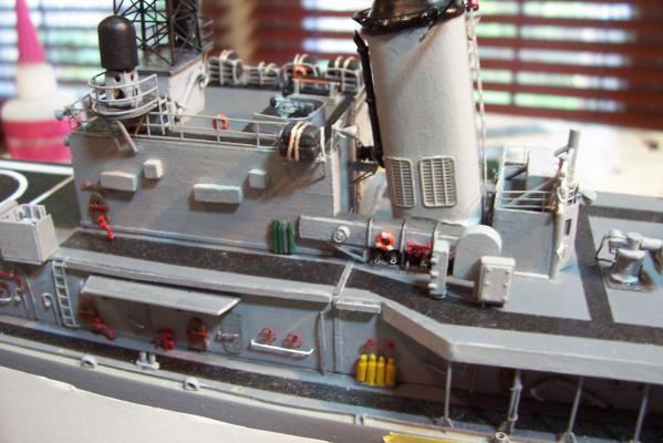
Signal Bridge detailing
I bought some 12” signal lights from HR Products, and while they look good from the front, when viewed from the top or side the lights have no depth, they are almost flat.
I cut out the lights leaving the yokes and cut plastic rod to size, flat on the front face and curved on the rear, added a dog-leg arm so the light can signal ships astern, and the shutter arms. I also scratched 2 “Big Eye” binoculars.

Here’s the finished signal bridge. As I mentioned previously, the Ops Office/Signal shack is scratched since on the Basilone and the other FRAMs modified at the Philly Navy Yard the structure is significantly larger than on other ships. The Sig shack is dry fitted and will be glued down when I step the mast. The pyro lockers, sound powered phone boxes, and the unusual knee-high instrument panel that constitutes the flying bridge, and its voice tube are also scratch additions.
Next up will be detailing the bridge level.
-
Hi Hekk,
Good choice for a starter kit. I built, in order, Midwest's Chesapeake Flattie, Whitehall Tender, and Skipjack. The directions on each were great teaching aids, showing you not just what to do but HOW to do it. By the time I finished those 3 kits I had the confidence and skills to tackle a POB sailing ship. Needless to say this stuff can get addictive.
Good luck with your build.
-
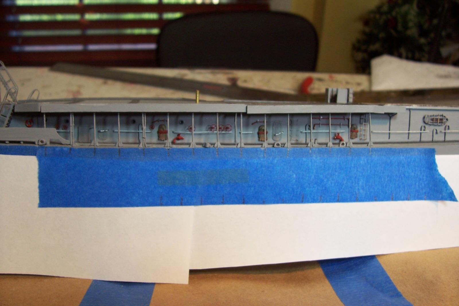
Amidships Bulwarks Re-Do
There’s nothing like a photo (however bad) to bring out the flaws in a model.
After looking at the pix I posted something was really bugging me about them - the gap I created at the bottom of the bulwark, while to scale at 12”, was simply too big.


Fortunately the thickness of the bulwark is a standard size for plastic strips so after a little reconstructive surgery I was able to reduce the gap to what I was after in the first place.

One step forward - One step back...
-
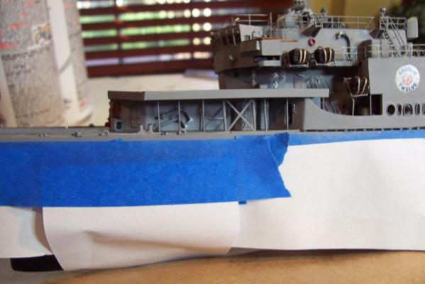
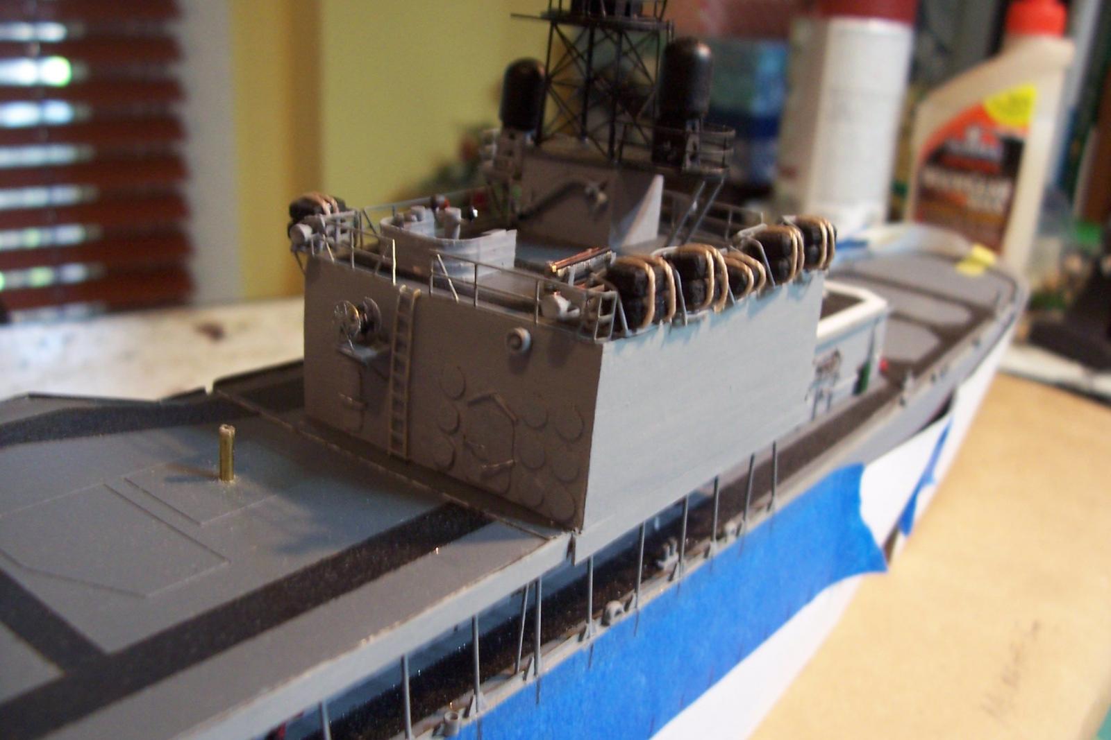
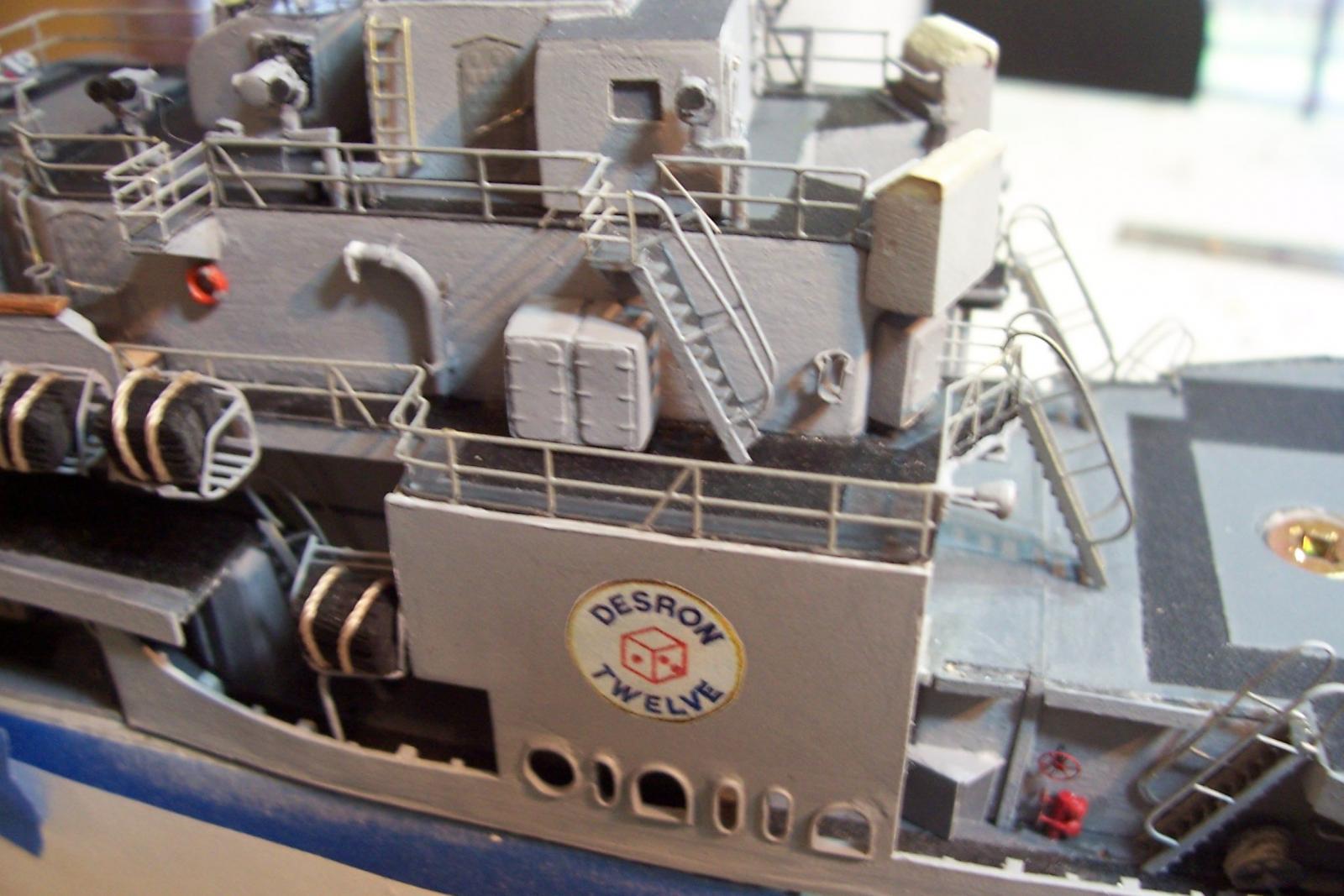
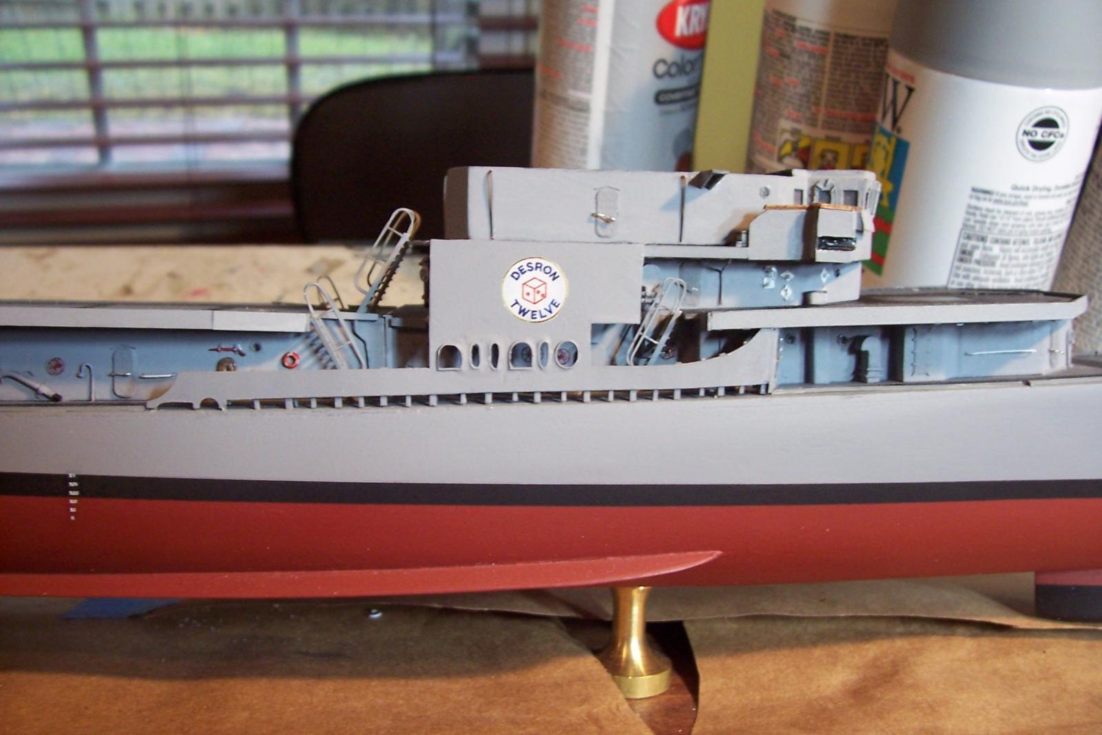
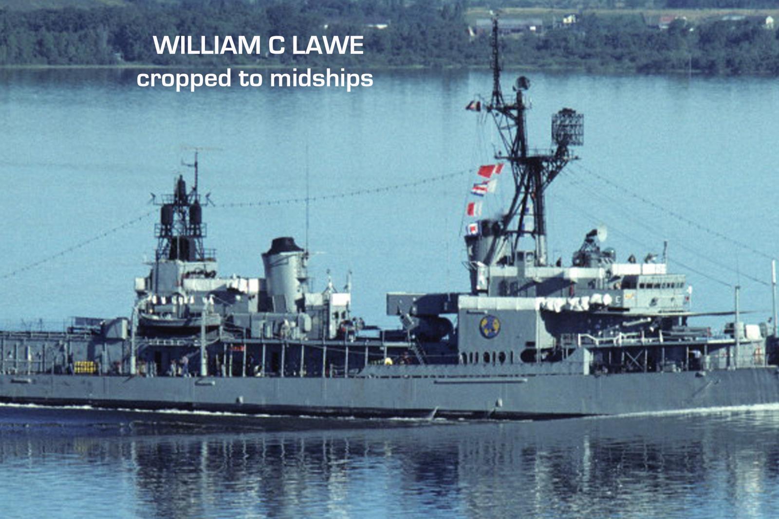
Amidships Bulwarks
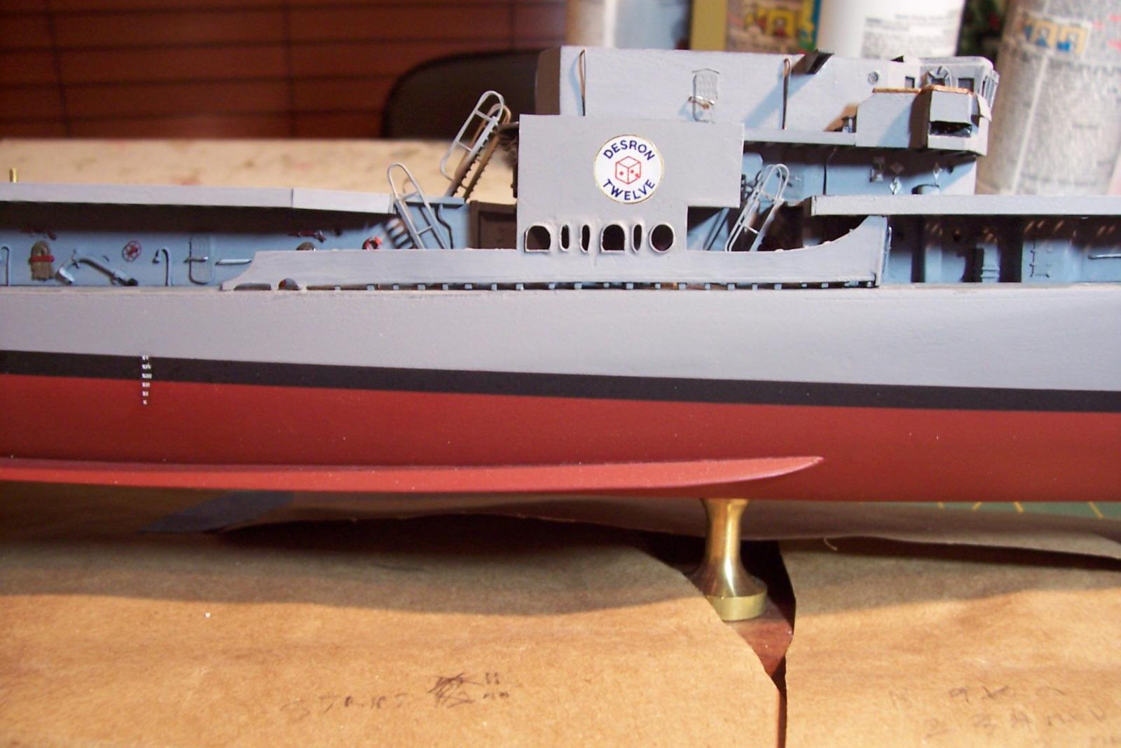
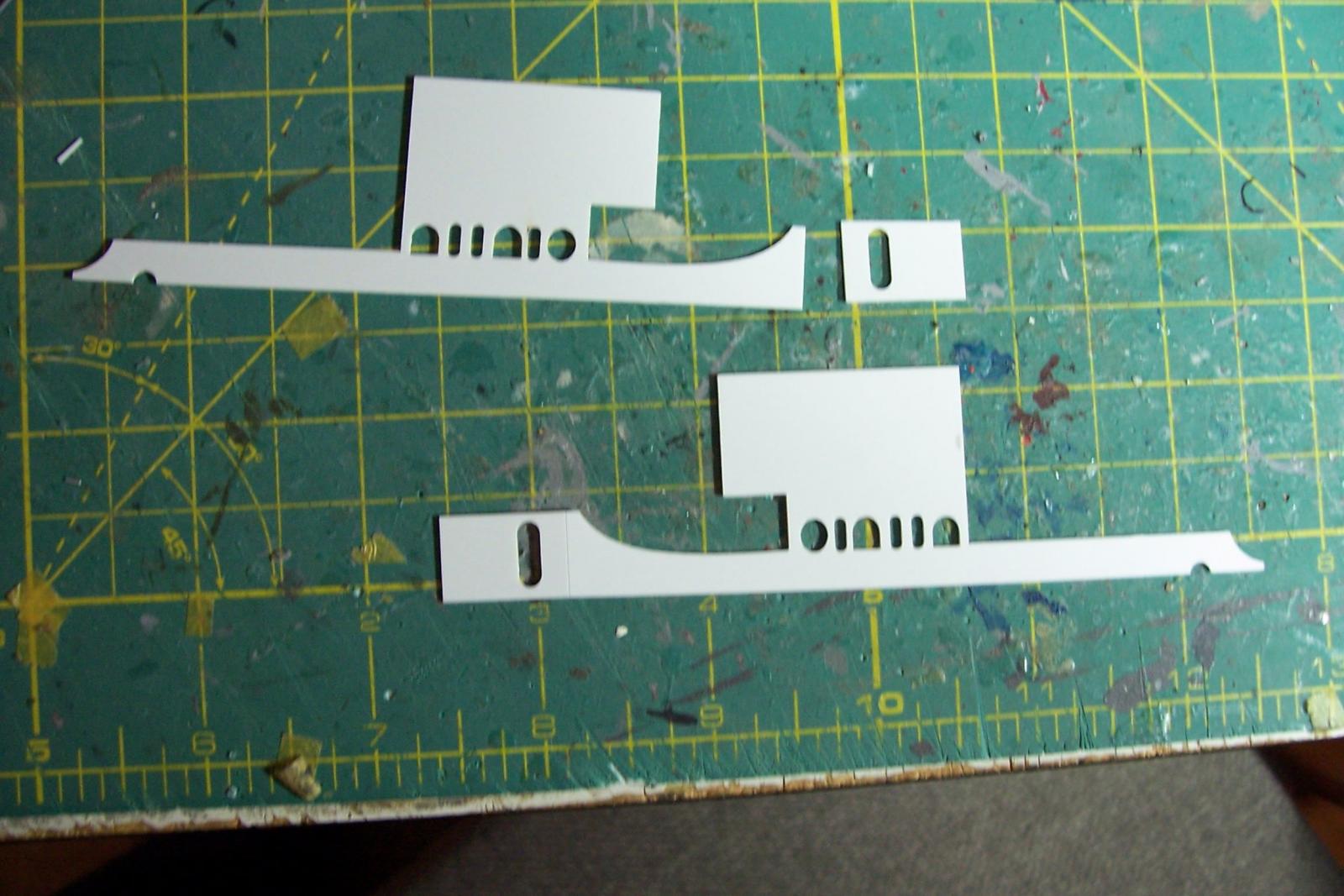
One of the distinguishing features of the Gearings was there prominent bulwarks with 6 varied openings of circles, ovals and arches. Although during the FRAM modernizations the superstructures were completely removed the bulwarks were rebuilt the same as before - one of the few points of continuity from their pre-modernization appearance.
The kit provides the bulwarks as a single piece of laser cut sheet plastic with a thin section were a bend occurs. One of mine broke at that point but it was just as well, with so many points of contact it would have been difficult to fit it without breaking it down into pieces. It also worked out OK because the door cutout was too big for the PE frame I wanted to use so I made new pieces with slightly smaller door openings.

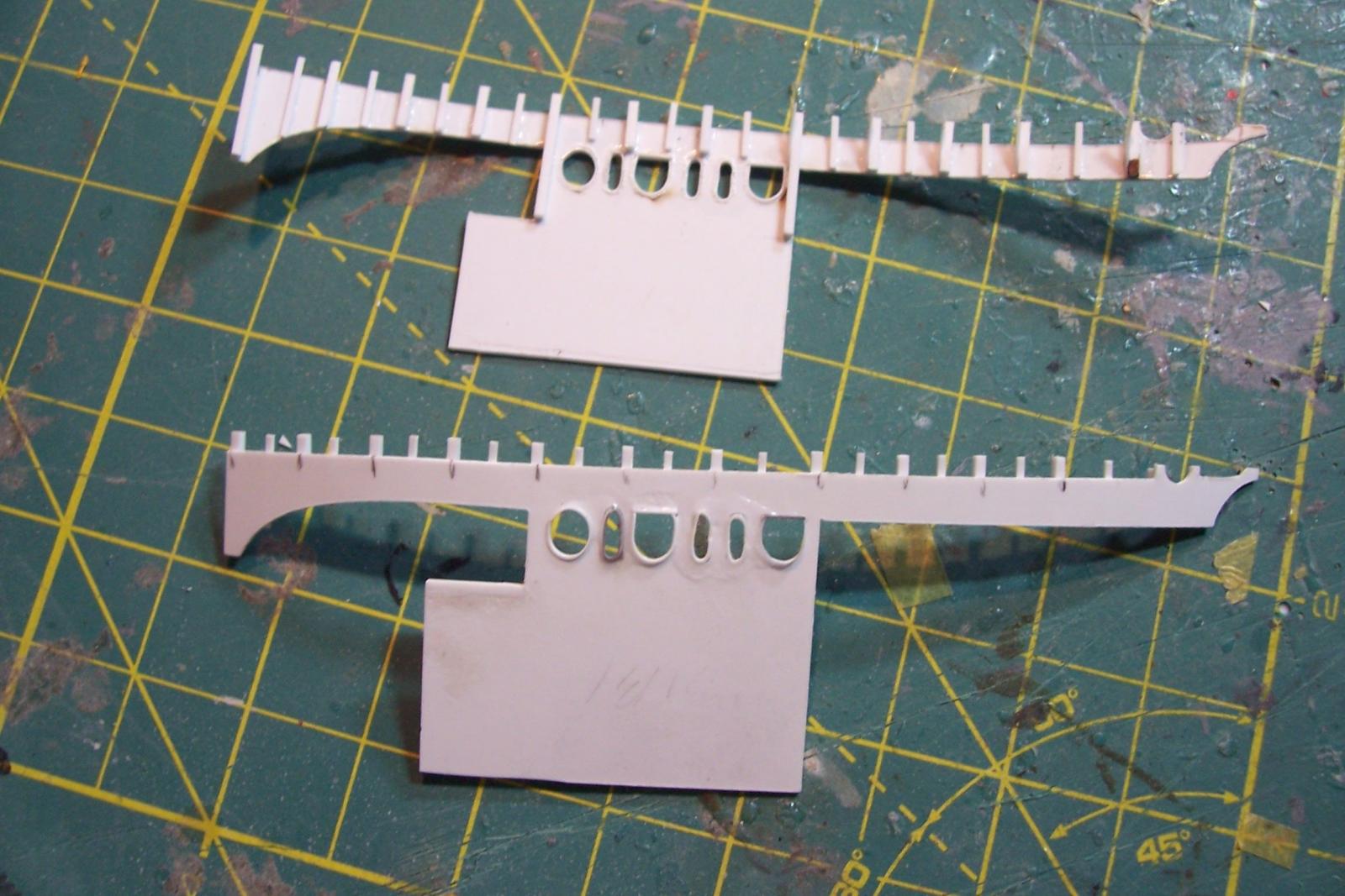
The first modification, although the kit instructions don’t mention it, the kit plans clearly show that the bottom of the bulwarks do not rest flush on the deck but are supported by the bottom of the interior stiffeners. I cut off 1/16 inch from the bottom, added stiffeners to the inside face and angle braces for the aft section (the rest would not be visible). The other modification was to line each opening with support bracing.
After painting and fitting the bulwarks I printed out the emblems for DESRON TWELVE which BASILONE was assigned to in 1966 in Newport. I got the design for the emblems from a former BASILONE sailor. This small step took an extra trip to the hobby shop since I didn’t think about the fact that printers don’t print white, so back I went to get white decal paper.

Next step will be to add the chocks and bollards to the main deck.
- justsayrow, s4usea, GuntherMT and 3 others
-
6
-
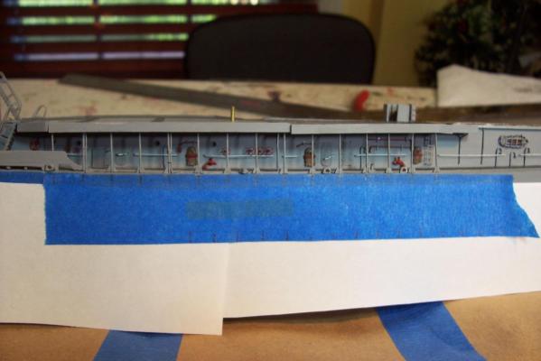
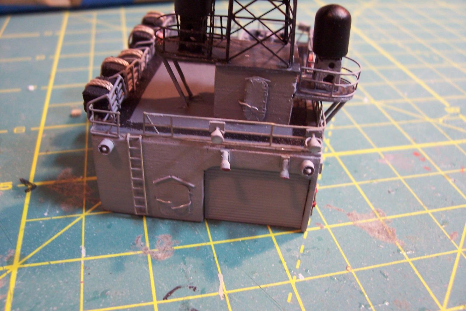
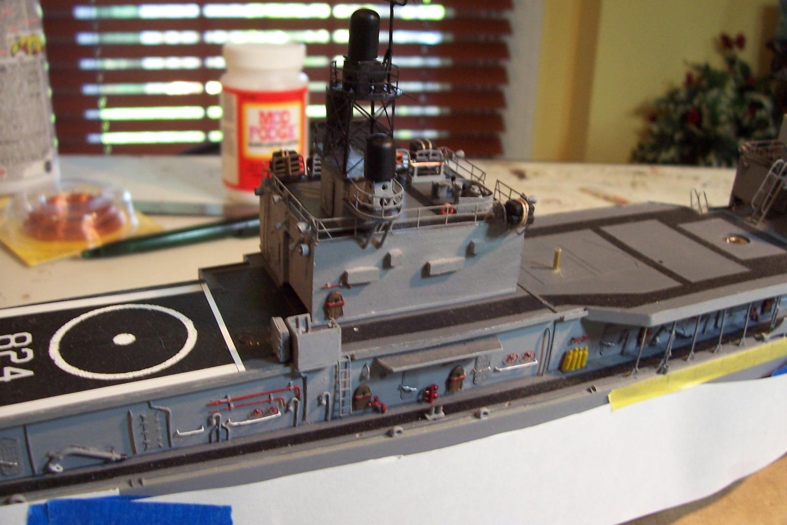
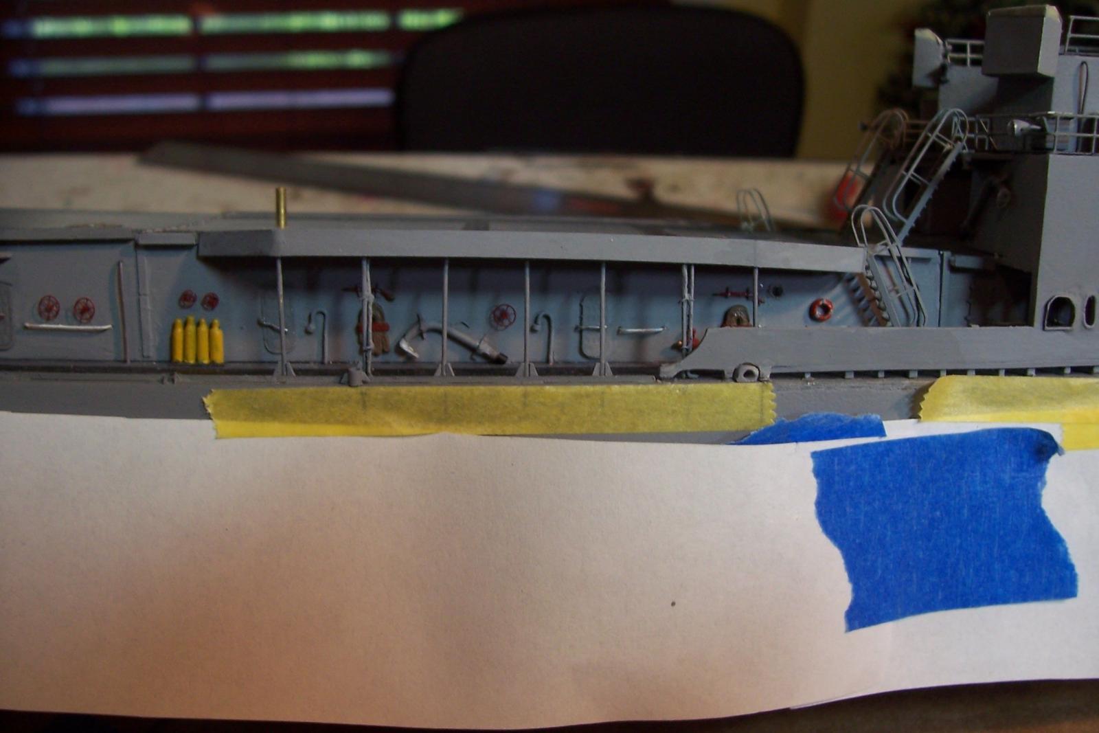
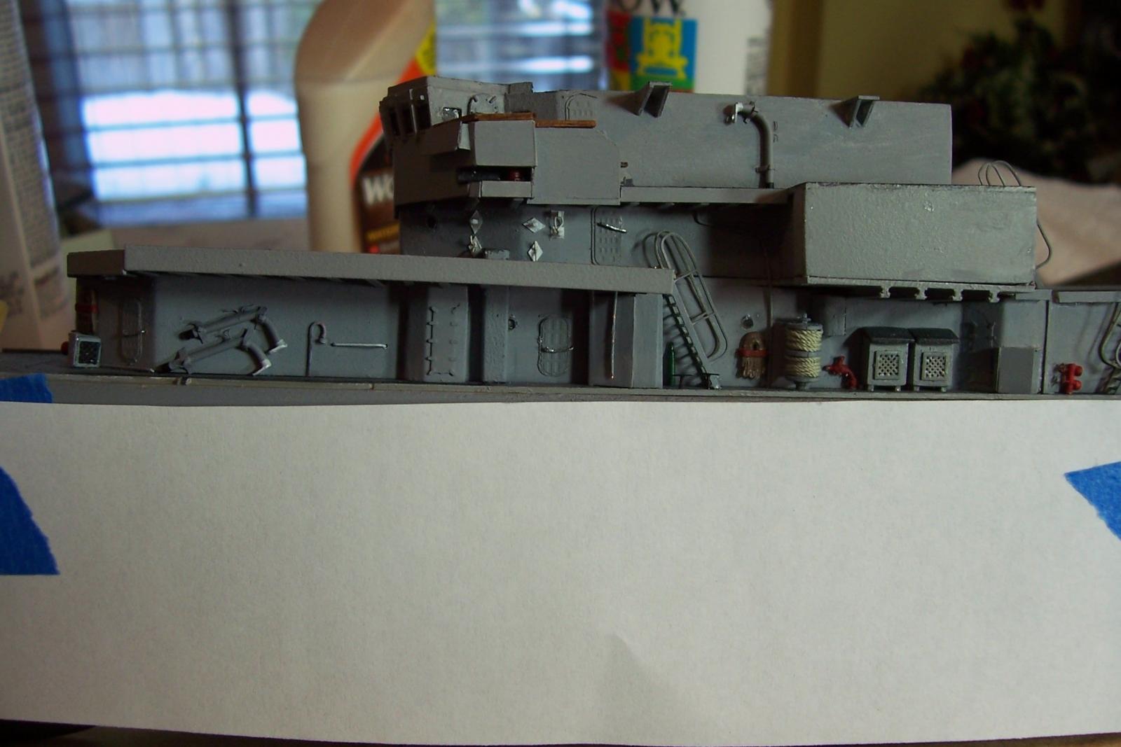
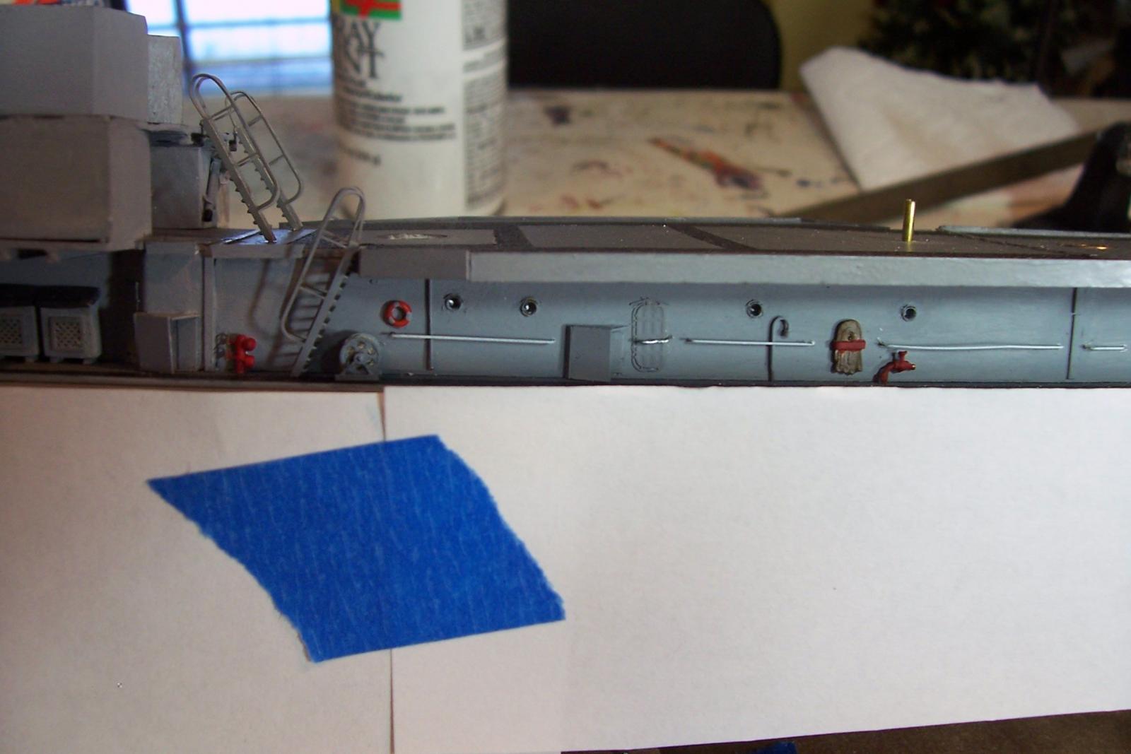
Main Deck Bulkhead details
Have been slowly adding small details to the bulkheads on the main deck level. I covered the watertight doors in a previous post.
Kit-provided additions since then include vegetable lockers. ladders, large line reel, and grab rails.
Aftermarket PE additions include the porthole rims, the hand wheels on the deck (must have been real shin breakers at night), and small line reel.
Scratch additions include deck drains, gooseneck vents for fuel tanks, water diverters, vent outlets, fog gong and locker on aft bulkhead, life rings, and oxygen bottles. Still to go are the remote operated valve hand wheels and firefighting equipment.
The ugly vertical surface with the exposed I-beam ends will be covered up with a bulwark shortly.


- hexnut, mtaylor, justsayrow and 5 others
-
8
-
Hey Steven,
I'm glad to see a build log of this kit, it has been on my radar for a while but I have not been able to find any build logs of it that went beyond the hull so I hope you make it to the finish line. Given your boatbuilding skills you should do well this this.
Good luck
Tim
-
Hey Pat,
I just came across your log. Great looking ship, can't beat an all gun destroyer. Glad to see another steel-hull build underway. I'm really looking forward to watching you detail her. I've been having fun doing that on my Basilone build but at 1/192 it's quite a bit easier than 1/350. On the other hand there are a ton of after market PE and decal options available to you at 1/350, much more than at 1/192.
I've built a few small resin kits. Pin holes and voids are just part of the fun, yours doesn't look too bad compared to other manufacturer's. Before you get to the stage of painting stuff I hope you are aware that resin parts have to be cleaned first or the paint will not stick. Some kits just need warm water and soap, others need commercial silicone remover. You may want to experiment on some scrap pieces before you go big on painting.
If you have not checked them out, L'Arsenal has a lot of 1/350 resin and PE details that might come in handy, that said the upgrade kit for your model looks really sweet so you may not need to go anywhere else.
Good luck and have fun
Tim
- popeye the sailor and Canute
-
2
-
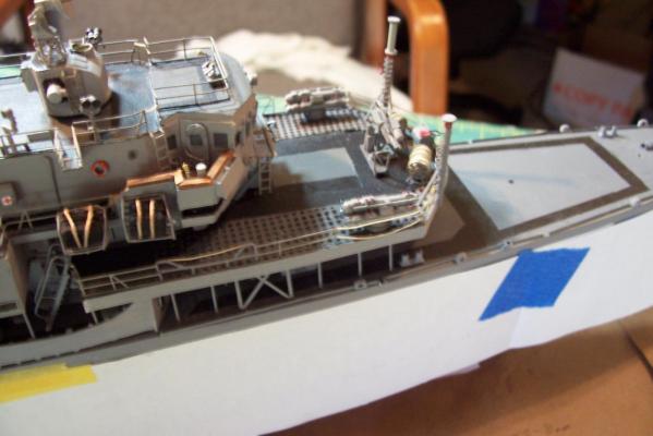
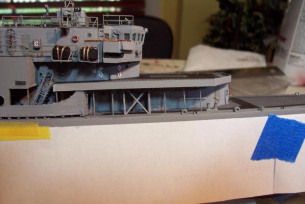
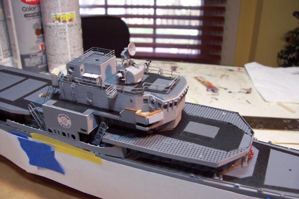
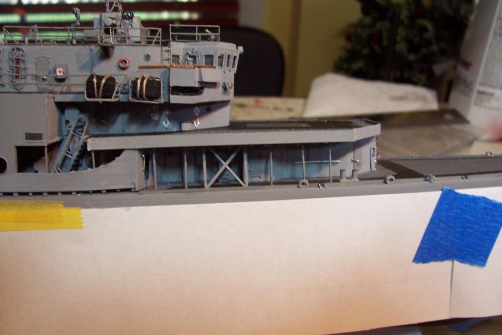
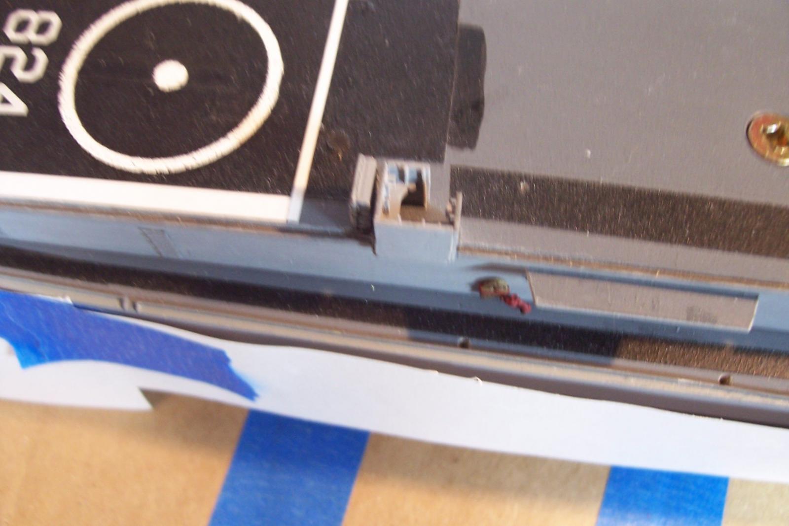
DASH Control Station
THe DASH Drone was controlled from an open air cubicle on the forward edge of the flight deck. It was basically a desk with a little protection in case the drone got too close. All the control electronics were in portable suitcases so the station was minimally equiped.
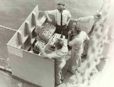
Here’s what I came up with (the cable cabinet is scratched based on photos):

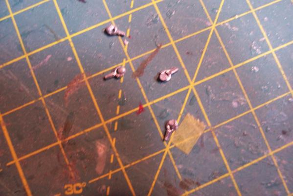
Portable J-davits
Simple davits were stored around the weather decks and used for such things as rigging the accommodation ladder and lifting heavy objects from boats alongside, between decks and even up through the large foclse and fantail hatches:
I scratched some out of wire, styrene and paper for the mounting brackets.

When not in use they were usually stowed in brackets on a bulkhead:
-
As far as positioning the letters on the transom, something that worked well for me in a similar situation is to type the ship's name into a word processing program, change the lettering style to something close to the PE letters, adjust the font size to match them, and then with a little trial and error adjust the letter spacing, cutting out the name and fitting it on the model each time until you get what you want. When you have it the way you want it trim the paper name close to the top of the letters and tape it right under where you will place the letters. It will act as a guide in getting them where you want them. Some word processing programs will let you bend the name to match any arching on the model, if you can't do that just cut slits between the letters so you can bend the strip as needed.


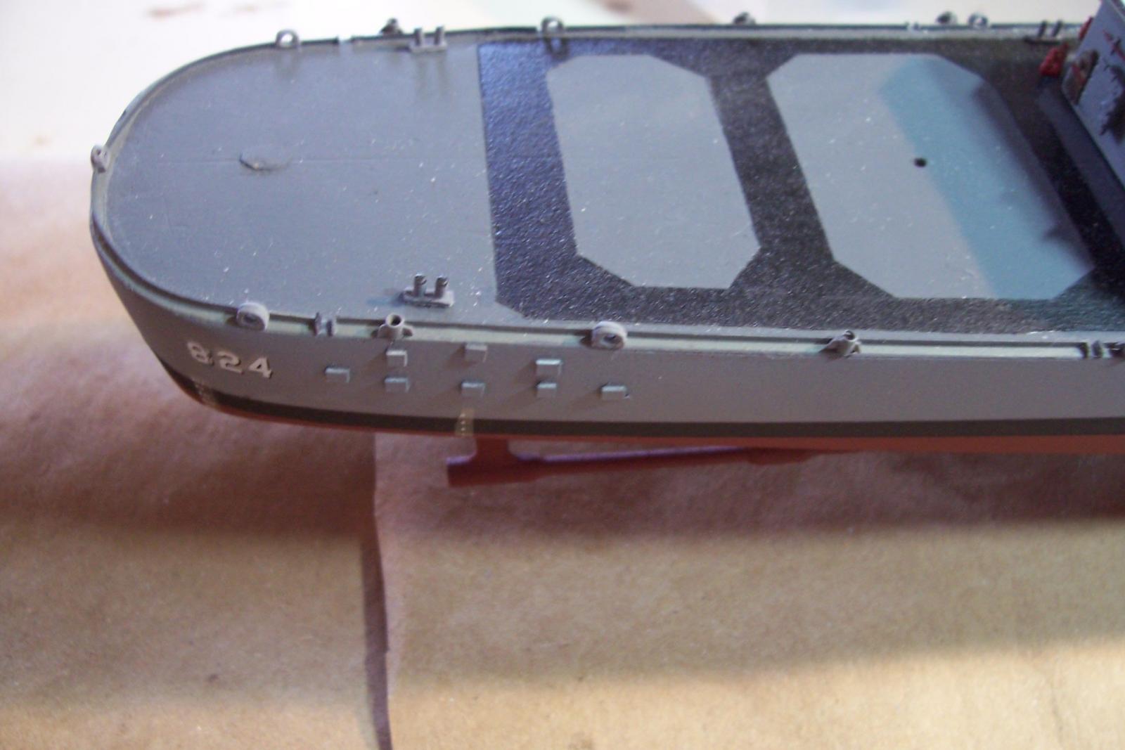


USS Basilone DD-824 by schooner - FINISHED - BlueJacket Shipcrafters - Scale 1:192 - from USS Gearing kit
in - Kit build logs for subjects built from 1901 - Present Day
Posted · Edited by schooner
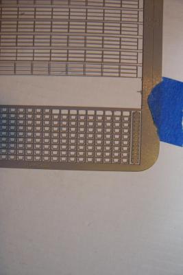
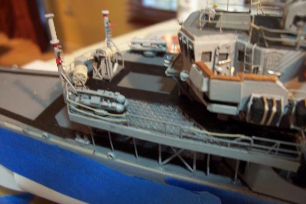
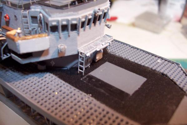
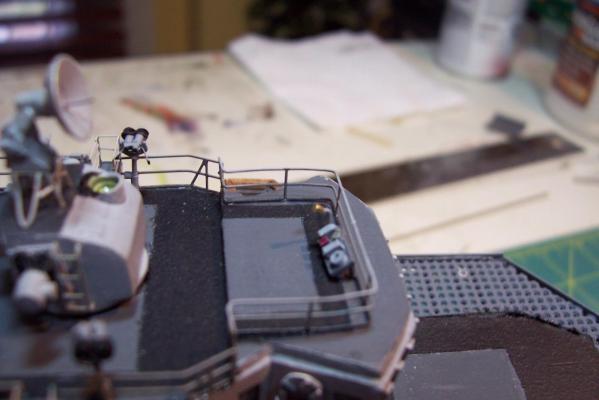
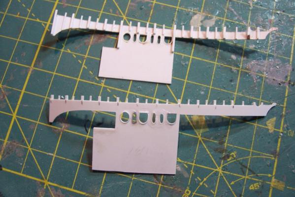
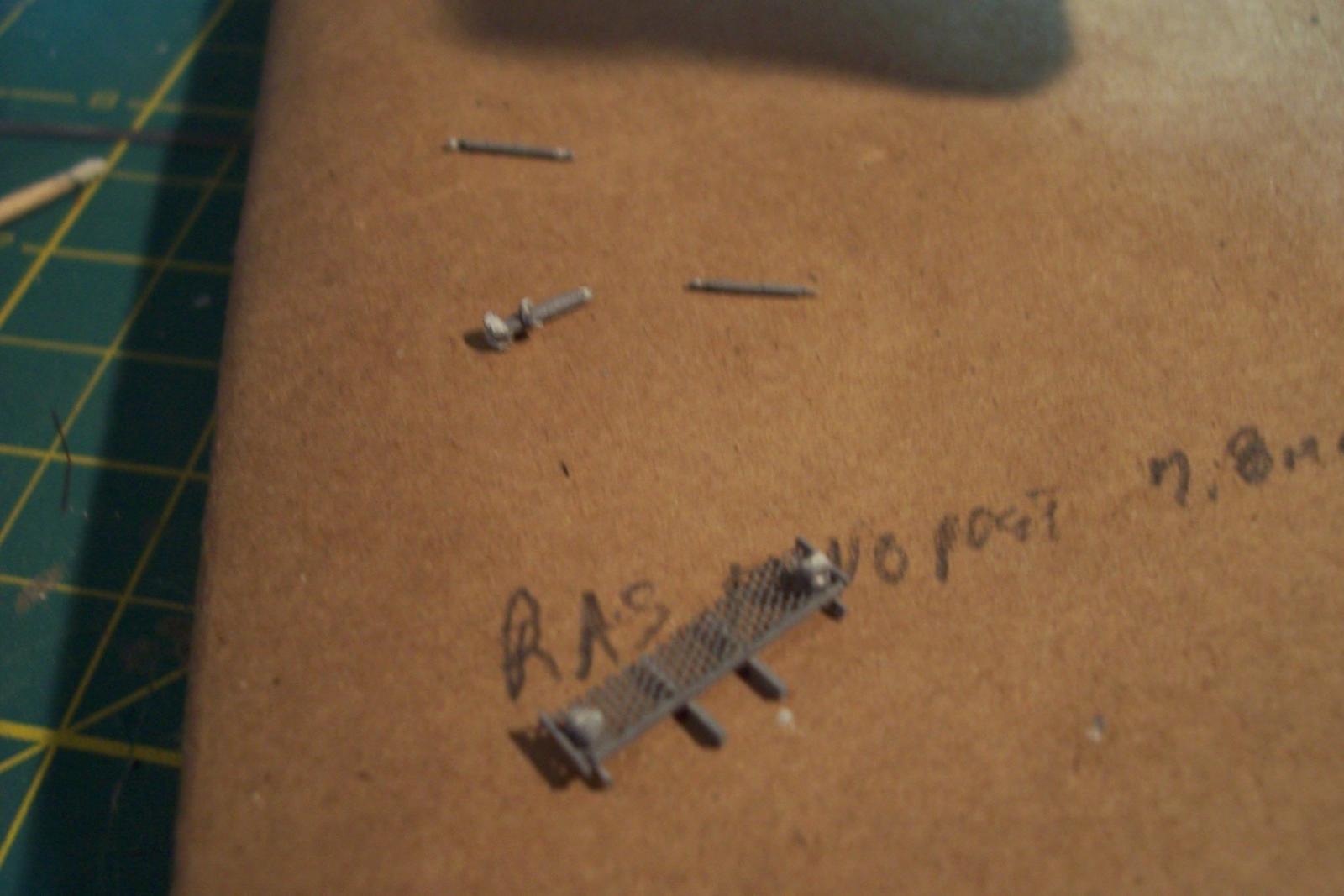
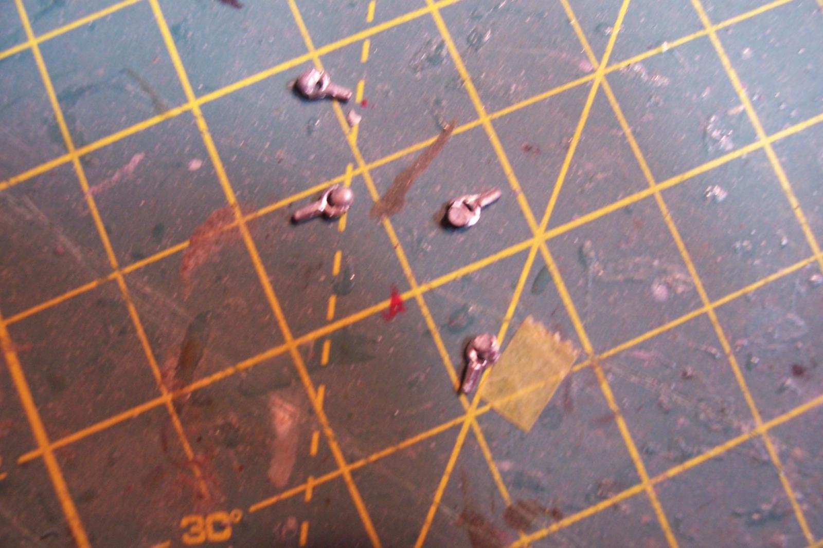
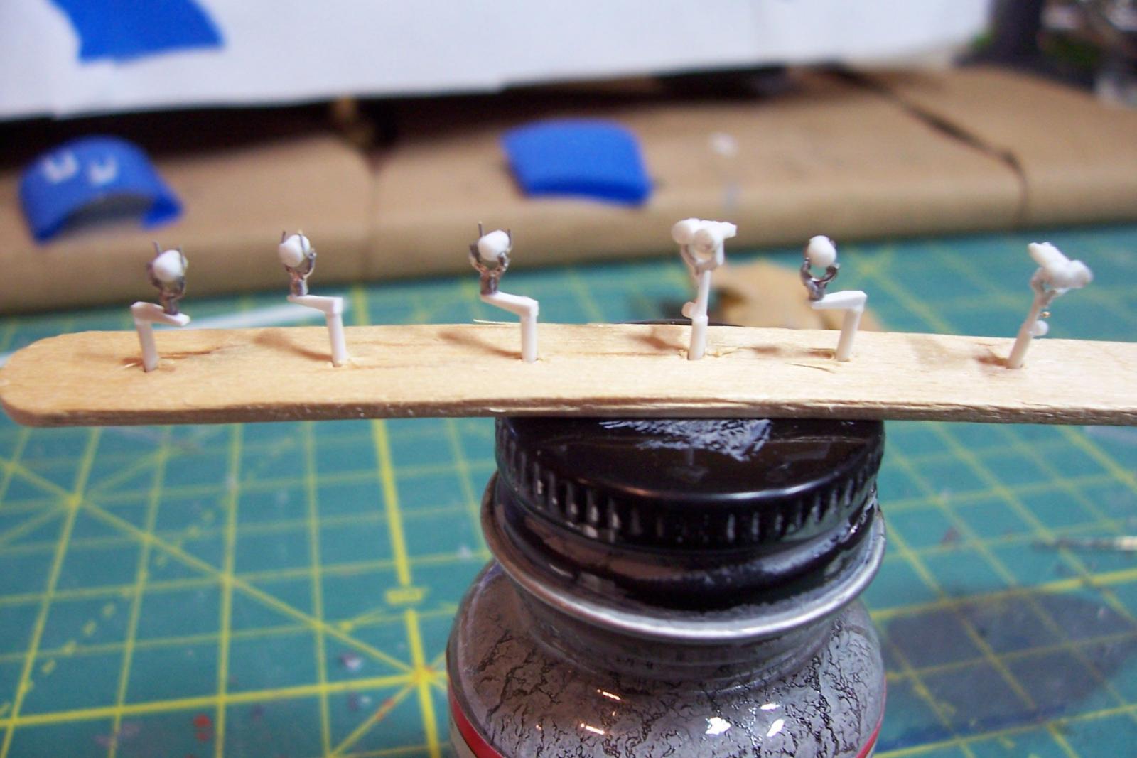
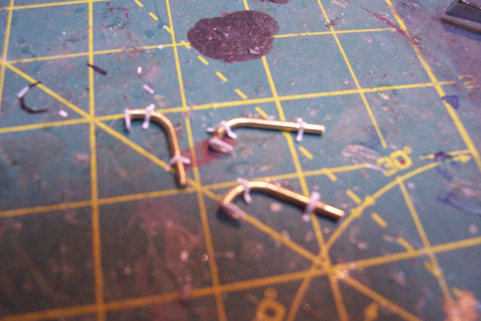
Flight Deck Nets
The kit provides some nice PE safety nets for the sides of the flight deck (they were not added to the aft part of the flight deck until several years after the time I am depicting). The instructions call for installing them in the raised (vertical) position but since I will show the DASH on the deck I chose to mount them in the lowered (horizontal) position, which would require some modifications. Since PE is inherently thin if viewed side-on the PE would appear under-scale for thickness. I decided to line the PE nets with brass wire to give them more depth:
But after making the wire frame I thought I might try adding my own netting using some fine plastic netting from the craft store (I think it is intended for floral arrangements). As you can see from the attached photo the netting should be very fine, almost invisible.
Here’s my first attempt after spray painting (2nd from the top below) - not too good, the paint made a mess of the netting. Next I tried adding the netting after spray painting the frames (the 3rd from the top in the photo below), better but the frames still looked bad so I threw out the spray paint, painted the frames by hand and then added the netting (bottom one in the below photo) - much better. The craft store mesh is to scale and as an added bonus the openings are diamond-shaped, just like the real things!
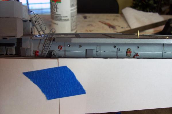
After making and installing the nets I wanted to add the “guy wires” (for lack of a better term) that support the nets in the lowered position. I decided to drill a hole in some small strip plastic and insert a piece of 3X fly fishing leader material, cut off the small piece of strip stock, paint it and install it. Here it is being assembled and after installation prior to trimming:
Here’s the finished product:
Next step will be the whaleboat and davits.