

schooner
-
Posts
642 -
Joined
-
Last visited
Content Type
Profiles
Forums
Gallery
Events
Posts posted by schooner
-
-
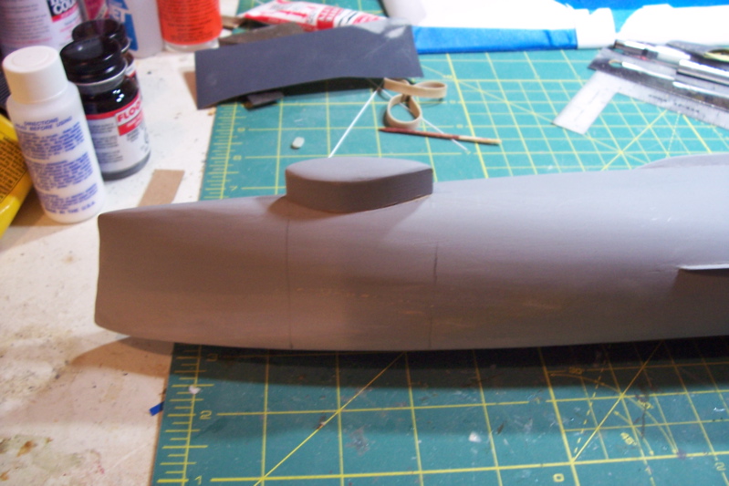
Sonar Dome
This is an easy part – adding the sonar dome.
The Basilone carried an SQS-23 sonar which was a big improvement for its time. It was the first sonar with a rubber window in the dome and was supposed to be able to bounce active transmissions off the ocean bottom, although conditions for that to be able to work were very rare. When I served on ships with later, more powerful sonars we called to the SQS-23 the “Helen Keller sonar” although to be honest, compared to submarine sonars ours wasn’t much better.
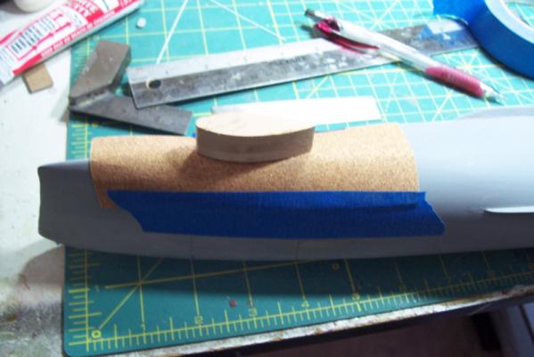
The dome comes in 3 laser cut parts, the hollow piece goes against the hull. It’s hollow to reduce the amount of surface area that must be sanded to conform to the hull.

After stacking them and gluing them together they are placed on a piece of sandpaper taped over the hull where the dome will fit and its easy to sand it to fit.
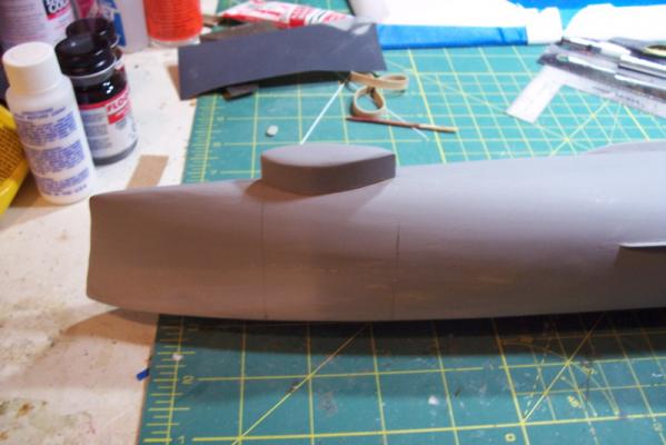
After that the dome bottom is rounded and then it is glued to the hull. When the hull underbody is painted red later most of the dome will be painted black to simulate the rubber window.
Now that this is done I can remove the vise block, turn the hull right side up, attach it to a building board and start working on things that are not almost "out of sight - out of mind" like all this underwater stuff is.
That’s enough for now – time to go see if the trout are biting.
- hexnut, Captain Slog, Script and 1 other
-
 4
4
-
Thanks Patrick and Scott for the kind words.
Patrick – if you like that poster there are a million more at www.despair.com
Having spent too much time in offices and conference rooms where those “motivational” posters abound, finding that website helped me suppress the gag reflex everytime I saw one.
-
Hi Patrick,
I wouldn't call it a practicum but if it helps anyone, even to avoid my mistakes, then it's worth it

- justsayrow and JPett
-
2
-
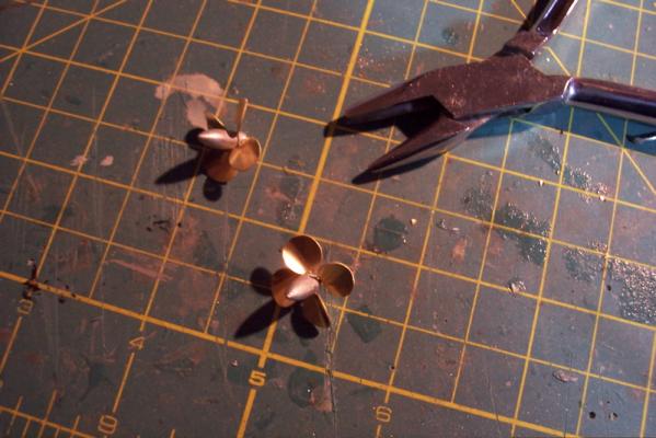
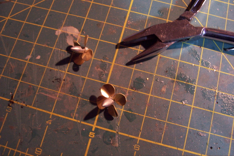
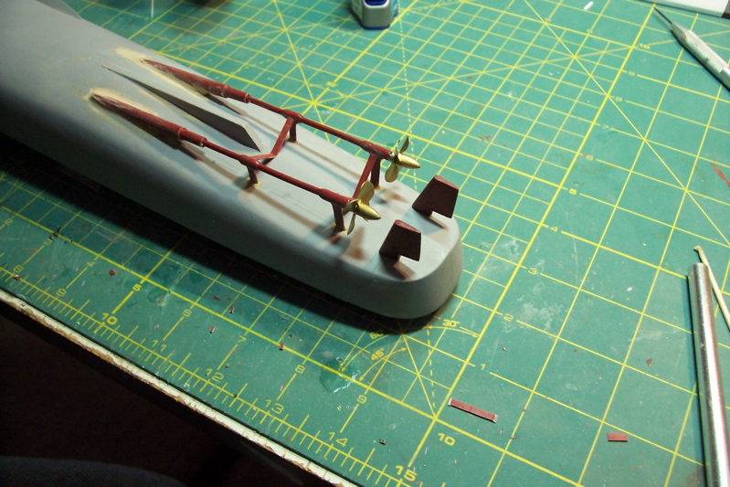
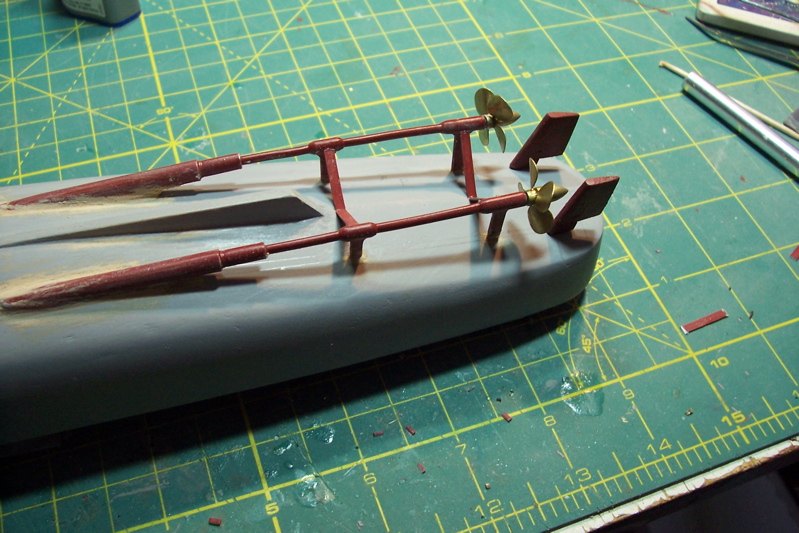
PROPS AND STRUTS
The prop blades are made up of PE brass, the hubs, collars struts and shaft bosses are cast Britannia.
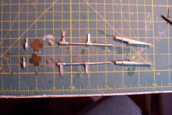
The instructions call for making the props quite a ways further down the road but I’m doing them now to prevent a potential problem that I will explain in a bit. The prop parts fit together well. Twisting the blades to provide a right and left hand prop is easy enough but giving the blades the proper pitch (curl) is a little more tricky. Fortunately I have a set of four metal forming pliers that I got from Micro-Mark, one of which made this step easy.
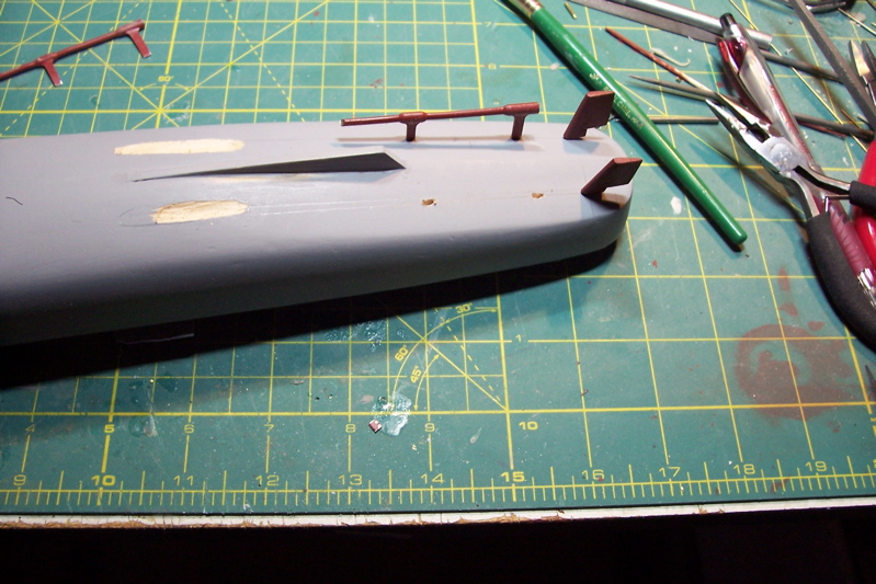
After marking the axis’ of the shafts, checking them against the rudder post locations, and marking the locations for the struts slots are cut for each strut.
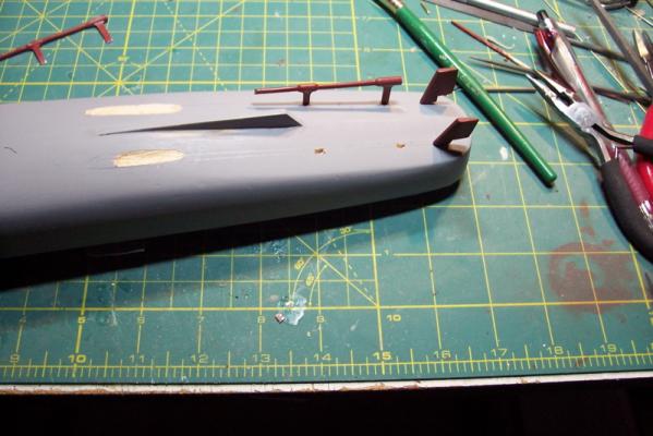
The shaft bosses (the shaft tube where it penetrates the hull) now have to be fitted so that they mate with the shafts, keep the shafts at the right angle, and most importantly – maintain their axis parallel with the axis of the struts so there are no “bends” in the shafts. By a combination of filing on the boss bases and getting them lower to the hull by removing some wood below them everything finally lines up.

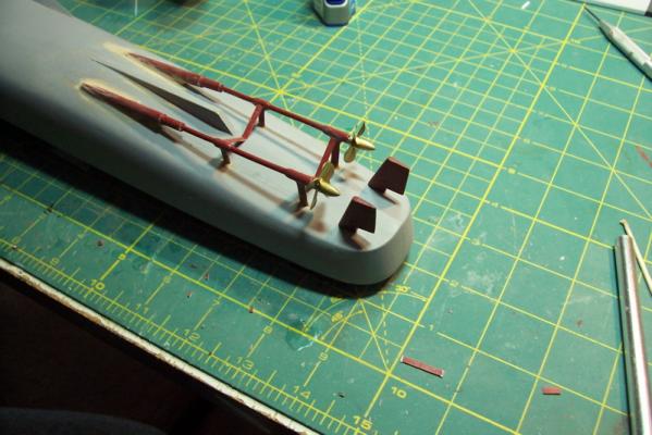
When planning this section I had to stop and think “How can I possibly screw this up?” The worst scenario would be to get ready to add the props right at the end of the whole build and find they didn’t fit – that’s why I made them up now. The final check before everything is glued in place is to dry fit everything to make sure that the screws have adequate clearance longitudinally to the rudders and vertically to the hull.
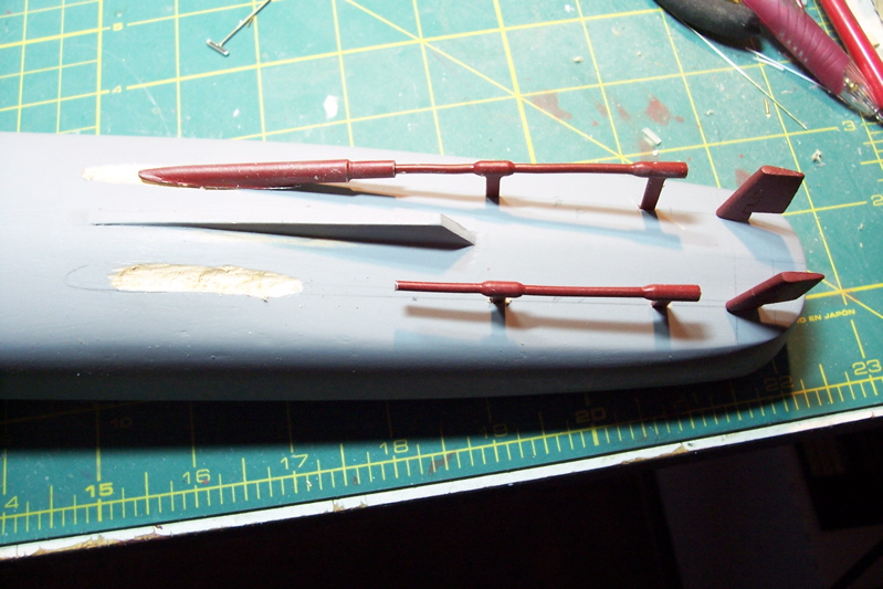
After gluing the bosses and shafts in place strip plastic is cut to size to make up the inner shaft struts. I gave everything a preliminary coat of red so that when I get around to spraying the hull underbody I won’t have to try to reach the back sides of this stuff.
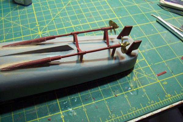
The props will be removed and stored in a safe place until they are added just prior to casing the model. They are very fragile and would be easy to damage during the build if left on the model.
Next up will be building the sonar dome.
-
Thanks Patrick, I appreciate the compliments.
-
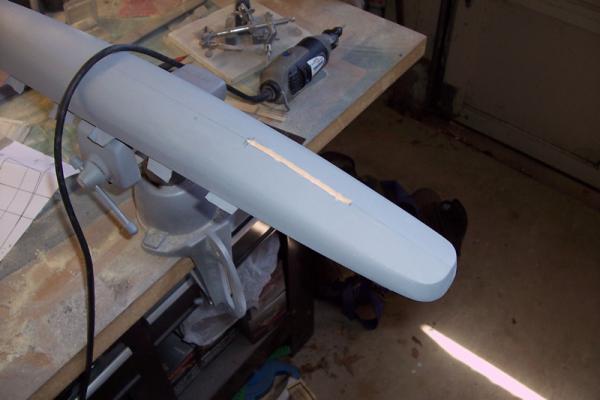
ADDING THE BILGE KEELS
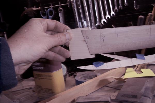
The bilge keels’ location is marked on the hull and a 1/16” wide by 1/16” deep slot is carved using a hobby knife and a file.
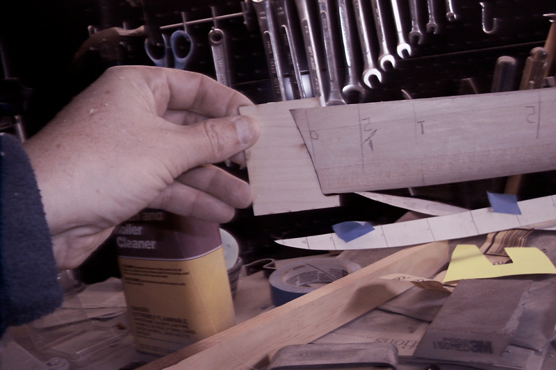
The keels themselves are fabricated from stripwood, tapered at each end and sanded to a knifedge on the outer edge. After a lot of adjustments the keels fit into their slots. The bilge keels’ function is to help reduce rolling in a beam sea and provide stability during turns.
Next up will be fitting the struts and, temporarily, the props
- Captain Slog, hexnut, justsayrow and 1 other
-
4
-
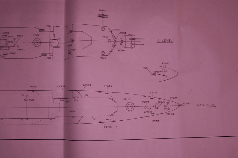
Took a break earlier this week to go out to the National Archives facility in College Park, MD in order to look at the plans for the Basilone. It was well worth the trip because the Basilone had several differences from the Gearing and the plans at the NA are more detailed than what I got from the Floating Drydock.
Anyone who is thinking of building a model of a post-1880 USN ship and lives within comfortable driving distance of Washington DC may want to think about taking a trip out there. They do have more rules and procedures than the TSA but they are all laid out on their website – as long as you know what to expect it’s no big hassle. They do have a search function on their website that will tell you what they have available on your ship.
Another modeler who built this kit ordered the plans from the NA but the cost was several hundred dollars. If you go there they will print them out for you on paper there but it is still $3.50 per linear foot, given that each sheet of plans is about 5 ft long that is still pretty pricey. They will digitize the plans on a CD for you for about $3 per sheet. Since I only needed 4 that was about $11. I then took the CD to a local blueprint service who printed them out for me for $10. So for about 20 bucks I now have clear, detailed plans to support my build.
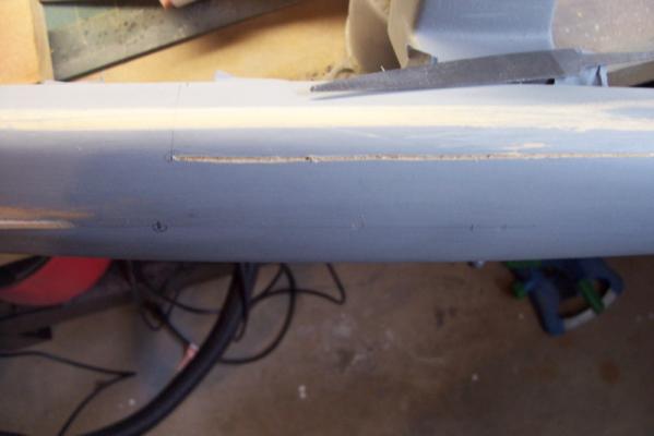
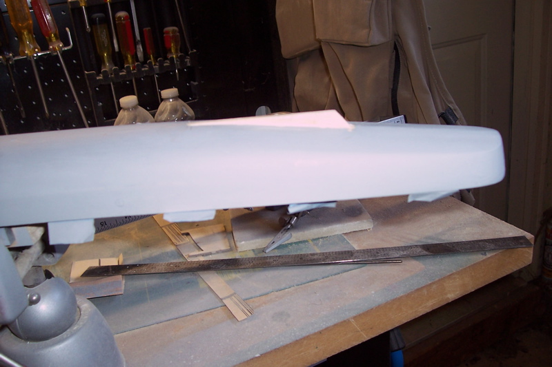
ADDING THE SKEG AND RUDDERS
After shaping the hull I finally was able to stop doing subtraction and begin to do addition.
The first thing to add was the skeg. After marking the location on the hull, some burr head fittings in my Dremel made quick work of excavating a trench for the skeg to sit in.
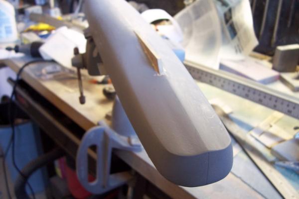
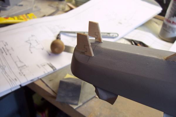
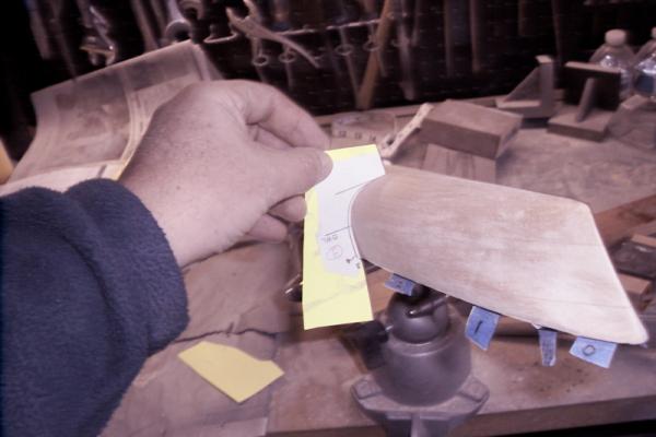
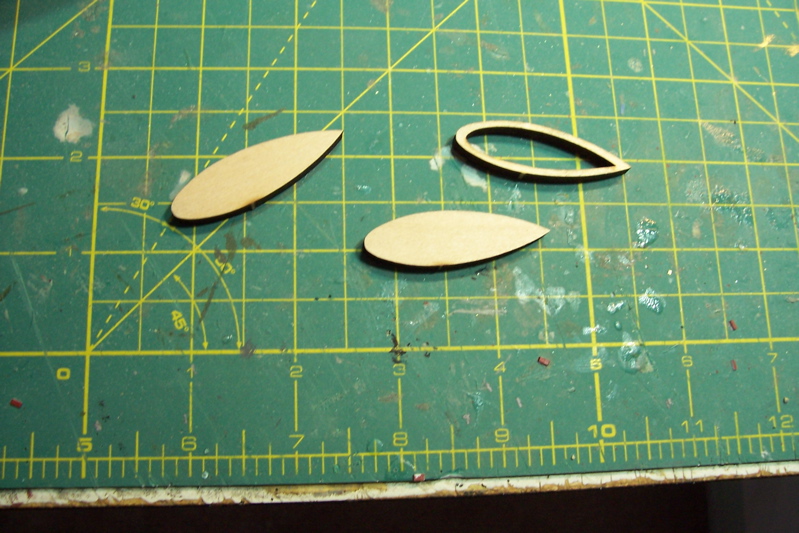
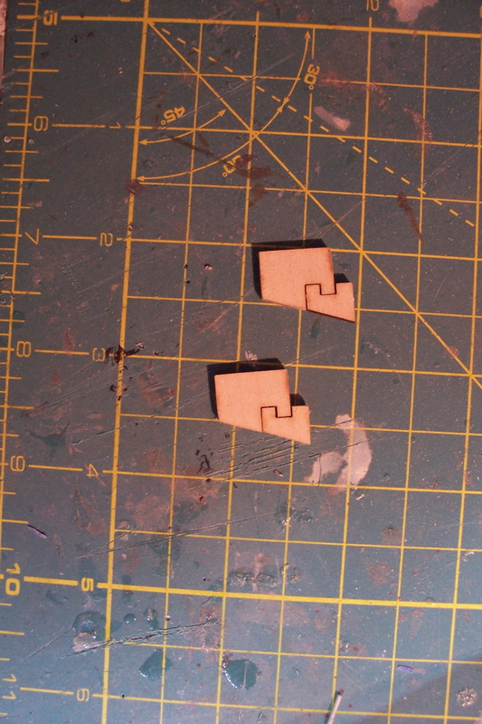
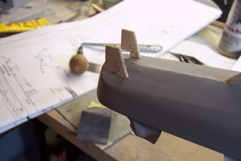
The rudders are made up of 2 pieces of laser cut wood. After joining them they are sanded to an airfoil shape.
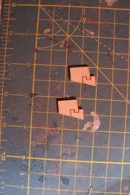
The joint between them should be maintained and not filled in or covered with too much paint because it represents the junction between the fixed and moving parts of the rudder and is visually prominent.
I dry fit the rudders to the hull to use as a reference point for placing the propeller shafts.
Next step will be fitting the bilge keels.
-
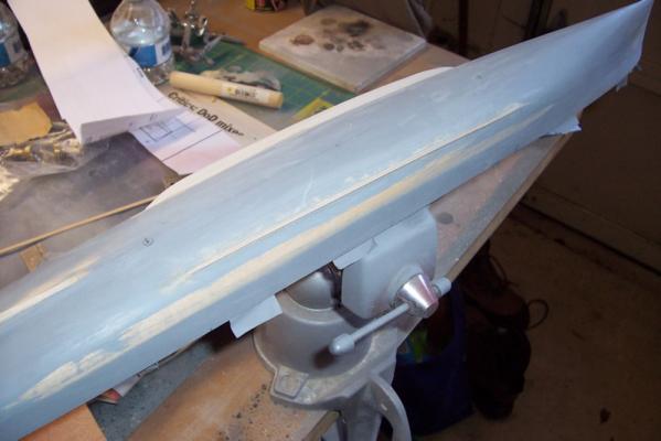
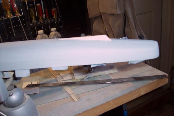
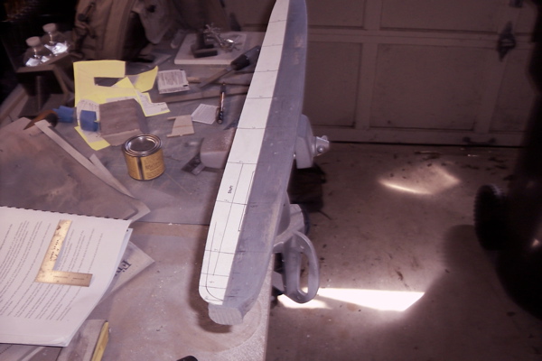
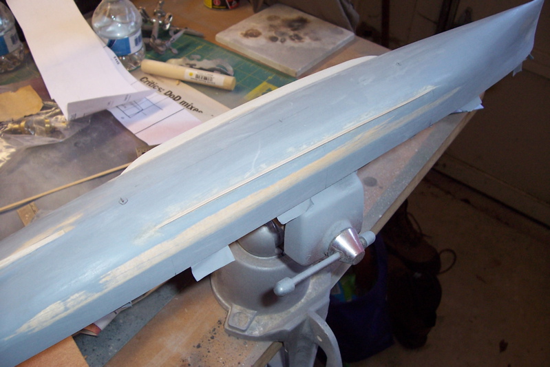
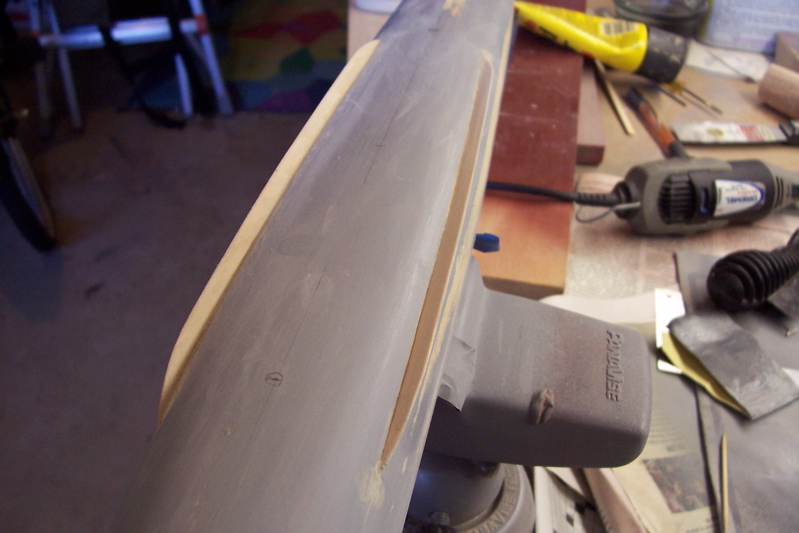
SHAPING THE HULL
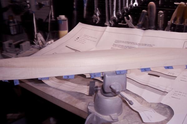
Shaping the hull using mainly sandpaper and occasionally files, and very occasionally a Dremel is for me the most tedious part of the build.
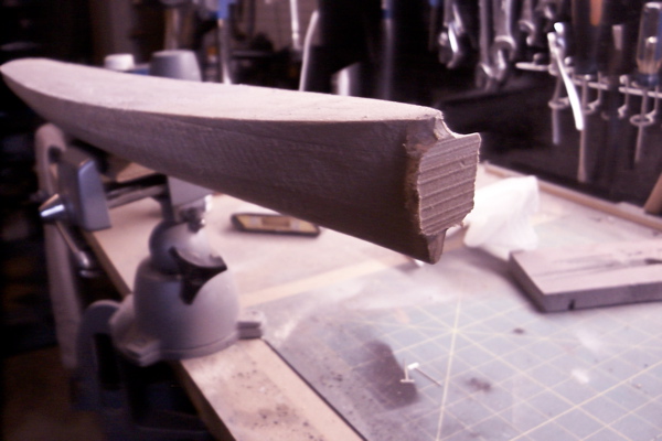
Having removed the machining plugs on the bow and stern and marked the hull with the template stations, the hull is now ready for shaping.
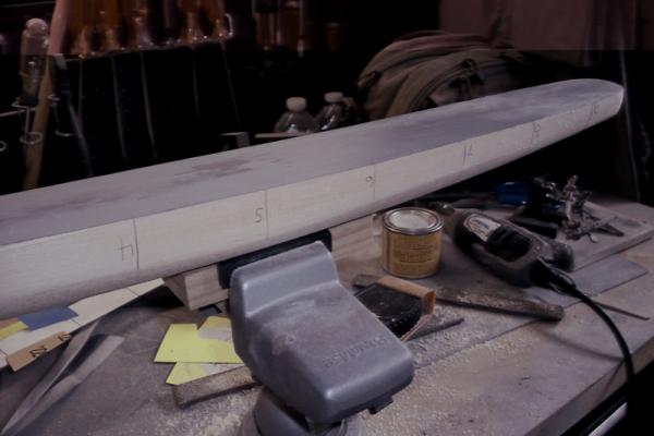
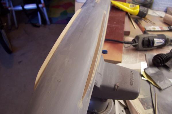
I started out by bring the bow into its proper profile, as viewed from the side, mainly using files, and verified by a laser-cut template provide in the kit. The gap at the bottom of the template is not a problem, the same gap appears when the template is layed on the plans so the height of the bow is OK.
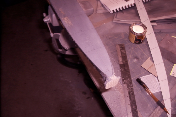
After that I started working my way aft checking 2 or 3 stations at a time to see where the wood needed to be removed and then sand, sand and sand some more. If you have never worked on a solid hull my recommendations are:
- Always use a sanding block, freehand doesn’t give you the control you need and it’s really tough on your hands
- Use long strokes in a fore and aft direction, that will help keep the hull lines fair between the stations
- Alternate your sanding on the port and stbd sides, don’t try to do one side then the other
- Be careful near the deck edge, you want to keep a sharp edge (another reason for using a sanding block)
- Avoid power tools except where you can easily tell what needs to be removed, in this case I only used a Dremel to remove the machining plugs. Power tools can quickly remove too much material and lead to an uneven, wavy surface. Also resist the temptation to use sandpaper any rougher than about 100 or 110, sure it will go faster but it may go too fast, and ending up taking off more than you want
- Keep checking your progress using the templates, check both sides and 1 or 2 stations “further down the line” in the direction you are working. The hull doesn’t make any radical changes in shape between stations so you need to keep cognizant of how it will change as you progress
- If you need to impart a curved surface into the hull, like I did to give the bow some flair, and some slight concave areas above the screws, then wrapping the sandpaper around a round object of the appropriate radius will do the trick.
- Take your time. I find this kind of work mind-numbing so I only do it for 10 or 15 minutes at a time or I get sloppy
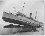
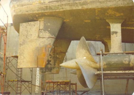
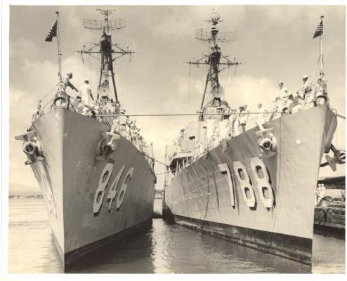
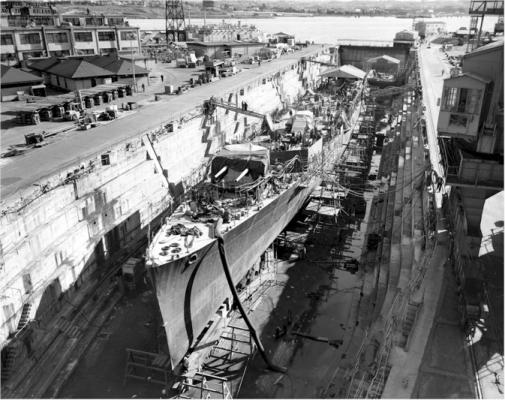
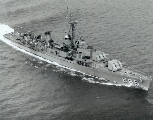
Since the furthest forward template station is a few scale feet aft bow, there is no indication on the plans of just how narrow the cutwater should be. I found some photos online, like the one below, that indicated the bow was rounded right under the forward-most enclosed chock (the “Bullnose”) but then narrowed to a knife edge just 2 or so feet below
A few words about the wood, I'm 99% sure it is Basswood. It sands easily but keeps a sharp edge where needed, it doesn't produce any "fuzz" so I didn't need to use any sanding sealer or wood hardener and it seems free of any oil so it takes spray primer well.
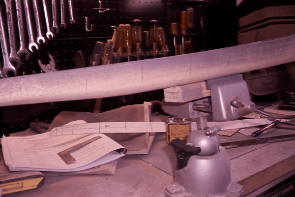
After about 5 hours of sanding spread over 3 days the hull is now in its final shape. Next step will be to give it a fine sanding using 400 grit sandpaper, then prime it to highlight any rough or uneven spots, sand or apply filler as needed and then repeat the whole process until the hull looks like metal rather than wood.
- hexnut, JPett, justsayrow and 4 others
-
7
-
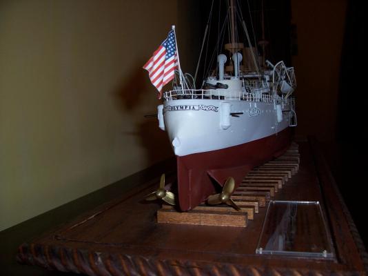
Thanks Bob, hopefully this one won't take me near as long to build as the Olympia did, but then again, that one was before I took up fly fishing so it could be even longer.
-
Thanks Patrick, glad to have you aboard.
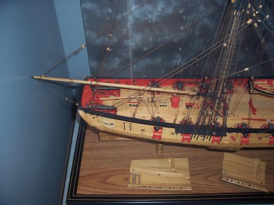
Congratulations on your Niagara, she is the best I've seen. You did a spectacular job on the woodwork, painting and rigging - first class all around!
The Niagara kit is one I've been mulling over for a long time, seeing what you have done with it may push me over the edge.
If you haven't already, you might enjoy looking up the history of what O.H. Perry had to do to build the Niagara and the rest of his squadron. It's amazing what they were able to accomplish in such a short time, given that every nail, rope, cannon (and flag) had to be dragged across hundreds of miles of roadless wilderness. It was just as hard, if not worse, for the Brits on the other side of the lake. Of course the price paid for building with green wood in a hurry was that all of the ships were rotted wrecks within 2 or 3 years of the battle, but they had served their purpose by that point.
-
PREPARING THE HULL FOR SANDING AND SHAPING
The instruction books starts off with a cautionary note that due to varying manufacturing and environmental conditions the plans may differ in size from the Mylar masters they were made from. Several reference measurements from the bow to key items like the gun mounts and the front of the superstructure are provided in case there is some discrepancy. The length of the hull on the plans should be 24 7/16”. My plans measured out only 1/32” over. Since that is well within my personal margin of error resulting from clumsy fingers, aging eyes and poor technique I think I am good to go.
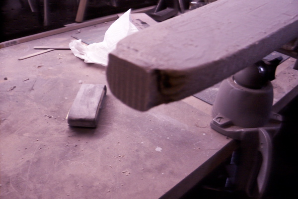
After mounting a temporary vise block to the keel, the hull is ready to mark up. The next 2 photos show the machining plugs on the bow and stern that will have to be removed.
Once the deck has been sanded smooth the centerline is measured and marked.
Using the centerline as a guide, the deck template is laid along it and the outline of the deck edges are marked and the locations (stations) for checking the hull shape using templates. (Sorry but the pencil marks don’t show up very well on deck against the dark grey primer I used to check for rough spots). I told you earlier that the rough hull comes out of the box very close to its’ final dimensions. Using the deck profile template as a guide it looks as if no more than 1/16” will have to be removed from some areas of the sides, in some areas virtually none will have to come off.
Finally the hull template station marks are extended down the sides of the hull. As the hull is shaped they will be sanded off and will have to be reapplied several times.
Now the hull is ready for shaping. The bow and stern plugs will be removed first, then the sides will be sanded to match the deck edge profile. After that is done the vise block will be unscrewed from the keel, the hull inverted and the vice block attached to the deck. The shaping of the hull will continue using the templates.
-
Nick and S.os,
Thanks for the replies. I thought this would be a good subject for a build log since there are few "metal" ships included or solid - hull kits. The main reason I'm doing the log is to help keep myself on task since it will be very easy to be distracted as the trout streams around here start to warm up.
Tim
-
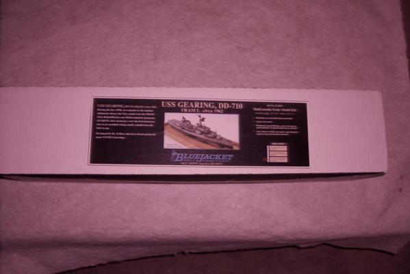
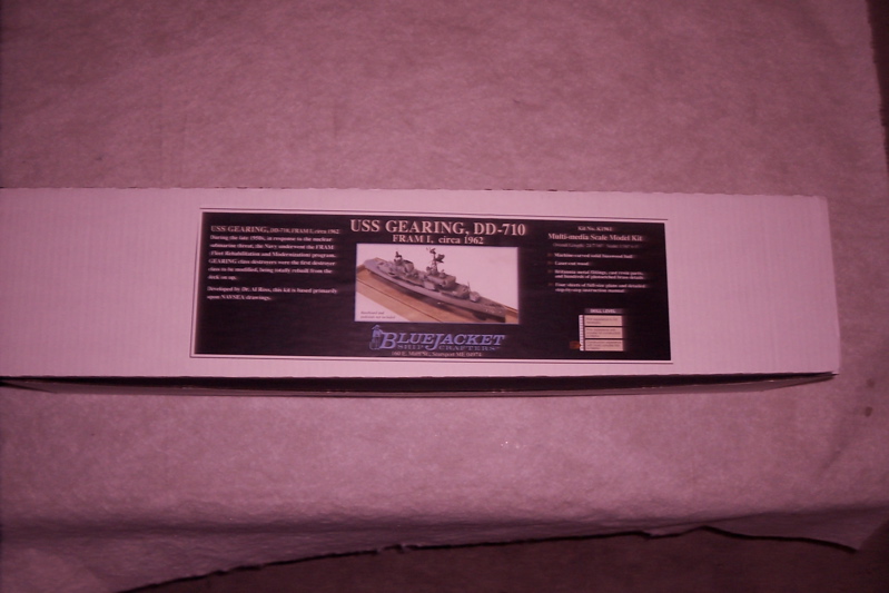
OK, here’s a quick look at what comes in the big box from Bluejacket:
Building Manual:
- The manual is about 70 pages long, has plenty of line illustrations and some photos to help explain the steps laid out in the text.
- This is probably a good place to discuss the model’s complexity. Bluejacket has a 9-level grading system to help potential customers figure out if a particular kit is within their skills. They rate this kit as an 8 out of 9 and, as they state in their catalog, “This kit is recommended for very experienced model builders.” Having built two of their previous kits I can vouch for the accuracy of their rating system. This is not a kit for a first-time model builder. Although none of the steps look to be as hard as planking a POB hull, it is still a complex model. The instructions tell you WHAT to do, but not always HOW to do it, which is appropriate for a kit intended for experienced builders. Both Bluejacket and Model Shipways have some great starter kits. One or two of those and maybe a Bluejacket kit that they rate as a 5 or 6 and you should have the skills for this one. You can always call the folks at Bluejacket and discuss what would be best for you, they are all very helpful up there.
- The manual contains a complete parts listing, which should be checked against the kit’s contents upon receipt (mine had everything), and a list of recommended tools (nothing most modelers wouldn’t have on hand already)
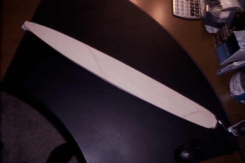
The hull

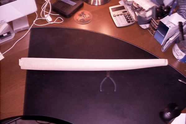
- This is a solid hull kit. If you have not done one before the idea of doing one can be a little intimidating. They are not really any harder than a planked hull … just different.
-
After building a couple of POB models I made the jump to solid hulls with Bluejacket’s USS Samuel B. Roberts (DE-413) kit. Same scale as this one. It proved to be a good choice because, just like the Gearings, the DE’s have pretty simple hull shapes. Compared to sailing ships, fishing boats and many merchant ships US destroyer hulls are basically slab-sided, have no tumble home, simple curved sterns and the bows have straight cutwaters and little flair.
- With this kit at least you will not have to carve a block of wood. What you get is a hull that is either at, or very close to, its final dimensions and with the basic shapes in place. It can be considered 90-95% complete out of the box. There are plugs on the bow and stern left over from the machining process but they are easily filed off. The plans have templates you glue to cardboard to check that you are maintaining the correct dimensions and shapes as you sand the hull. I expect to spend more time doing the fine finish sanding needed to make painted wood look like painted steel than I will doing rough sanding to shape the hull.
- Something to keep in mind if you have not done a solid hull before is that they are very forgiving to work on. If you take off too much or make a gouge you can glue a block of wood or a dowel to the hull and then file it down to the correct shape. After it is painted no one will ever know. Fillers like autobody putty or Bondo are your friends and will cover a multitude of sins.
The Plans
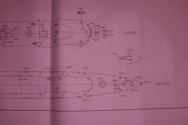
· Four sheets are supplied that show where all the parts go, where to place the photo-etch railings and what color to paint what.
Resin Castings
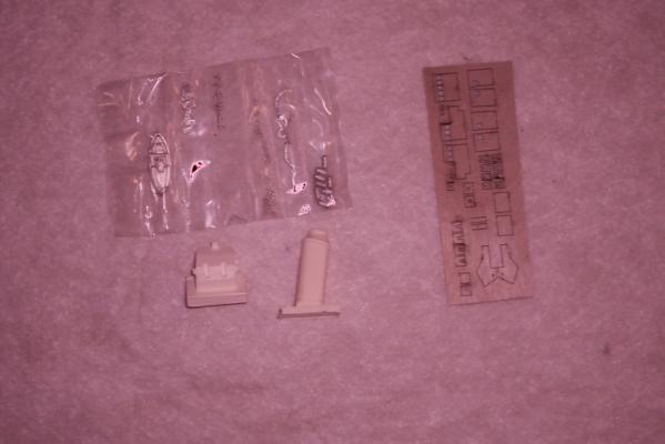
· Resin castings are used to supply the 5” gun mounts, the stacks, the GFCS director and other fittings too large for cast metal
· Having built a couple of resin models I’m not a big fan of resin since it usually has a lot of holes or voids from casting but all the pieces that came in my kit were well done, just needing some fine sanding to smooth their surfaces. No voids and no over-pour except for the casting plugs which are easy to remove.
· In case I forget to mention it later when I start working with the castings –remember that the chemical agent applied to the resin to keep it from adhering to the mold is also very effective at keeping paint from adhering to the resin. Always wash resin parts with warm (not hot) water and dish soap and let air dry before priming and painting.
Brittania Metal Castings
- Most of the smaller details such as bitts, chocks, fire hose racks, gun mt bases, davits, etc are supplied as cast metal. They are well done with good detail and free of major flash
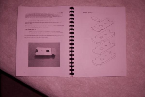
Laser cut parts
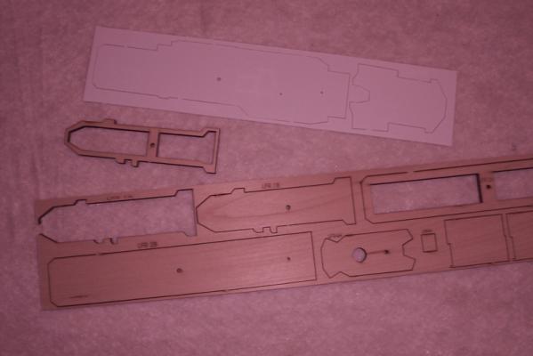
- Most of the superstructure components are made up of laser cut wood, stacked where necessary to provide height. Smaller details such as vents and some mast components are also wood.
- The other components using laser etch are sheet plastic parts such as superstucture decks and a neat adhesive template for painting the DASH deck markings
Photo Etched Brass (PE)
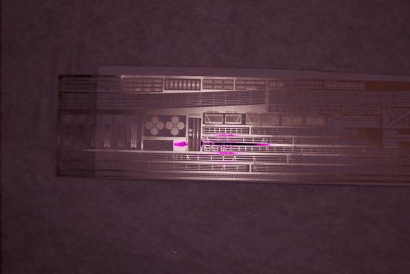
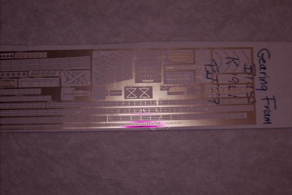
- There is a large fret of PE containing small or thin details such as doors, lifelines, inclined and vertical ladders, flight deck nets, and DASH details
- One unadvertised bonus is that the PE includes the parts to make either the SPS-29 or SPS-40 air search radar antennas. That may not seem like a big deal but they are a visually significant item and since the FRAMs were about evenly divided between having one or the other this allows you to accurately represent any ship in the class.
Miscellaneous Parts
- There is an assortment of brass tubing and rods, plastic strips, stripwood, a 50-star flag, decals for USS Gearing and some rigging thread
Bottom line: No complaints or problems with the kit contents, it looks like it provides everything needed for a nice display model except paint, glue, tools and mounting hardware
My next post will deal with starting to sand the hull. It may be a few days since it’s too cold to work out in my garage.
-
You really nailed those flags Patrick - I'm glad that technique worked for you.
For those folks who want to try this themselves I forgot to mention the type of glue to use. Rubber cement or one of those kid's glue sticks from the school supply section of the supermarket work best. Avoid CA - that just turns the flag into a stiff board that can't be furled. White glue has a lot of water in it and can soak thru the paper causing the ink to blur or run.
-
Well here goes … my first build log, hopefully it won’t be sunk by my non-existent photography skills.
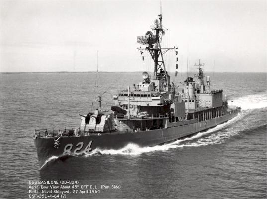
I’ll be building a model of the USS Basilone (DD-824) as she appeared in the early 1960’s, just after her Fleet Rehabilitation and Modernization (FRAM) upgrade. I’ll be using the USS Gearing (DD-710) FRAM 1 kit from Bluejacket Ship Crafters. I plan to add some details to the kit and possibly replace a few components with some scratch building.
I selected this ship/kit for several reasons:
- The “FRAMs” formed the backbone of the US Navy’s destroyer fleet for most of the cold war. While not as glamorous as the guided missile ships, they were still the epitome of a “tin can.”
- Although they were leaving service just as my time in the Navy was beginning, they had enough in common with my ships that I can bring my experience to bear in adding details - something I can’t do with a sailing ship model
- At 1/192 (1ft =1/16 inch) the scale of the model is large enough that it lends itself to adding details, something that is hard to do at 1:350 and smaller scales. On the other hand, with a length of 24” the model is still compact enough to fit on a bookshelf.
- The Basilone had a long career that lasted well into the 70’s and as such is a fitting representative of the class
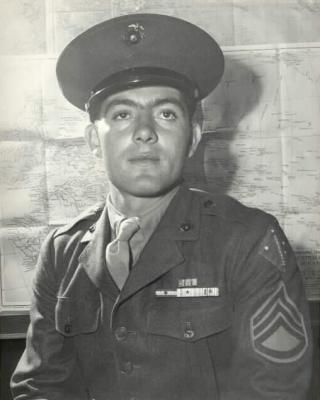
- To honor a great Marine hero. The ship was named after Sgt John Basilone who was awarded the Medal of Honor for his actions on Guadalcanal in 1942. He then resisted efforts to keep him selling War Bonds for the rest of the war and insisted on returning to combat duty. He went on to win the Navy Cross on Iwo Jima where he was killed in action.
References I’ll be using:
-
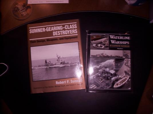
Sumner-Gearing Class Destroyers; Their design, Weapons, and Equipment by Robert Sumrall, US Naval Institute Press, 1995. This book is just what it’s title says, a technical study of the ships – not an operational history. I consider it “nice to have” rather than “must have” for someone modeling a Gearing destroyer. It has many good pix and is a great help for detailing weapons and antennas.
-
Waterline Warships – An Illustrated Masterclass by Phillip Reed, Seaforth Publications, 2010. This is a great book that I would recommend to anyone who wants to try their hand at either scratch building an entire ship or just adding details. He shows his construction of a 1:192 scale British WWII destroyer. It is amazing what he does with just wood, paper, sheet plastic, brass rod and wire. I hope to try a few of his techniques on my build.
-
1:96 General Drawing of USS Gearing, 1970, from The Floating Drydock website. With a price of $22 I expected a little more but this is just one sheet of plans, showing the starboard side and an overhead view of each deck. I had the print reduced by 50% so it is at 1:192 scale and I can pull dimensions right off the drawing. It has some, but not a lot, of detail so I will also have to use contemporary photos from online.
-
USN General Drawings for USS Basilone, last update 1971, from the US National Archives in College Park,MD. The plans show several differences from the Gearing and have a higher level of detail than the Gearing plans from the Floating Drydock (not sure why, maybe the Boston Naval Shipyard was more meticulous in the blueprint-making than whatever yard did the Gearing).
-
Online photo resources:
- www.navsource.org is a great resource. Although the coverage varies between individual ships, there are usually quite a few that cover the life of any given ship. Most photos are of the postcard variety, taken from too great a distance to reveal details, but some ships have onboard photos in their albums.
-
Former crew websites. Although it can be tedious to Google the name of each FRAM it is worth the time in that about half of the ships have active “alumni associations” many of which have photos from former crewmembers. These can be pure gold for clear, close-up photos of ships of the class. Bookmarking them has given me some excellent material.
- USS Joseph P. Kennedy Jr (DD-850), a museum ship moored at Battleship Cove in Fall River Mass. I plan to take a trip up there with a camera, tape measure and notebook to get a good handle on deck details and dimensions.
Brief background on Gearings and FRAMs
-
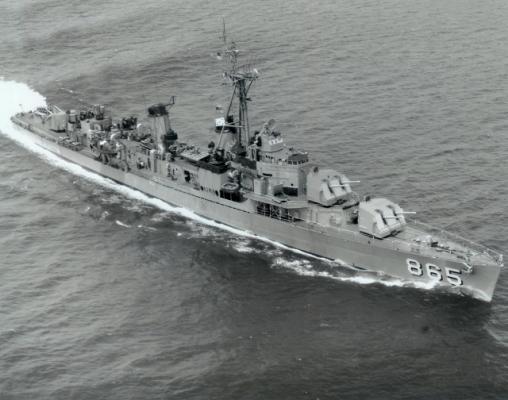
The Gearing class destroyers (a minor modification to the Sumner class) came into service late in WWII. The design was the result of hard lessons learned in the war, with the result that the Gearings were probably the best destroyer design of the period. They were fast and heavily armed and posed a significant threat to ships, submarines and aircraft.
-
By 1960 the technology of naval warfare had changed to the point that the Gearing destroyers need major modifications to remain relevant. The advent of jet aircraft made AAA guns of limited value, guided missiles being much more effective. Anti-ship missiles required improved radar and electronic countermeasures. Improvements in submarine speed and weapons range made it necessary to improve the DD’s detection range and ASW weapons range. Hence the Fleet Rehabilitation and Modernization program was launched. There where 2 major variants, FRAM 1 and FRAM 2 with the FRAM 2’s main difference being only a partial rebuild of the superstructure whereas the FRAM 1’s , like the Basilone, had everything above the main deck replaced.
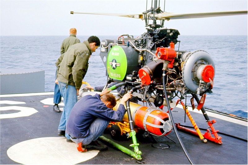
- The ships were rebuilt to focus on ASW with long-range sonar, a rocket-launched torpedo (ASROC), over-the-side MK32 torpedo tubes for quick-reaction to close-in sub detections. Additional radars and electronic sensors and countermeasures were also included, as well as a flight deck to support this little cutie, a drone helicopter - the DASH, to carry torpedoes and, believe it or not - nuclear depth charges. DASHs had a reputation for flying over the horizon, never to be seen again so maybe this sailor is engaged in some type of pre-launch prayer or sacrifice ritual.

My next post will show the contents of the kit.
Tim
- justsayrow, tarbrush, mtaylor and 5 others
-
8
-
Hi Patrick,
There is a neat trick for making paper flags look a little more realistic. After you print them out, but before folding them, cut out a piece of aluminum foil whose dimensions are slightly less than one side of the unfolded flag. Glue the foil to one half of the back of the flag and then fold it and glue it together. The foil will help hold the curves and folds that will make it look like it is "in the wind."
The next step is from Chuck's Syren practicum (if it is available online at the Model Shipways site then refer to that because he explains it better than I can), get several dowels of different diameters and starting with the largest dowel on the line that runs between the upper "inboard" corner of the flag to the lower "outboard" corner, start alternating folds in each direction, using smaller dowels as you work your way towards the the other 2 corners. You may have to make several tries, and bear in mind that if the the halyard which the flag is hanging from is vertical, or at an angle, that will affect the axis of the alternating folds as they relate to the edge of the flag, while you should always start the initial fold from the upper inboard corner the lower end of the line may have to be somewhere along the bottom edge, not necessarily the corner, that will give you the proper "drape". Keep trying until it looks natural, the foil is pretty forgiving. You can make the flag look like it is in a stiff wind, hanging limp in calm air, or anywhere in between. Here is one of my flags that I used this method:
Hope this helps
Tim
-
Kevin, you might try the Museum Store at the Chesapeake Bay Maritime Museum in St Michaels MD. They sell a great kit of the Hooper Island Draketail "Martha," which I bought and built. They also had kits for skipjacks and crabbing skiffs. I seem to recall they had sailing canoe kits too, or at least plans. Unfortunately the store's website has been down "for renovation" for at least a year but you can call them at 410-745-4962. There is also a modeling club associated with the museum, they might be able to help.
One other idea is that there is a club that races small sailing canoes in St Michaels, a Google search should turn them up, they usually build their own boats so you could get plans there.
If you have not been to the CBMM it makes for a nice day trip, some nice models and real boats to look at and great seafood places in town.
Tim
-
Hi Ger,
I've built a couple of BJ's solid hull kits (but not the Connie, maybe someday when I have the room). Carving a solid hull to shape is not easy but with your previous woodworking experience and some patience it should not be a problem. You may want to Google for some videos showing how to do it.
I generally use a Dremel tool with a flap sander to get close to the right dimensions then shift to rasps and files to get even closer and finally use flexible sanding sticks to get the curves right and bring it to the final dimensions. That's just my way of doing it, others use carving tools for the entire job - whatever you are comfortable with.
If it seems like you can't reconcile the hull templates with the main deck dimensions you should always keep the main deck dimensions (outline) true - If your main deck is too long, short, wide or narrow you will have multiple problems for the rest of the build.
One important thing to keep in mind (and to keep you from tossing it in the fireplace) is to remember that with a solid hull if you take off too much you can easily fix it by gluing a piece of wood over the mistake a sanding it to shape. With the addition of paint, let alone planking or copper plates, no one will ever know.
I'm looking forward to watching your build, good luck
Tim
-
Here's another option for the tiller rope problem.
The attached photo is of the Syren model at the US Naval Academy Museum. I seem to recall that Chuck mentioned this model as weighing in his decision to select the Syren to develop his own model. Anyway, in case this photo doesn't post clear enough to see, it shows the tiller as LONGER but not necessarily higher, giving the aft guns sufficient recoil room, although it pushes the end of the tiller very close to the steering wheel. It also uses 3 blocks on each side - one on the end of the tiller, one on the upper bulwark aft of the end of the tiller and one the upper bulwark
forward of the end of the tiller. The steering ropes are secured to the end of the tiller, run thru the aft block, thru the tiller block, thru the forward block and then to the wheel creating an X pattern when looking at the finished product port and starboard. Hope this helps
Tim
P.S. If you click on the photo it expands a lot
-
As far as your carronades sitting too high in the ports - I remember that problem with the Bluejacket carronades from an earlier Syren build log, it was on pg 9 of Rafine's build log (I made a note in my practicum at the time). I ran across it again yesterday on Google, I think under images for "24lb carronade" but damned if I can't find it now. Anyway, Rafine fixed the problem by modifying the lug on the bottom of the barrel to lower it closer to the sled. Looking at the pix of your completed carronade it looks like you have a lot of room to lower the barrel, probably enough to put the trucks back on and avoid messing with the waterways. Worth a try.
-
Chuck,
I have no doubt that what you cast and sent MS was correct in all respects but I can't compare your photos to what I have in hand.
What MS sent out as replacements, while much cleaner than the originals and their length is accurate, their width is almost 50% too small per the drawings and they don't look anything like the photos in you practicum - their width is almost uniform from muzzle to base while the photos in the practicum and the drawings show the typical wide base associated with carronades, regardless of shot weight .
Don't assume what you sent them is what we got, ask them to send you a sample and match it to your drawings - if your happy then I'll just assume I've got some vision problem.
Thanks
Tim
-
Chuck (and everyone else) -
I just got my replacements today and I wish I could say I'm satisfied with them but I'm not.
It appears that all MS did was "clean up" the castings without fixing the obvious underscale problems. There is now a hole on the cascabel instead of a stick but they are still exactly the same dimensions as the old ones , i.e. so skinny they look like swivel guns. All the MS folks had to do was lay the new ones on top of the drawings and they would see how inadequate they are. They are only about 60% wide as the drawings call for. These things don't even resemble carrondades.
This is a real let down, I'll probably pack the kit up and send it back to MS since guns are the heart of any warship model and its not too much to ask that they get them right.
I hope the MS folks follow this thread, pull out the "new" ones and compare them to yours and their own drawings and fix this.
Tim


USS Basilone DD-824 by schooner - FINISHED - BlueJacket Shipcrafters - Scale 1:192 - from USS Gearing kit
in - Kit build logs for subjects built from 1901 - Present Day
Posted
Don, thanks for the pix!! That is a gorgeous build, way beyond what I could do. I was particularly impressed with you sheet brass work, your scratch inclined ladders and your radar antennas. Your album virtuosity is also clever, I really enjoyed just sitting back and watching the slide show of the build pix
Thanks again