

schooner
-
Posts
645 -
Joined
-
Last visited
Content Type
Profiles
Forums
Gallery
Events
Posts posted by schooner
-
-
Thanks Brian. I'm impressed with your Bismarck, I've heard of the kit but I was not aware it had so much PE, you'll earn a PhD in PE by the time you finish it.
Tim
-
Wow.
I've been putting off making these for my Willie B because my soldering skills are a little shaky but if you could keep the old solders from melting when making the new ones using alligator clips and damp towels maybe I can too.
Great job on the dredges!
-
Hi Rick,
I'm moving a little slowly on the Basilone because Trout stocking season has just started here in Virginia and the weather is perfect, and of course postseason baseball has just started with the Nationals actually in the middle of it. Hopefully I'll be making another small post in a day or two.
Keep plugging away on the Willie B. - I learned more from that build than all the others I have done.
Tim
-
Rick,
Glad to have a real destroyerman following along on this build!
Your work on the Willie B will put you in good stead for taking on the FRAM kit. Just like the Willie B's instructions the ones for the Gearing kit tell you what to do but not always how to do it. You will also find that the Gearing requires less scratch building than the skipjack does so, with the exception of carving the solid hull, you should not see anything that you haven't done before -plus you won't have to sew any sails!
Tim
-
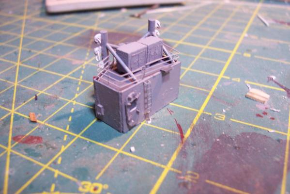
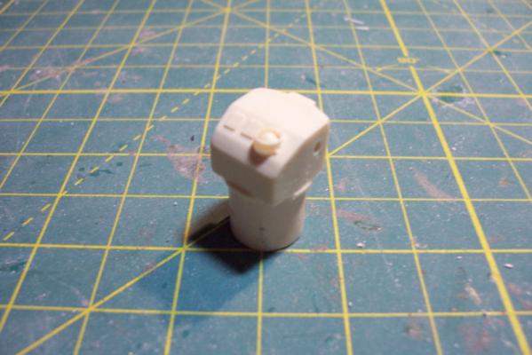
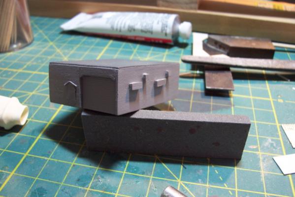
ASROC Control Station
The FRAMS had control station for the ASROC Launcher that also served as a security control point since the system was nuclear capable
The kit provides a resin casting for the control station that is perfectly servicable.
Unfortunately for my use, the windows on it are a style that the Basilone did not have so I will scratch build the station.
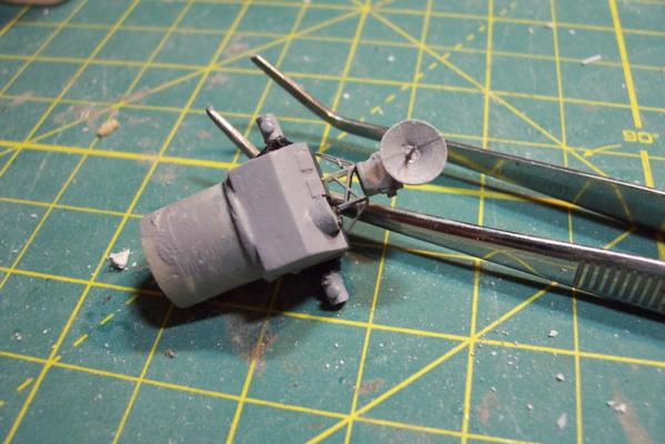
Using sheet plastic and the kit’s casting as a guide it was pretty easy to fabricate a new one. The kit also provides 2 pieces of Brittania metal to serve as the Replenishment at Sea (RAS) king posts which are located on the front of the station. I decided to build my own out of plastic because I find it easier to work with and I wanted to add an extra support leg to each kingpost. Here’s the station with the kingposts:

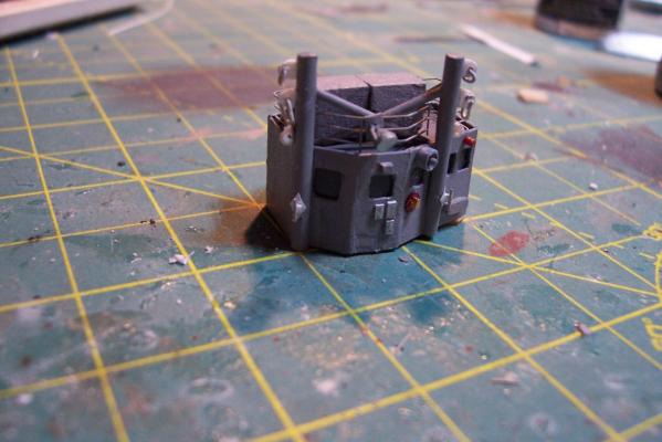
After that it was just a matter of adding some scratch details. I needed a loudspeaker for the front of the station so I made enough for the rest of the build while I was at it.
The details include:
- lifejacket lockers on top
- Launcher train warning bell
- Launch warning siren
- windshield wiper motor
- Floodlight
- Padeyes, longlinks and cleats on the RAS posts (the white stuff)
- several photo etched aluminum safety placards (never read)
- Sound powered phone storage box
- junction box
- WT door

- WackoWolf, Captain Slog, mtaylor and 3 others
-
 6
6
-
Thanks Ken, that's all I needed to know!
Tim
-
Carl,
Looks like you picked a beauty, should turn out to be a great model.
Could I ask you to pull a quick measurement off the plans? I'd like to know the max length of the model, from the tip of the bowsprit to the aft most end of the boom on the main mast. I'm asking because the Model Shipways catalog shows the length as 36.5" but I happen to have a copy of the box cover (sent as packing material when I ordered another MS kit) and it shows the model's length as 43". Could you tell me which is correct?
thanks
Tim
-
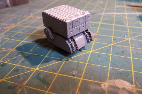
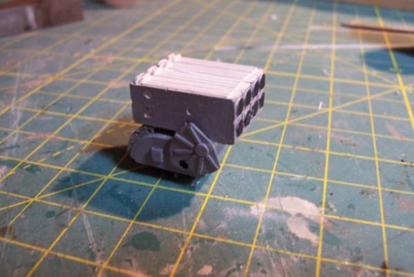
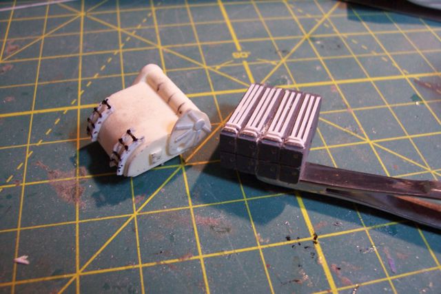
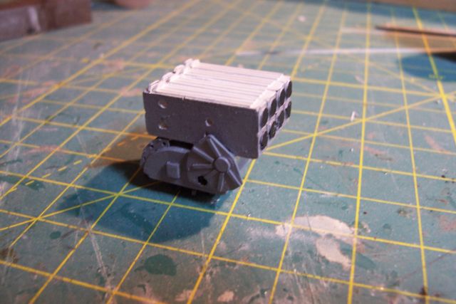
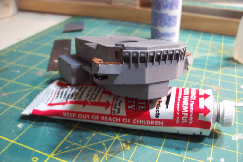
ASROC Launcher
The kit provides 2 resin pieces and a Brittania base.
Given the large size of this item I thought it would lend itself to some scratch additions, unfortunately I got a little carried away and added about 50 pieces which is a bit much at this scale
Here is what the parts look like after the addition of the scratch items to include:
-
circular and rectangular inspection and access plates on the sides of the base
-
curved ladders on the front of the base
-
perforated I-beam stiffners on the top of the box
-
cooling water channels on the top of the box
-
drilled out the access ports on the doors where firefighting applicators could be inserted in case of a motor ignition

And here’s the completed assy after painting:
-
circular and rectangular inspection and access plates on the sides of the base
-
Bill, great looking build!
Couple of questions:
- Where did you get your plans?
- What types of things are you using HR products for (I know there isn't much available from anyone in 1/16 scale)? How would you rate their quality?
- I've been looking at this BJ kit for sometime as a possible future build - did you find thinning the bulwarks difficult?
Looking forward to following this one!
Tim
-
-
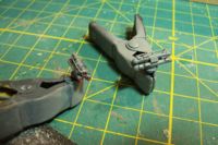
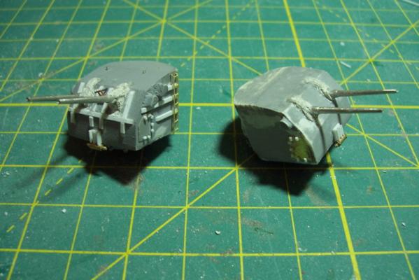
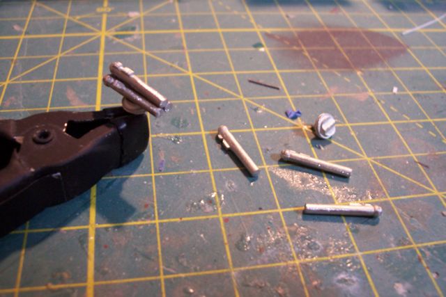
MK32 Torpedo Tubes
Summer activities have slowed work on the model but I'm getting some small stuff done. The 2 torpedo mounts were easy. They consist of 3 tubes and a base, all cast brittania.
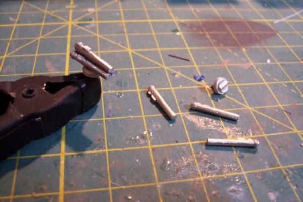
The bottom 2 tubes rest on the base and the top tube rests on the two lower ones but since the breach ends are larger than the muzzle ends some spacers were added to keep the axis' of all three tubes parallel. The photo above shows what the mount looks like without the spacers.
Scratch additions include various junction boxes, fine wire to simulate knobs, a long storage tube on the upper tube, and the fiberglass muzzle covers


- Captain Slog, Leo-zd, mtaylor and 2 others
-
5
-
Thanks for reposting your pix, this was always my favorite build log.
Your woodworking, painting and chain-forging skills are unequaled. Can't wait to see the rest!
Tim
-
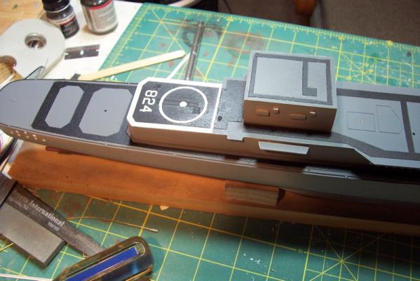
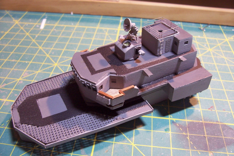
More Non-skid
Finished the non-skid tracks on the rest of the decks and the final waterways and scuppers. All the superstructure pieces are just dry fitted at this point.
Flight deck markings are a combination of:
- Spray paint (landing circle)
- Dry transfer decals (numbers)
- Pin striping tape (deck edges)
Finished up with a coat of dull-coat.
The lines in the center of the flight deck are etchings in the laser cut deck to represent the plates covering a collapsible replenishment kingpost. Only scratch adds are 2 escape scuttles.

Next item will be adding striping to the deck edges to cover up the I-beam ends and add deck coamings.
-
-
MK37 Gunfire Control System Director
Very simple – consists of a resin main piece, Britannia radar dish and optical range finder arms and PE supports .
The only scratch additions are the RF feed horn in the center of the dish, canvas bloomers on the range finder and a simulated retracted canvas cover behind the Director Officer’s position. Hard to believe they fit 7 guys in that little box, when I served as the D.O on a slightly smaller director there were only 2 of us in there and it was still a tight fit.
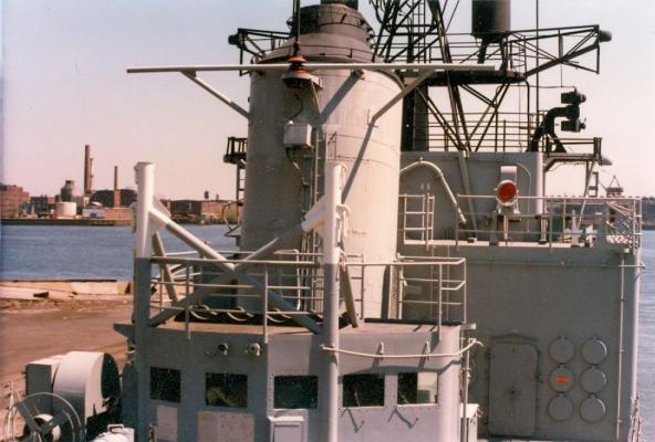
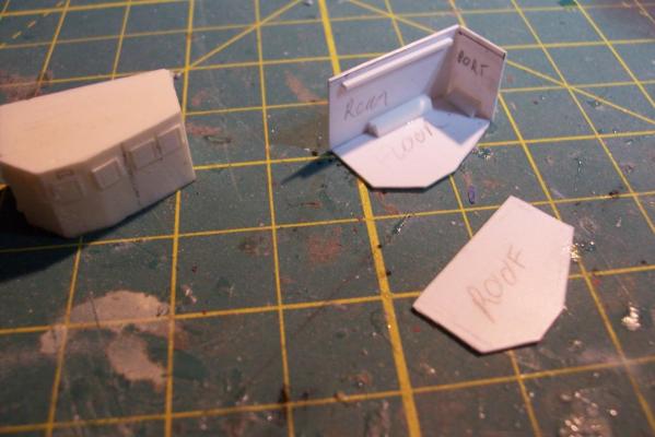
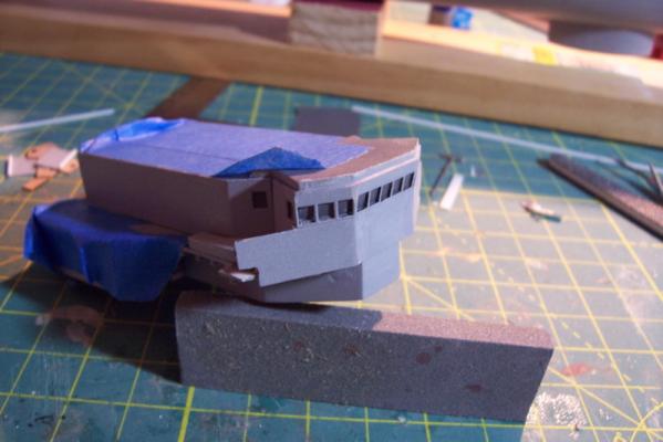
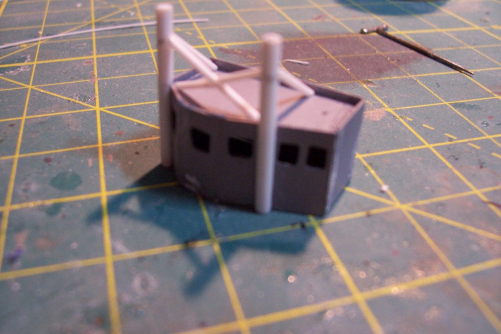
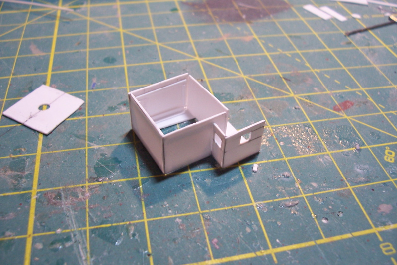
Operations Office and Signal Shelter
The kit comes with a resin signal shelter that accurately represents the shelter on 95% of the FRAMS – about the size of 2 phone booths (I know the younger half of the readers of this post are asking themselves “What the Hell is a phone booth?”)
Unfortunately Basilone and a couple of her sisters who received their FRAM upgrade at the Philadelphia Naval Shipyard had a much larger structure installed: a rectangular Operations Department Office with a u-shaped signal shelter wrapped around its aft end. The mainmast went thru the center of the Ops Office.
Not sure who came up with that bright idea – the higher above the keel the greater the effect of the ship’s rolls and FRAMS rolled a lot. Given that the Ops office was located at the very top of the ship and had no windows it must have been a real vomitorium.
I made the structure out of sheet plastic, although wood would probably have been easier. The doors on the signal shelter portion needed to have rectangular windows (not available from the commercial PE frets) so I had to scratch those from plastic with bits of wire for the dogs.

Waterways
I decided to add waterways on the main deck, they run just inboard of the deck edge and serve to direct rainwater and saltspray to overboard drains (scuppers) to keep the sides from looking dirty. Thin .01x.03 plastic strip edge glued to the deck worked fine. They will have the advantage of serving as good anchoring points for the bottom rung of the PE railings when those are added later.
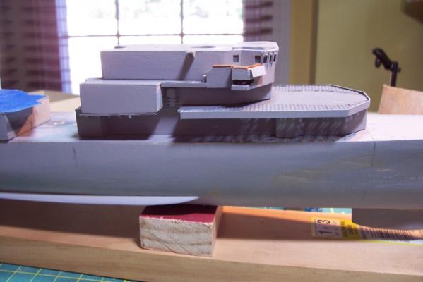
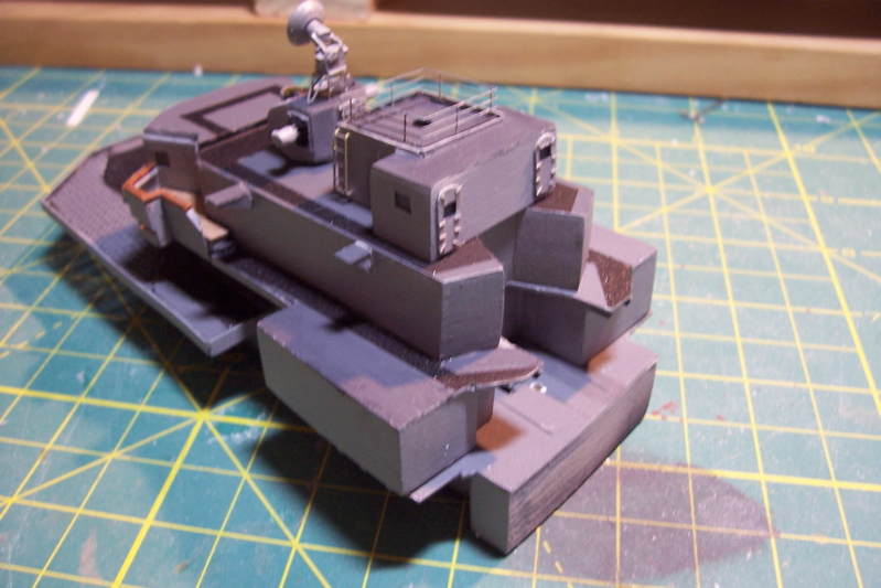
Non-Skid
Steel decks are very slippery when wet, add some oil, grease or even accumulated salt and they can be impossible to walk on in any kind of sea so Navy ships lay down rough, textured paint to provide safe walking areas.
I wanted to try to include it but wasn’t sure how. I experimented with 400 grit sand paper cut to shape and glued to wood then spray painted the appropriate color. It came out looking really good but I was concerned that it might peel up at some point down the road.
Looking around some plastic modeling sites for ideas I ran across this stuff, it is sold at hardware stores and sprays on as a texture, you can hear it crackling as it dries. I have no idea what anyone would use this stuff for but it works well for non-skid.
After masking off the areas where it won’t be it was sprayed on, then a coating of flat black primer was added since the texture paint has some shine to it. It would be hard to get it "wrong" since there was no standard pattern for putting it down so each ship was different and even the same ship might change non-skid patterns every time the laid it down.
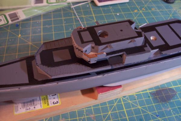
Here’s what the upper superstructure looks like with non-skid, the MK37 Director and the Ops Office/Signal Shelter dry fitted.


-
Thanks Patrick.
Although I enjoy doing this kind of stuff I've figured out that 1/192 is the smallest scale I can handle - I have no idea how the folks working with 1/350 scale, let alone 1/700, do it.
-
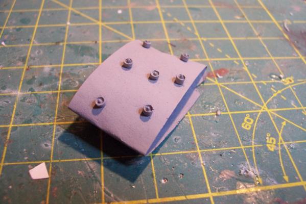
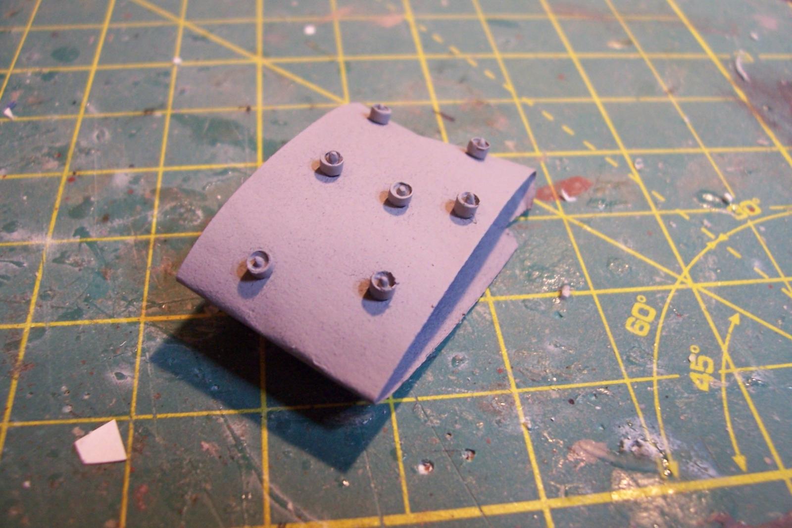
DASH Hanger
Very simple assembly. The usual 3 lifts of wood topped by a sheet plastic deck.
The only anomaly was during my trip up to the USS Joseph P. Kennedy Jr in Fall River Mass I noticed that she had 9 blow-out hatches on the forward face of the hanger/ASROC magazine, not 6 as per the kit instructions. After I got home I did some research and found out that the Basilone had 9 too. Problem was that there was not enough room to fit the extra 3 hatches because the kit assembly has the starboard half the hanger extending about 1/16” forward of the port on the forward face. Checking the plans the forward face should be flush so I removed all the PE and sanded the forward face flush and made up 3 extra hatches out of plastic to match the 6 PE hatches.
The large WT doors on the fore and aft faces are from the 1/192 USN Door set from Tom’s Modelworks. Fortunately the fret had a few large doors which correspond to the doors on these ships at that location, needed to move the ASROC missiles in and out of the magazine.

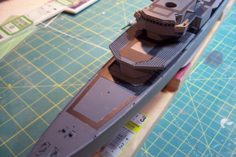
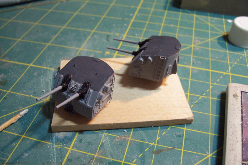
5/38 Gun Mounts
The mounts are cast from resin with Brittania metal barrels and mounting rings. I removed the gun captain hoods from the top of the mount because Basilone didn’t have them. The bottom of the castings are drilled out to accommodate the mounting rings with a length of 1/16” brass rod to pin them together. The rings have a shallow collar that the mount rests on but to my eye that made the bottom of the mount sit too high of the deck so I removed the collar, I also extended the brass rod so that I could use it to pin the mount to the main deck.
The barrels have a circular base that is trimmed at whatever angle you want the barrels to be at – I made the aft mount level and the forward mount elevated to match the rise of the focsle. I drilled out the ends of the barrels using the smallest bit I had (size 71) and then enlarged the holes with a rat tail file.

The kit provides PE vertical ladders, I added the reinforcing bars on the forward mount (meant to protect it from breaking seas), access panels on the sides, the canvas gun bags (bloomers) around the base of the barrels,the mechanical train stops on the bottom of the front of the mount, aftermarket PE doors, hatches and grabrails.
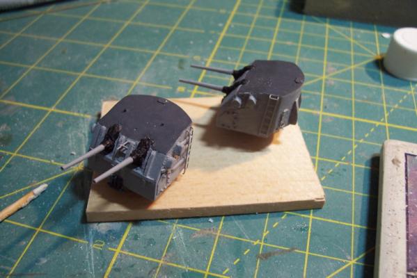
Next up will be the Gun Director assembly
- Captain Slog, hexnut, Aussie048 and 3 others
-
6
-
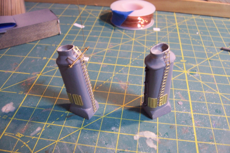
Stacks
Although the instruction book calls for these to be put together further down the road I decided to do them and the other deck details now before I paint the hull so that the time I have between painting the hull and finishing the build is minimized to reduce the chances of damaging the hull’s paint job.
The stacks are cast from resin. After washing them with warm soapy water to remove the mold releasing agent they only needed a little putty to fill in a couple of small pits.
Here’s what they look like after the kit-provided details have been added:

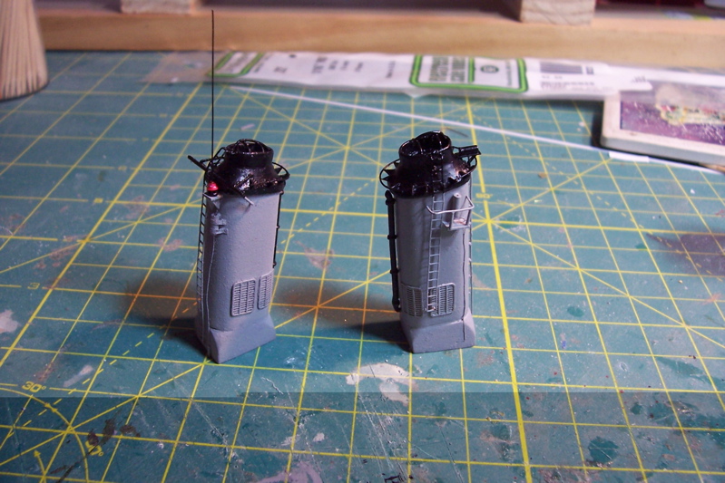
Here’s what they look like after my scratch additions to include:
· Stack cover support grids
· Grabrails
· Antenna couplers (tuners) with RF cables
· Ship’s whistle with steam pipe
· Work platform
· Insulators on whip antenna
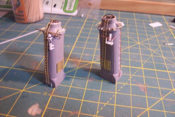
And finally, with their final paint job:

Next up will probably be the DASH hanger.
-
Hi Patrick,
Should you decide to model one of Connie's battle stations you might consider asking some help from the US Navy Museum at the Washington Navy Yard, they have a full scale mockup of 2 of Connie's guns on the gun deck. A little phone time and I'm sure you could find someone who would agree to take some photos if you mailed them a drug store camera and a return envelope. If no luck let me know and I could run down there and take some pix for you.
Of course the folks onboard the real USS C up in Boston would probably do the same thing too.
Tim
-
Thanks Patrick!
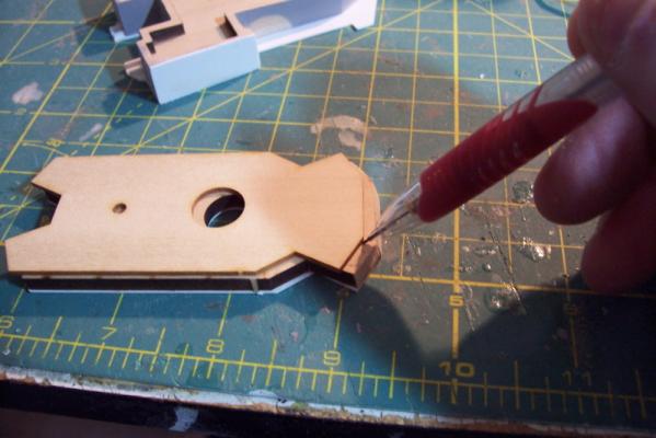
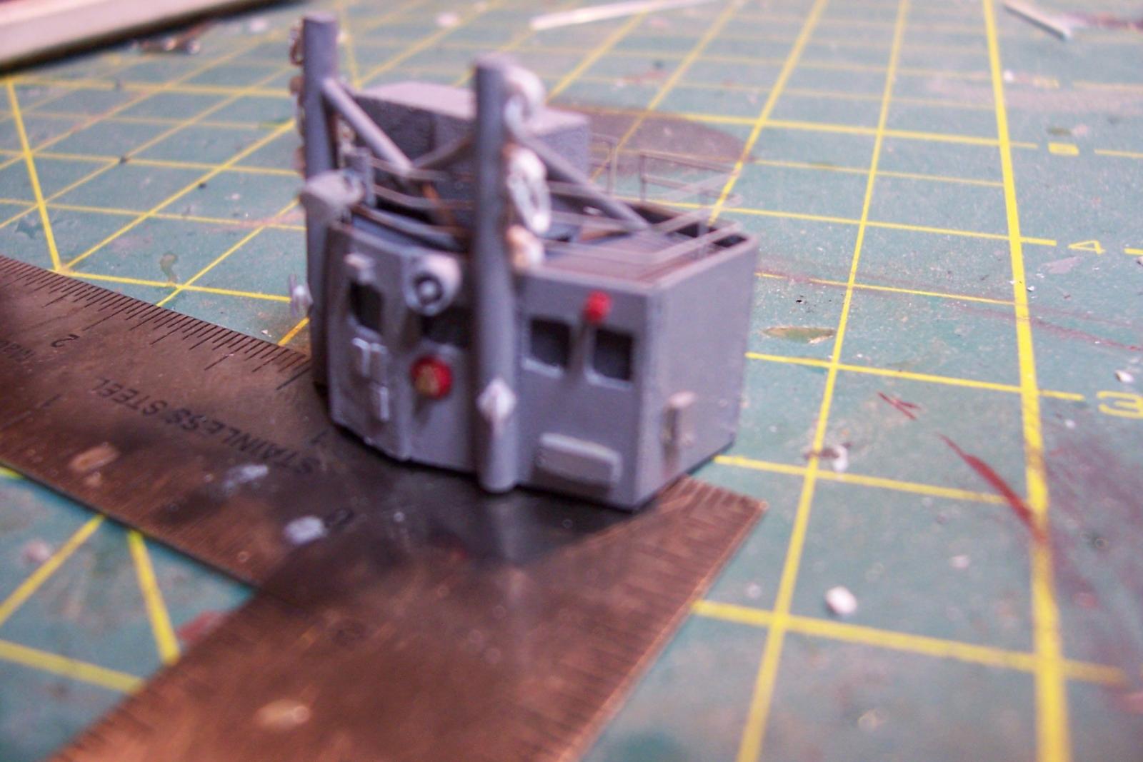
The Pilothouse
This took me a lot longer than I thought it would. Lots of little, fragile parts make for slow going and frequent repairs I guess.
The pilothouse, like the rest of the superstructure assemblies is made up of wooden lifts topped with a sheet plastic deck.
The order of putting them together is a little different in that the top 2 are glued together then the 3rd piece is laid on them and a line traced to determine how much of an angle must be sanded into the front 3 faces so that they have a subtle “tilt” forward. Here’s the line being drawn (exaggerated for illustration):
And here is the all four lifts glued together with the tilt in place.
I had originally intended to depart from the instructions in order to fabricate an open pilothouse where I could put plexi in the windows and have the bridge doors open but after actually handling the parts I realized it was beyond my abilities. The front and sides of the pilothouse are made up of 7 pieces of 1/64” plywood, 3 of which have to bend to create the tilt. If I had tried to use just those, assuming I could put them together without looking awful, they would have been VERY fragile and I’m sure I would have crushed the front of the pilothouse at some point in the build – so I decided to follow the instructions. Painting is not one of my strong points so to avoid trying to get good demarcations between the dark “interior” of the windows and the haze gray exterior I just painted the background pieces where the widows would be dark gray and then glazed them. Once the thin ply pieces were on it looked OK.
Adding the bridge wings was slow work. The stiffeners between the windows was quick. The small windshield wiper motor housings above each window are my addition.

Here’s what the completed pilothouse looks like resting on the bridge assembly, the scratch additions are the wood cap rails on the bride wings, the venturi wind deflectors on the front of the bridge wings and the 3 small deck extensions on the top deck. Details like doors, ladders, portholes, etc will be added later.
The next item will be the DASH hanger which should be easy.
- justsayrow, Captain Slog, Aussie048 and 4 others
-
7
-
Modifying the forward 01 level deck
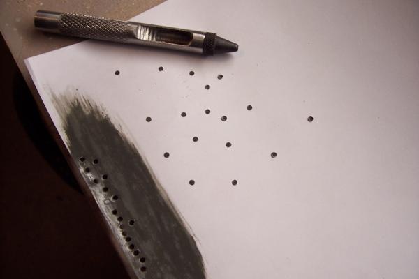
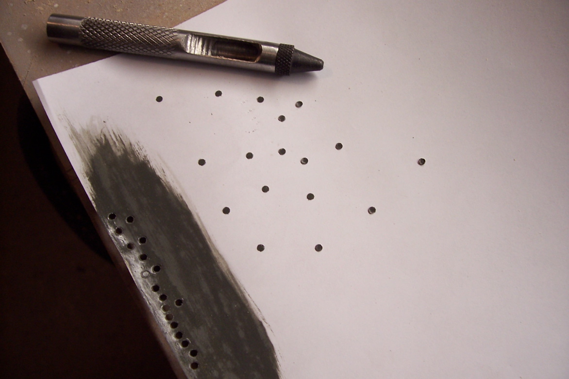
I ended my last post about the possibility of trying a new way to make portholes. It comes from the Waterline Warships book I listed on my first post. Basically a punch is used to punch about 2mm deep into the wood, a solid rod is then pushed against the circle, depressing the circle by 1 mm or so. The punch is then used to punch out discs of painted and glazed paper. The discs can then be glued into the depressed holes giving a pretty good simulation of a porthole with out the tear-outs associated with drilling them. Bottom line: I could not make it happen, I needed a 2mm hollow punch to get the right scale. The only thing I could find online for less than $50 was a leather punch set. It worked fine for making the paper discs but the outside diameter was too big. The technique is worth remembering if you can find (or make) the right punches. I couldn’t so I’ll be going with some aftermarket PE for mine.
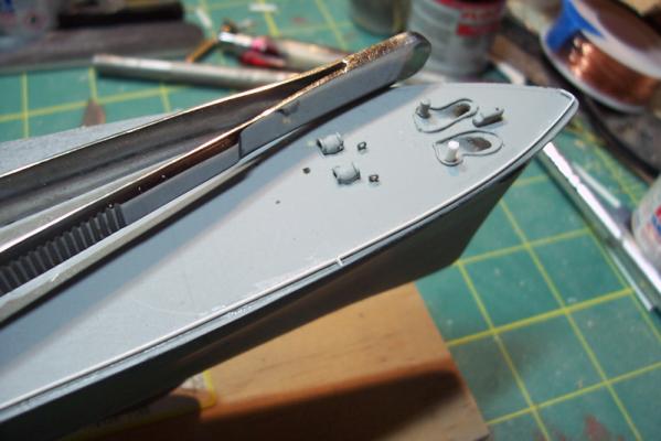
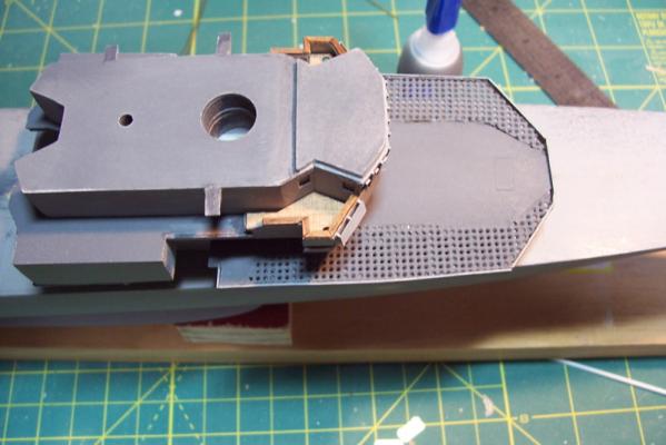
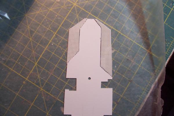
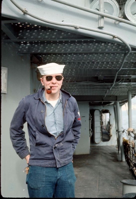
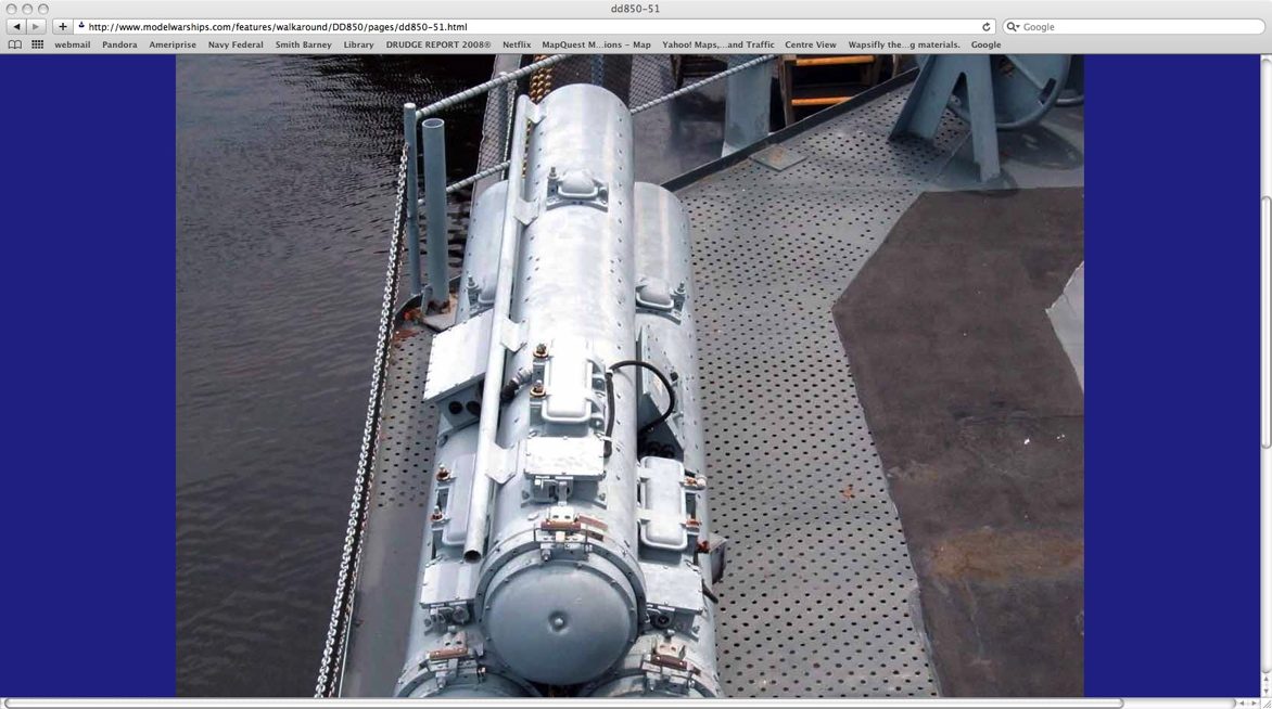
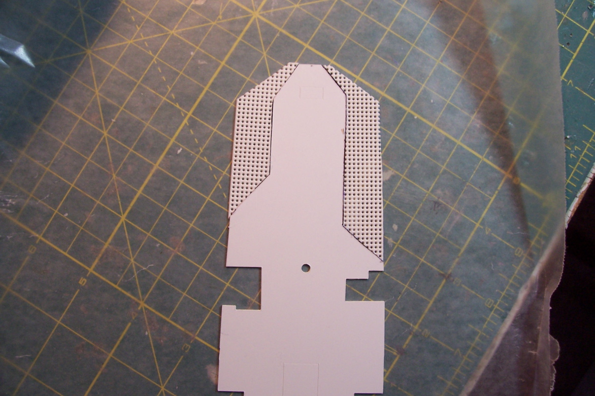
During my photo research of the FRAMS I noticed that the overhanging portion of the forward deck was made of perforated metal.
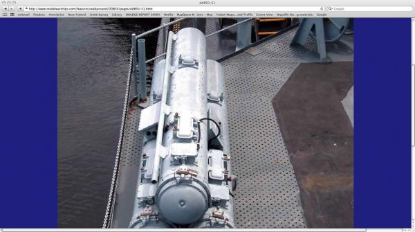
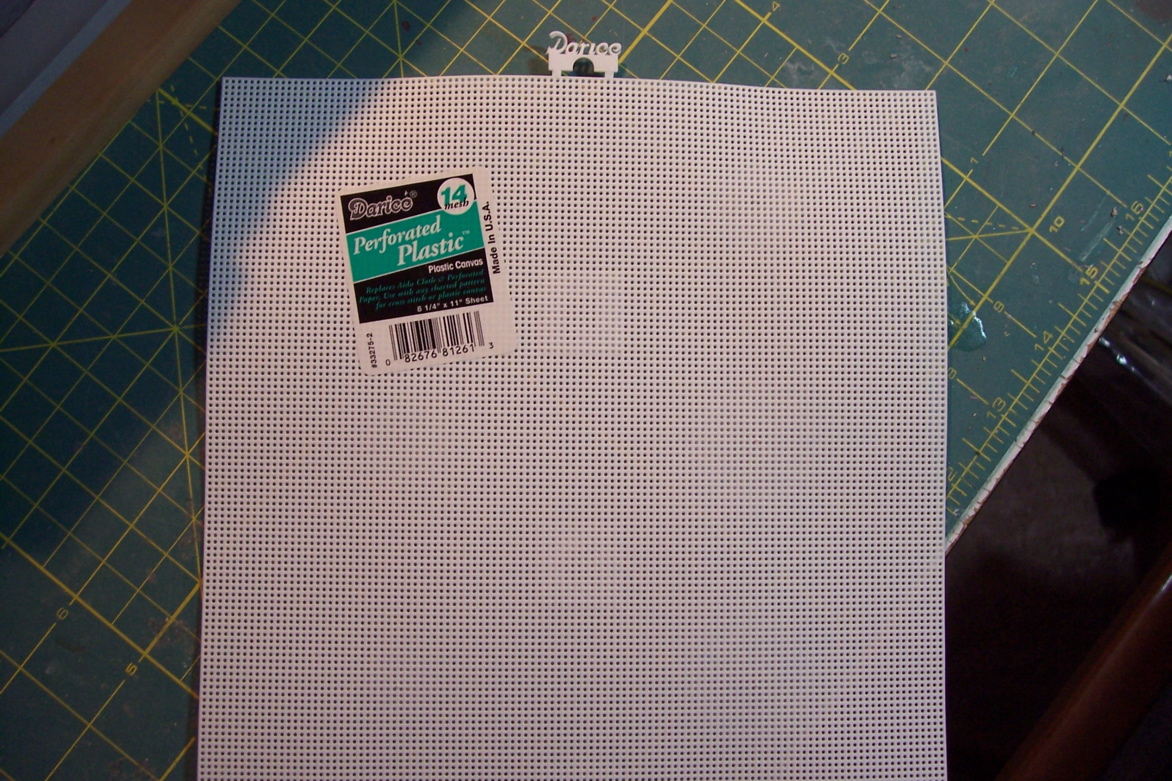
At first I assumed it was for drainage, but after a little more rumination I realized it was for drainage, but upward, not down. When green water came over the bow and hit the front of the superstructure there had to be some means of releasing the hydrodynamic pressure or the deck would have been peeled up like paper Mache, hence the holes. I wanted to incorporate that if I could but I did not want to have to drill a boatload of little holes. Once again, Google is the best modeling aid ever. I found this stuff used by needlepoint folks and was able to find it at the local arts and crafts store.
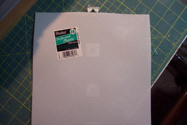
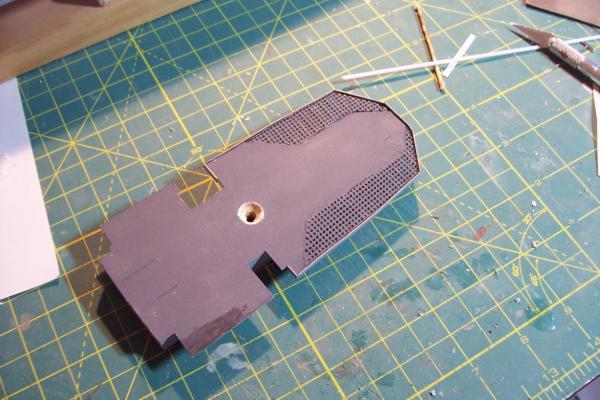
After cutting off the portions of the deck that formed the overhang I used the cut off pieces as templates to cut out the perforated material. After some trimming and adjusting it worked OK. The holes were a little over scale but I figured that after a couple of coats of spray-paint that they would shrink enough to be a good match.
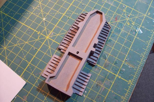
The other thing I noticed was the small I-beams used as stiffeners under the over hanging decks.
Using some Evergreen Plastics I-beam material I added those, easy to do but repetitive.
After adding strip plastic along the deck edge to cover the I-beam ends and extend a little above the deck to form a coaming I’m satisfied with what I have.
Next up will be fabricating the Pilot House.
- Captain Slog, rvchima, JPett and 9 others
-
12
-
Thanks Patrick. Compared to the big Connie this is a piece of cake.
-
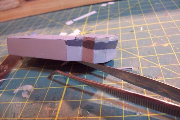
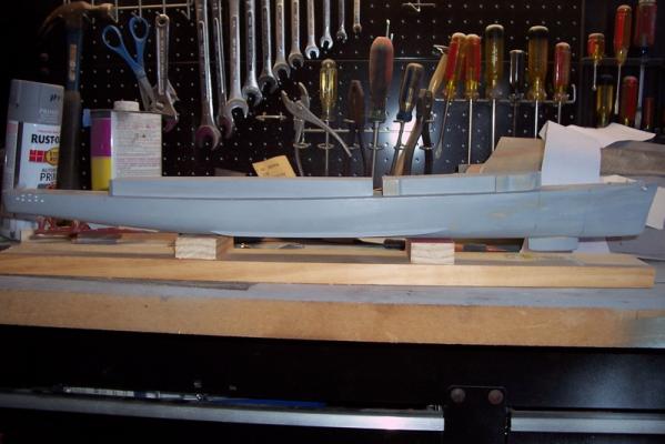
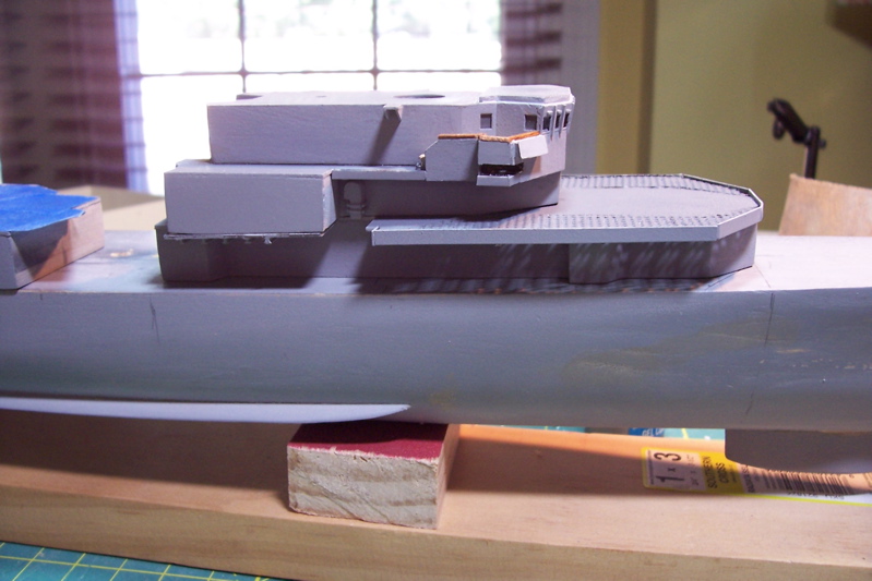
Shaping the superstructure
As I mentioned earlier, the superstructure is made up of several sections, each of which is made up of pieces 3 of laser cut wood, topped with a laser cut sheet plastic deck.
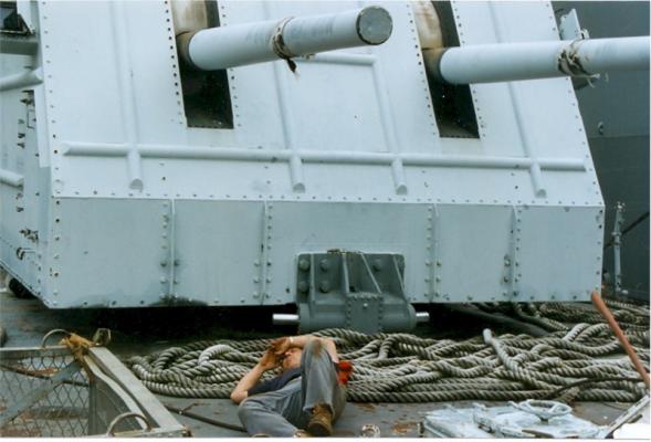
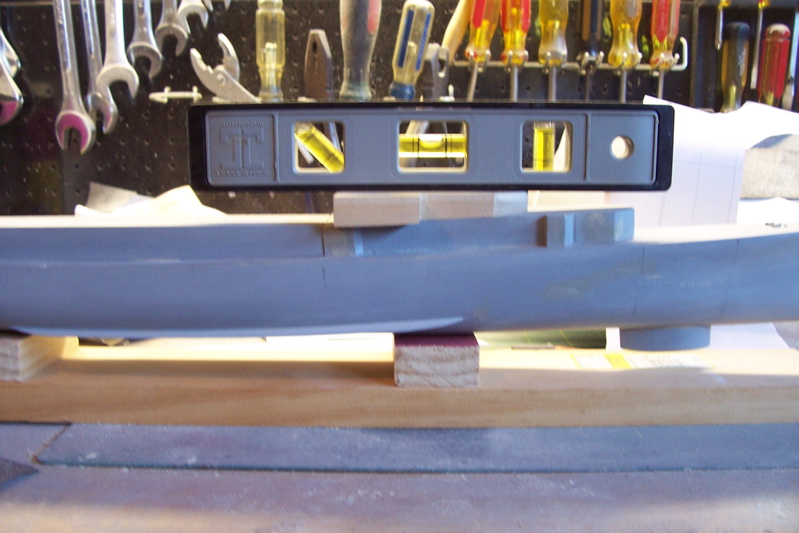
The shaping involves sanding their bottoms by placing sandpaper on the main deck so that they match the camber of the deck (minimal) and, more importantly, so that their heights are tapered correctly. The aft section tapers from aft to forward, i.e. the aft end is higher than its’ forward end. When done its’ top deck should be parallel with the keel.
The forward superstructure assembly also tapers from aft to forward but its taper is greater to allow for the shear (rise) of the deck as it approaches the focsle. Wood also has to be removed aft so that its aft end is the same height as the forward end of the aft section. When done its’ top deck should be parallel to the main deck, which in that area is rising. Here’s how mine looks after sanding (gap between sections is exaggerated for clarity, when assembled they will be in contact).
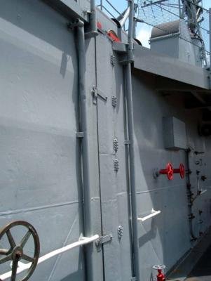
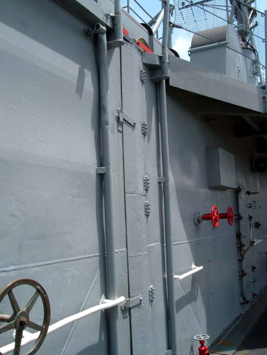
The joint between the two sections should be close, but since there was an expansion joint at that location, covered by a hinged plate, I’ll be covering mine up as well. Here’s what the real thing looks like:
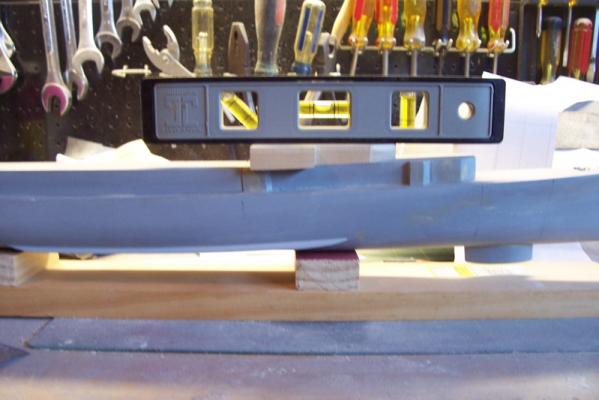
The next section is what the instructions refer to as the bridge, even though “01 level” is probably more appropriate. This section also has to be tapered aft to forward. At this point I departed from the instructions, which call for putting sandpaper on top of the forward superstructure assembly. Since that section has several areas of unsupported plastic sheet decking I was concerned I would get some uneven contact under pressure so I just sanded it on my work bench, putting more pressure on the forward part to impart the taper. The instructions state that up to 1/8” may have to be removed from the front of the bridge section so that its top surface is parallel with the keel (i.e. level), that was a good estimate – after removing 1/8” mine is now level.
Next I’ll be trying a new method (for me) of putting in portholes – one of my consistent problem areas.
- MarisStella.hr, mtaylor, hexnut and 1 other
-
4
-
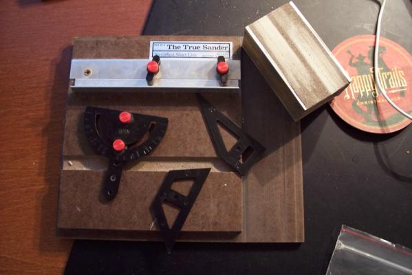
Patrick,
I bought this "True Sander" years ago for sanding angles in strip wood for the deck furniture on my first kit. Haven't used it in a long time but it came in handy for sanding the beveled corners of the superstructure. Not sure if they make them anymore.


USS Basilone DD-824 by schooner - FINISHED - BlueJacket Shipcrafters - Scale 1:192 - from USS Gearing kit
in - Kit build logs for subjects built from 1901 - Present Day
Posted
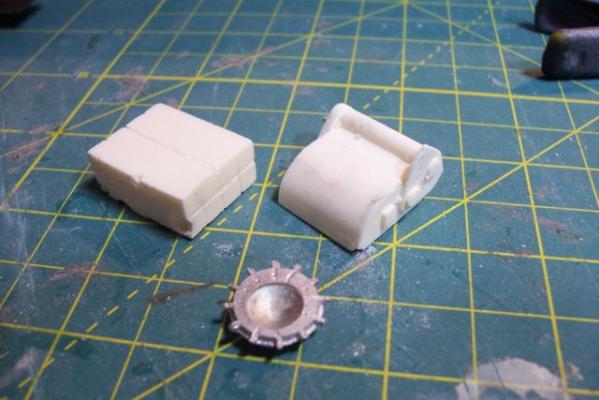
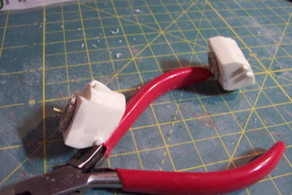
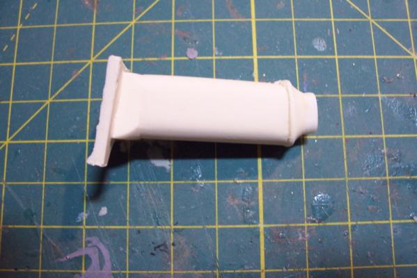
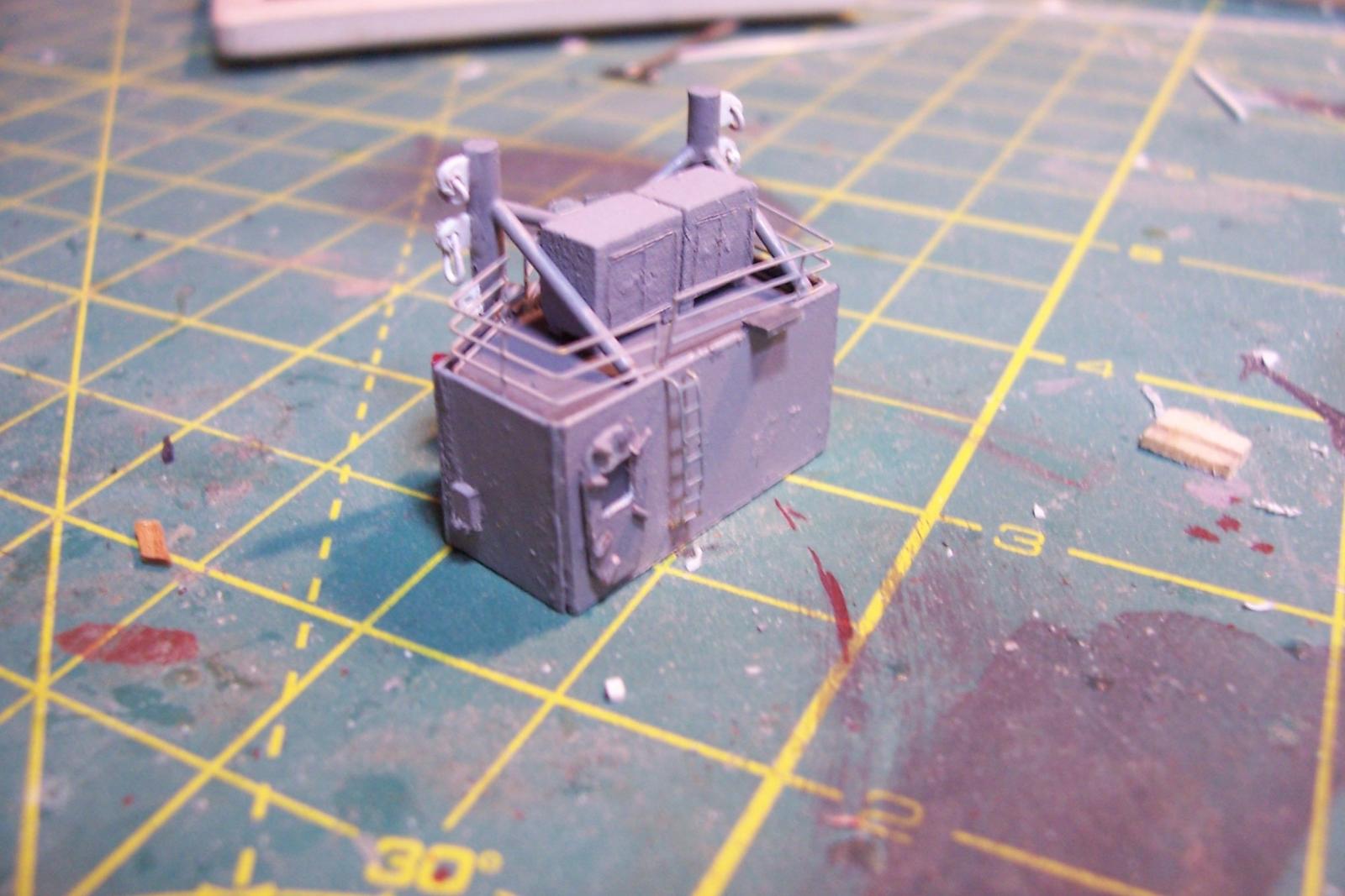
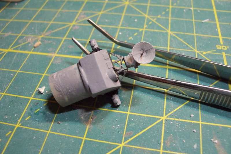
ASROC Loader
The loader was used to pick up ASROC missiles from a dolly or container and ram them into the box launcher.
The kit provides several britannia metal pieces and 2 brass PE pieces (not shown). I won’t be using the PE on my build because the long loading arm was usually stowed away except when actually loading.
Here’s the brittania parts:
Here’s what the loading arm with a missile looked like:
The loader had a real rat’s nest of hydraulic lines that I would like to include an impression of so I’ll scratch build the loader out of plastic, brass wire and paper.
Here’s what I ended up with:
DASH Drone
The DASH was used to deliver torpedoes or nuclear depth charges at ranges beyond what the ASROC could reach (always a good idea when dropping a nuclear weapon)
The kit provides a brittania body and several pieces of PE, the only details I’ll add will be some of the push rods below the rotor blades.
Here’s what it looks like assembled
And here it is painted (red and green sides so the operators could figure out what side they were looking at) . Fortunately I had some 1/700 decals which worked great for the dash insignia and warning stripes at this size.