HOLIDAY DONATION DRIVE - SUPPORT MSW - DO YOUR PART TO KEEP THIS GREAT FORUM GOING! (Only 75 donations so far out of 49,000 members - C'mon guys!)
×

schooner
-
Posts
741 -
Joined
-
Last visited
Content Type
Profiles
Forums
Gallery
Events
Everything posted by schooner
-
 Thanks for the kind words and the likes. I've been plugging away on the foot ropes and will then double check to make sure I have mounted all the blocks on the masts that I can at this point and then it will be time to actually start rigging (finally!).
 -
Wonderful build! Congratulations on reaching the finish line and thanks for taking the time on the log. I see more builders from North Carolina here on MSW than any place outside the UK, a little odd considering NC was never a hotbed of 18th or 19th century shipbuilding.
- 233 replies
-
- 2
-

-

-
- Indefatigable
- Vanguard Models
- (and 1 more)
-
Nice jig! What are the 2 pins on the bottom of it for?
- 587 replies
-
- 1
-
-
- Indefatigable
- Vanguard Models
- (and 1 more)
-
Glad to be of help Ramsey, it is a great kit. Don't hesitate to PM me if you have questions.
-
I for one think that is fine painting on such a small item. As for the skin tone it may be spot on, after all the ancients didn't have sunscreen.
- 587 replies
-
- 4
-
-

-
- Indefatigable
- Vanguard Models
- (and 1 more)
-
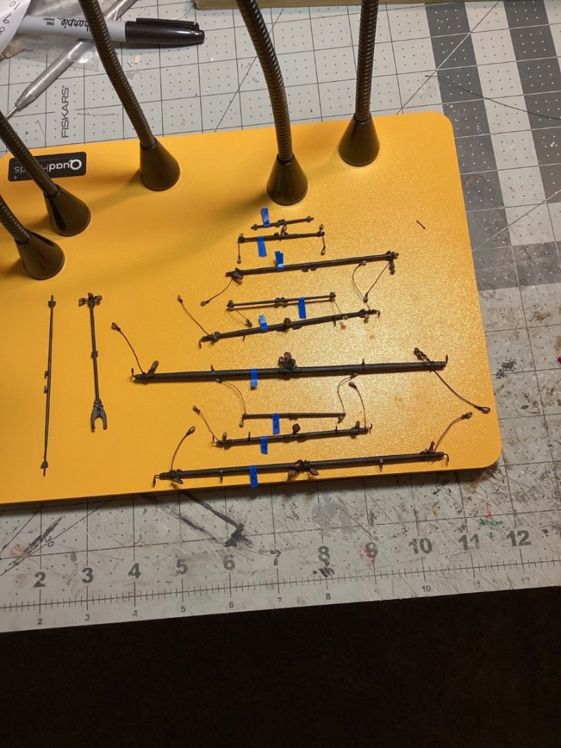
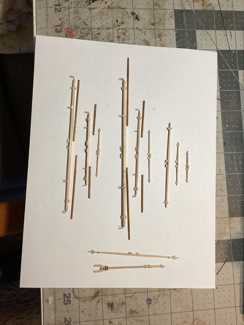
More yard work (the other kind) The yards have been painted and the blocks and eyes for the slings, jeers, lifts and braces have been added. This has been slow work for me because it is pretty boring and repetitive. Next up will be adding the foot ropes.
- 142 replies
-
- 9
-
-
- alfred
- solid hull
- (and 2 more)
-
Geoff, although I have not got to the point of adding the futtocks and cartharpins I did find a good explanation of how to to them on Glenn-UK's build log for HMS Sphinx, starting at post # 281 for the lower ones and #367 for the upper ones. You are doing a great job, keep up the good work.
-
VERY nice job Rick! After seeing your results I'll probably make this my next build.
- 43 replies
-
- 1
-
-
- Essex
- Model Shipways
- (and 2 more)
-
Great choice Rod! That is one classy kit. I'll be following along.
- 96 replies
-
- 4
-
-
- Sphinx
- Vanguard Models
- (and 2 more)
-
This is a great lesson on small boat kits whose ideas can be applied across many different kits and kit brands since they most of them follow the same basic construction sequence, even lift-type hulls can still benefit from your ideas on detailing the interior. Your techniques are very helpful since they do not require elaborate shop machines. You have shown what planning, patience and attention to detail can accomplish - I just wish I had them. I'll be saving this build log. Keep up the good work and thank you for taking the time to build it.
- 22 replies
-
- 1
-
-
- 24 ft Launch
- Vanguard Models
- (and 1 more)
-
Thanks, that's what I was hoping to hear. I do have a "Sand-it" and it has been good for detail work.
- 43 replies
-
- 1
-
-
- Essex
- Model Shipways
- (and 2 more)
-
Yardarms The yards have all been fabricated per the plans with cleats, chocks and studding sail irons attached. Now it’s time to paint them and add the foot ropes and blocks.
- 142 replies
-
- 7
-
-
- alfred
- solid hull
- (and 2 more)
-
Your post on the makeup and purpose of all the blocks on a yard is great! It is a clear explanation of how to rig them but also a tutorial as to their purpose (many of which have always been less than clear to me). Thanks for taking the time and effort to explain it all, it will be a great help as I am about to start setting up my yards.
- 587 replies
-
- 4
-
-
-
- Indefatigable
- Vanguard Models
- (and 1 more)
-
First of all let me say that you are doing a GREAT job on this build, very clean and sharp! I've had my eye on this kit for a while because I don't have the room for a rigged ship of that size. I've done a fair number of wood kits but I was wondering if you used anything other than hand tools in your build? The only power tool I have is a Dremel that I use for sanding (I might buy a small disc or belt sander to help with the frames). Thanks and keep up the great work!
- 43 replies
-
- 3
-
-
- Essex
- Model Shipways
- (and 2 more)
-
One belaying pin trick that works well (depending on how tight the pins fit in the rack) is remove the pin from the rack, run the line down thru the pin hole, then glue the pin in place, cut off the excess line and add the rope coils when all the pins in that rack are used.
- 105 replies
-
- 2
-
-
- Grecian
- baltimore clipper
- (and 4 more)
-
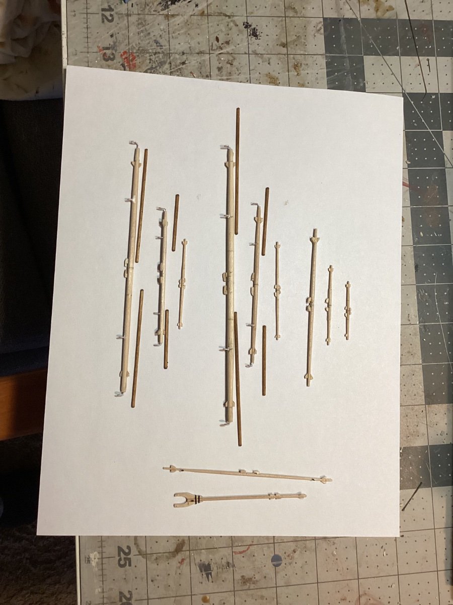
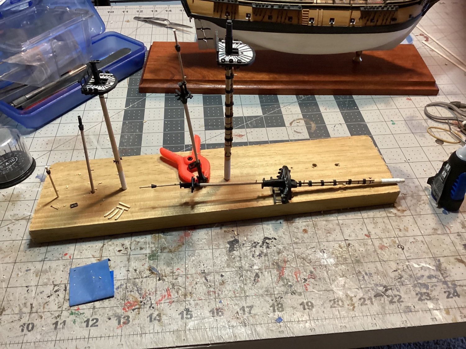
Topmasts and Top Gallant Masts I’ve been fabricating the upper masts per the plans. The kit provides mast caps for the lower masts but not the upper ones so I ordered some small ones from BlueJacket. I had some trouble getting the crosstrees right until I figured out that is was best to assemble them on the masts to ensure a proper fit around the different sections of the masts. The Fore and main Top and Top Gallant masts are done (just dry fitted to the lower masts) and the Mizzen is ready for assembly. I’ve fitted brass pins in the masts where the yards will go: Next up will be the yards.

- 142 replies
-
- 6
-
-
- alfred
- solid hull
- (and 2 more)
-
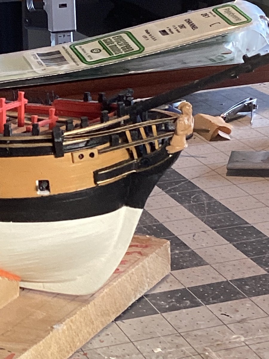
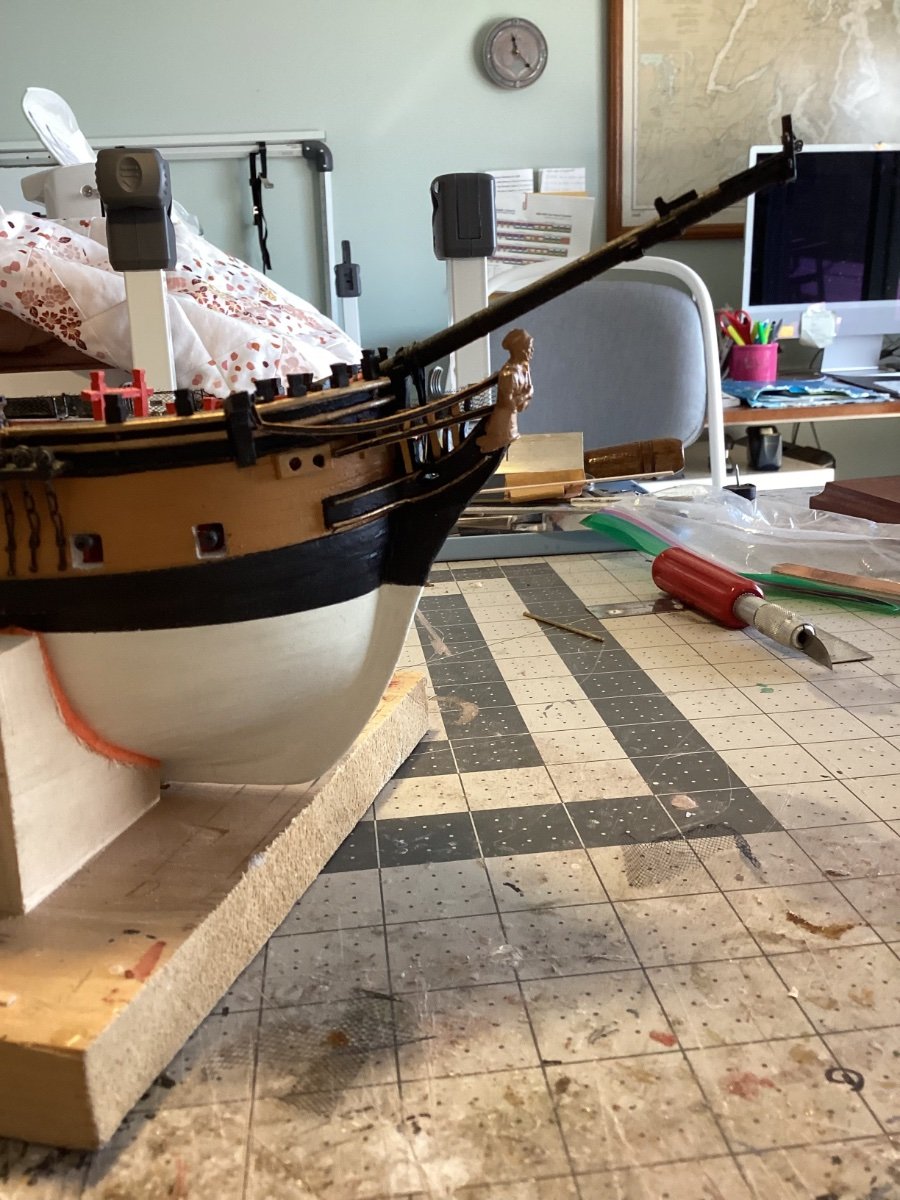
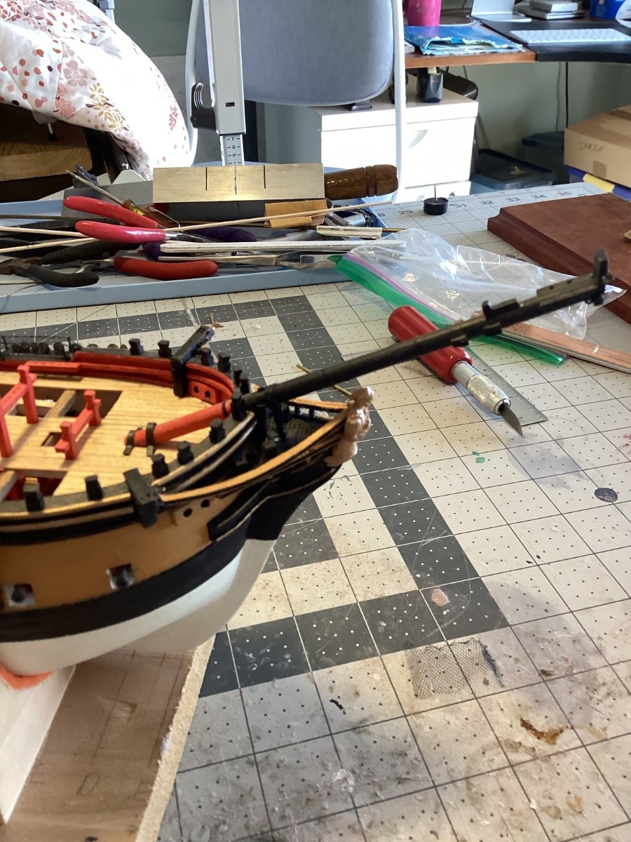
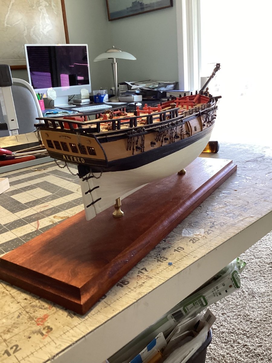
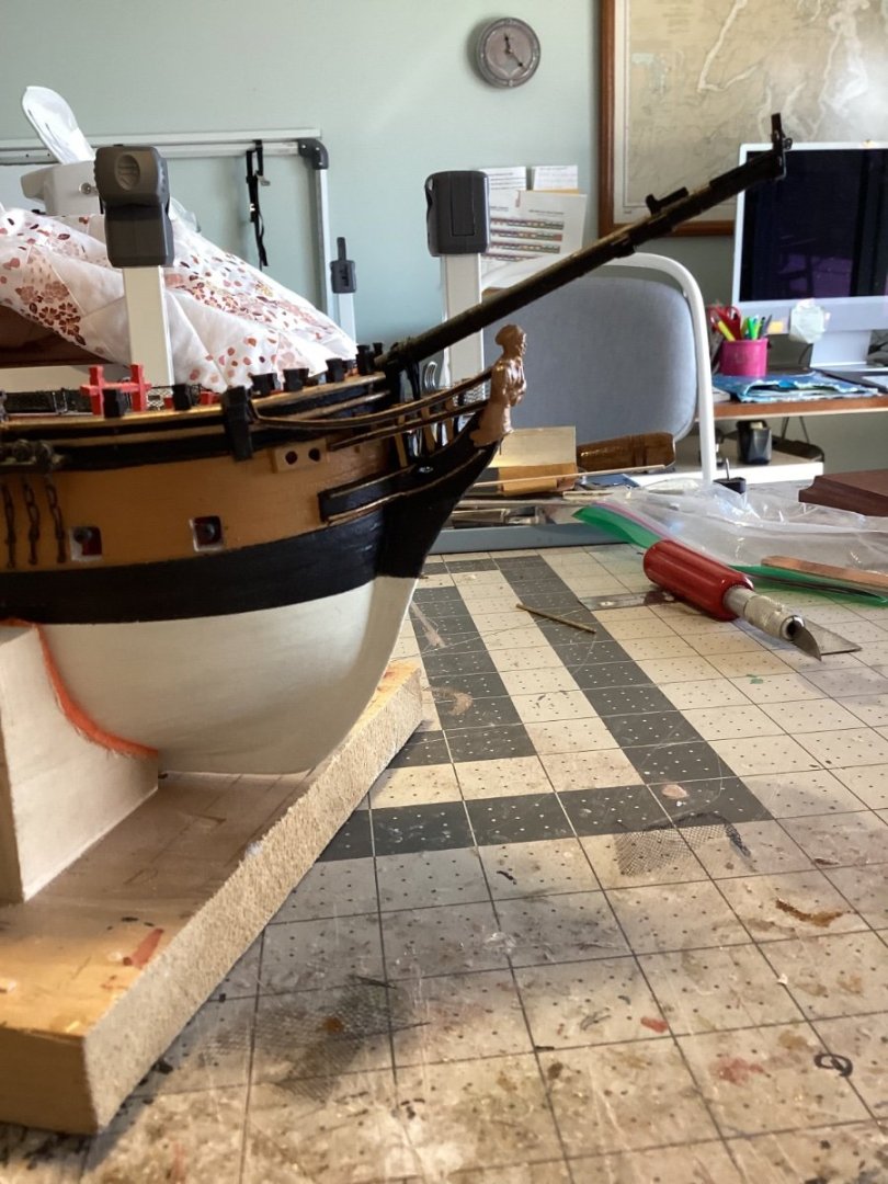
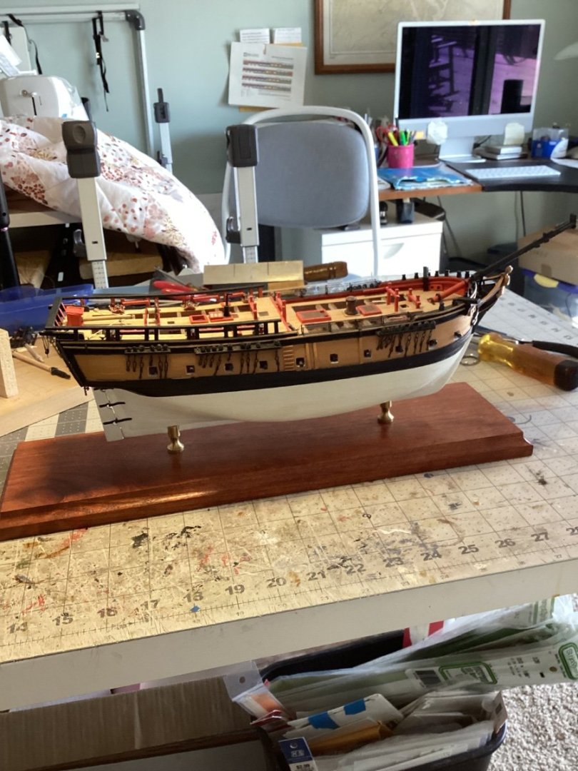
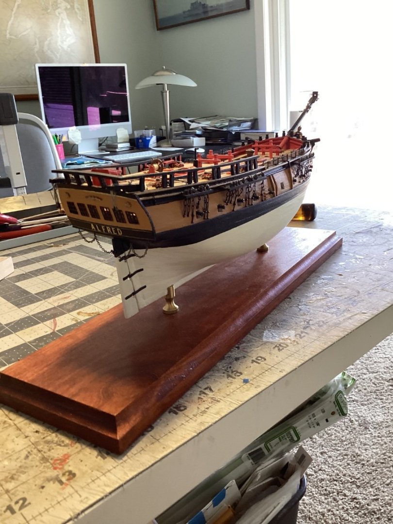
Back to the Shipyard So, after a six month diversion into the world of radio control while building the SEGUIN, followed by an extended road trip out to the West Coast, it’s finally time to get going again with the ALFRED. Before starting on the masting and rigging I wanted to do 2 things. First up was fixing the upper head rails. My first attempt left them pretty straight without any of the “swoop” normally seen on the headrails of period ships (swoop being my term for vertical curvature): So I removed them (the lower headrails had to be left alone since they conform to the outer edge of the PE grating) and replaced them with the same mix of Brittania metal from BlueJacket faced with plastic channel pieces from Stripstyrene; I’m much happier with the re-do: The other thing I wanted to do was to mount the model on its pedestals and display board because it would be a real nightmare trying to do it with all the masts and rigging in place. Since the masting and rigging should not require placing any serious pressure on the hull I think now is the time to do it: Now I can put the hull on the shelf and work on the upper masts.


- 142 replies
-
- 12
-
-
- alfred
- solid hull
- (and 2 more)
-
Thanks!
-
Hi Tom, I just came across your log and have spent a lot of time looking at the rigging. I'm getting ready to start masting and rigging my ALFRED from BlueJacket and your techniques and rigging sequence have caused me to rethink my plans. Your explanations are lucid and your photos are sharp. Thanks for taking the time to post. Quick question: You have referred to "Ultra rope" as great stuff. Could you point me to the manufacturer or website - I have had no luck on my searches. Thanks and keep up the good work.
-
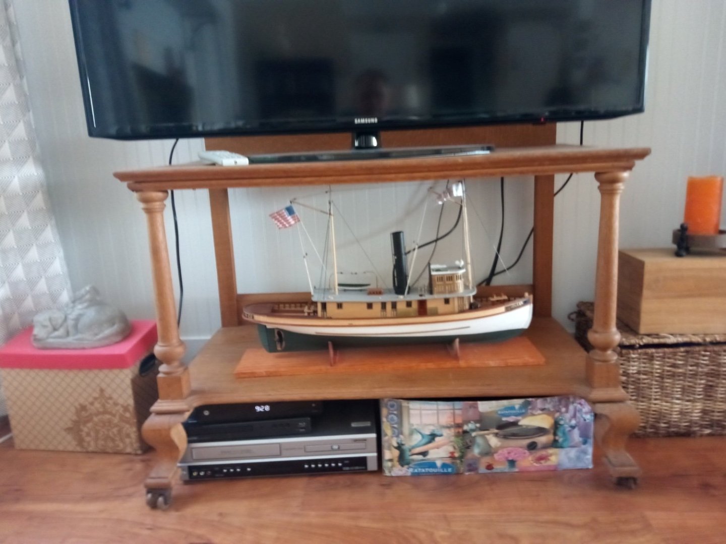
Rod, I just got back from a long road trip so I missed the finish to this build. Great job!!! I had no idea this kit was so detailed, and complicated, but you really did her justice. Maybe you could bring all of your model ship building skills to bear and make your TV cabinet look like the bow of a planked boat!
- 58 replies
-
- 1
-
-
- Robert E Lee
- Amati
- (and 4 more)
-
Wonderful work! Very clean and neat. Are you going to build or buy the case?
- 166 replies
-
- 4
-
-
- Maine
- BlueJacket Shipcrafters
- (and 1 more)
-
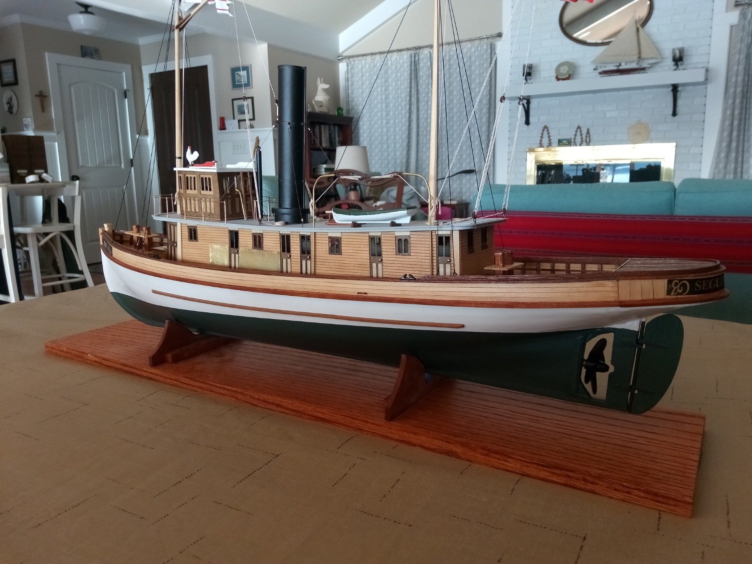
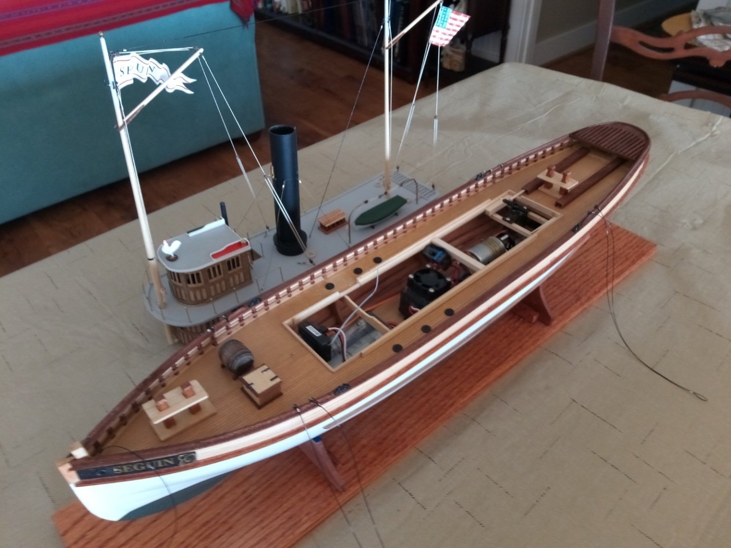
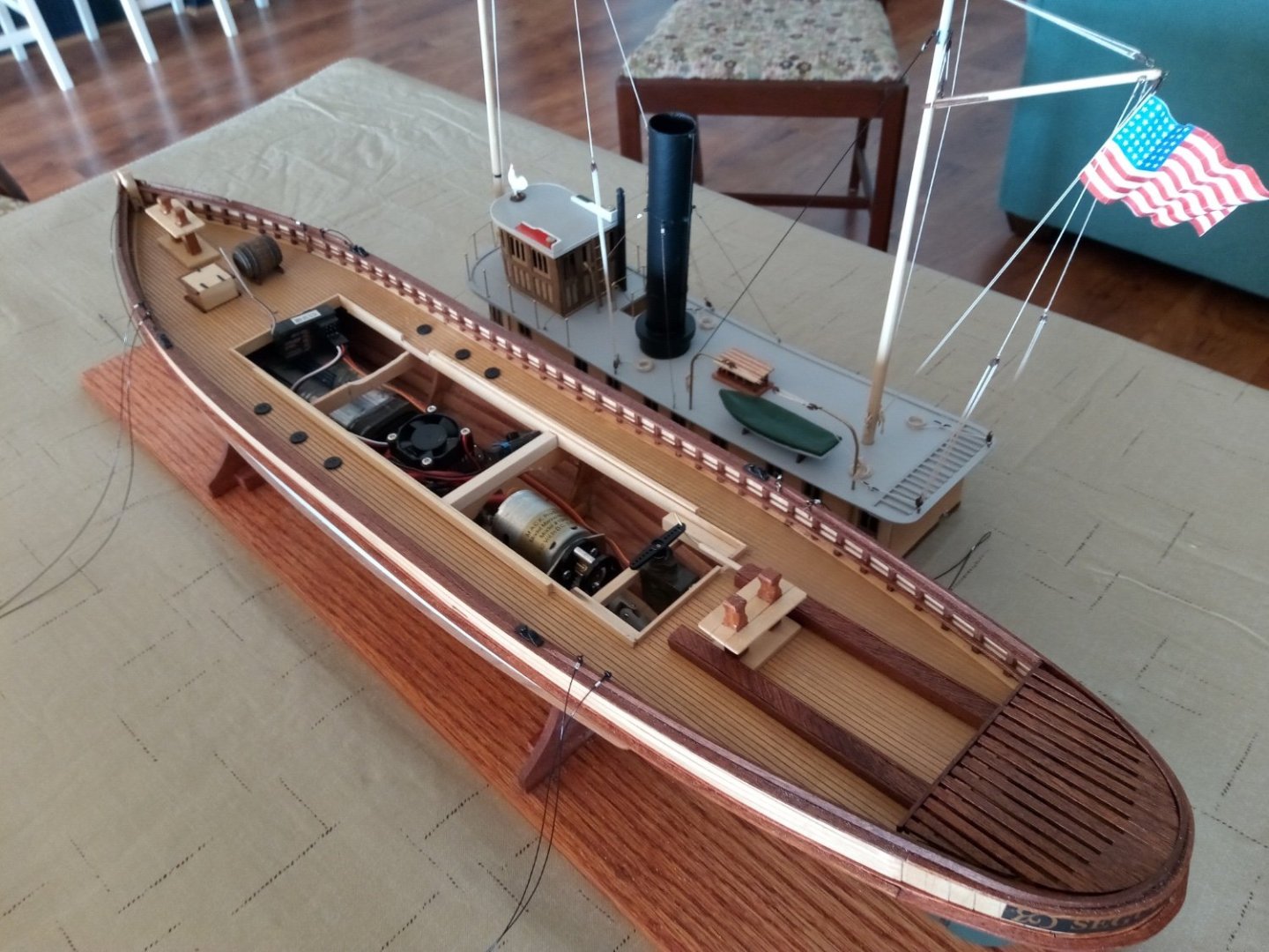
Thanks for all the likes and compliments! It's a nice kit. Ian, the stack is not connected to the interior but all 20 of the windows and doors in the deckhouse were left unglazed so that the heat from the ESC and motor could vent. I think (hope) I'll be alright.
- 72 replies
-
- 1
-
-
- Seguin
- BlueJacket Shipcrafters
- (and 2 more)
-
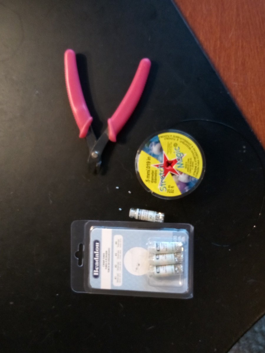
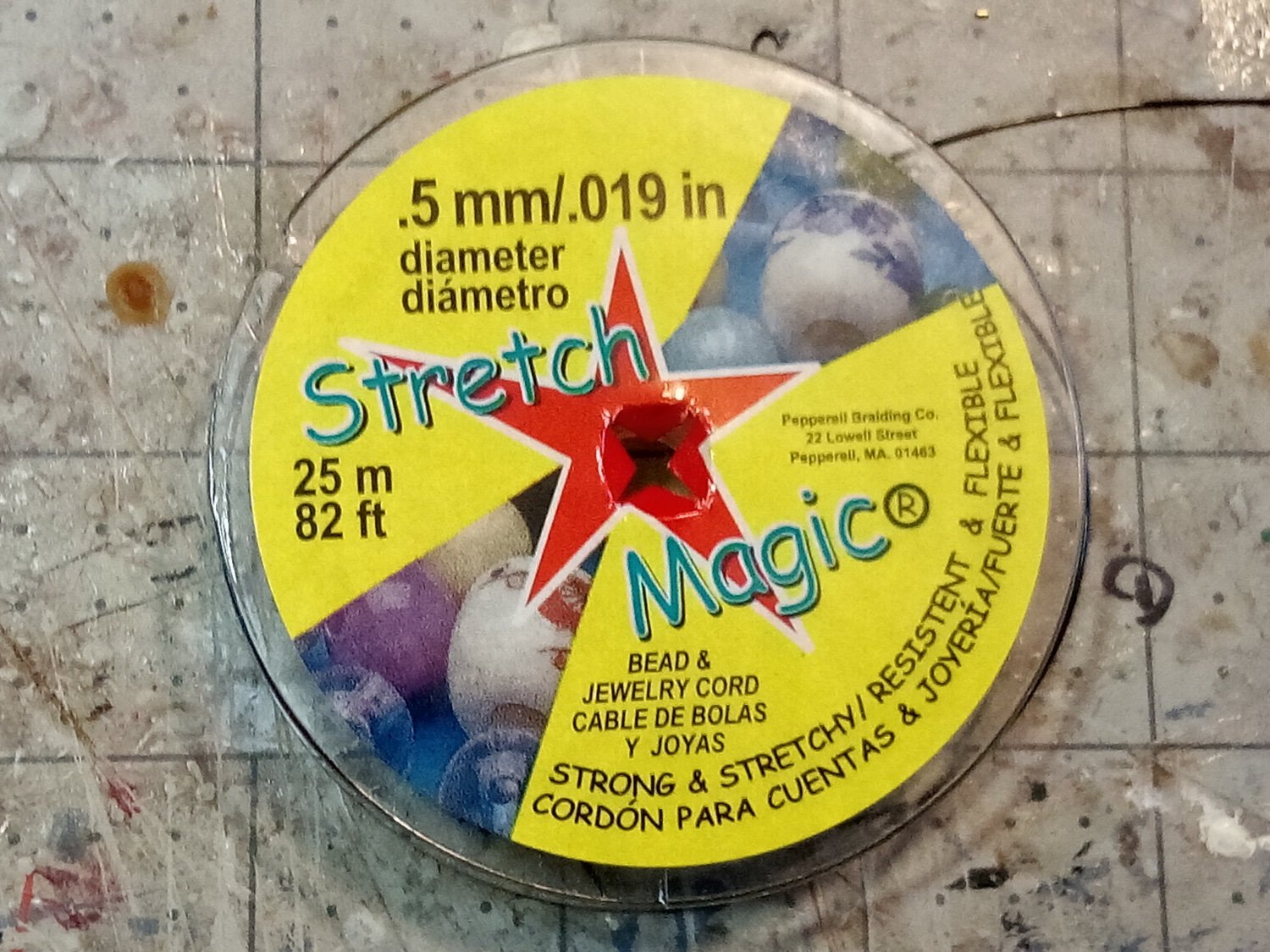
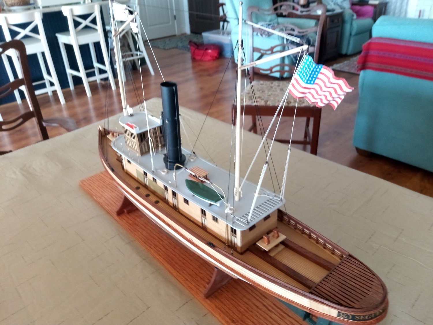
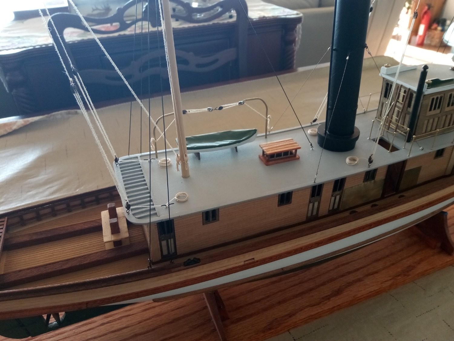
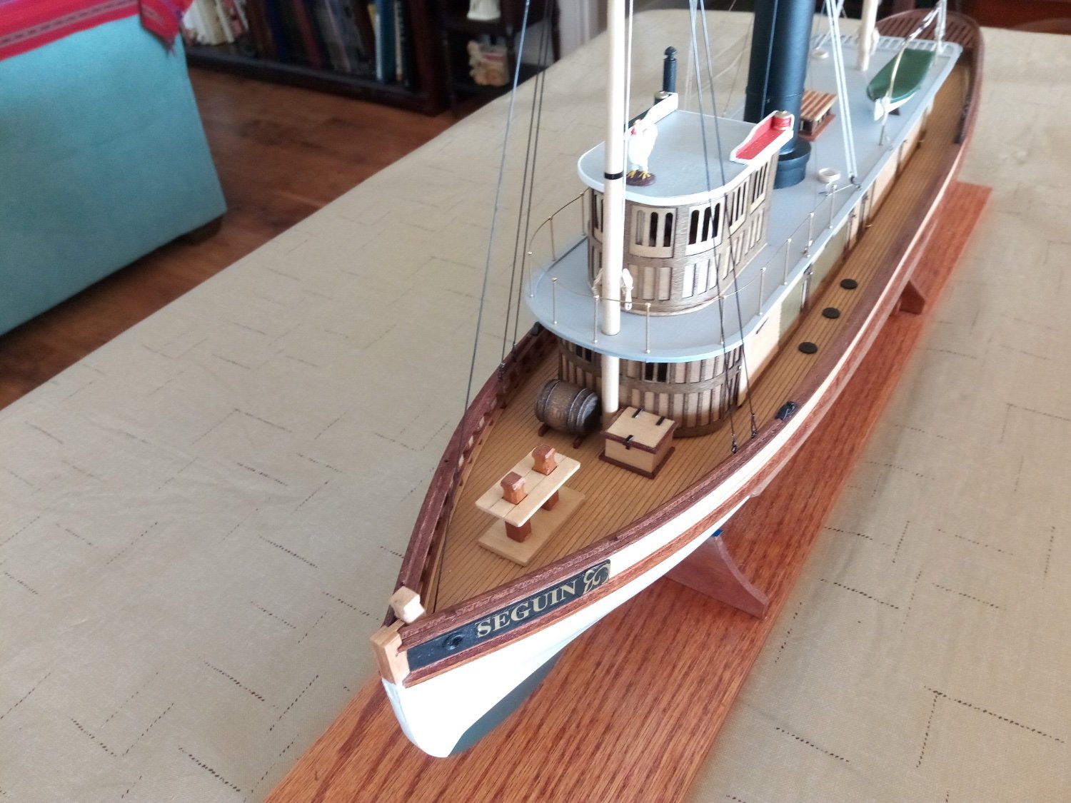
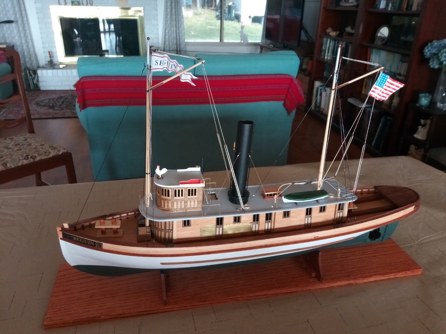
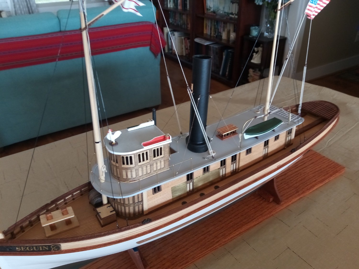
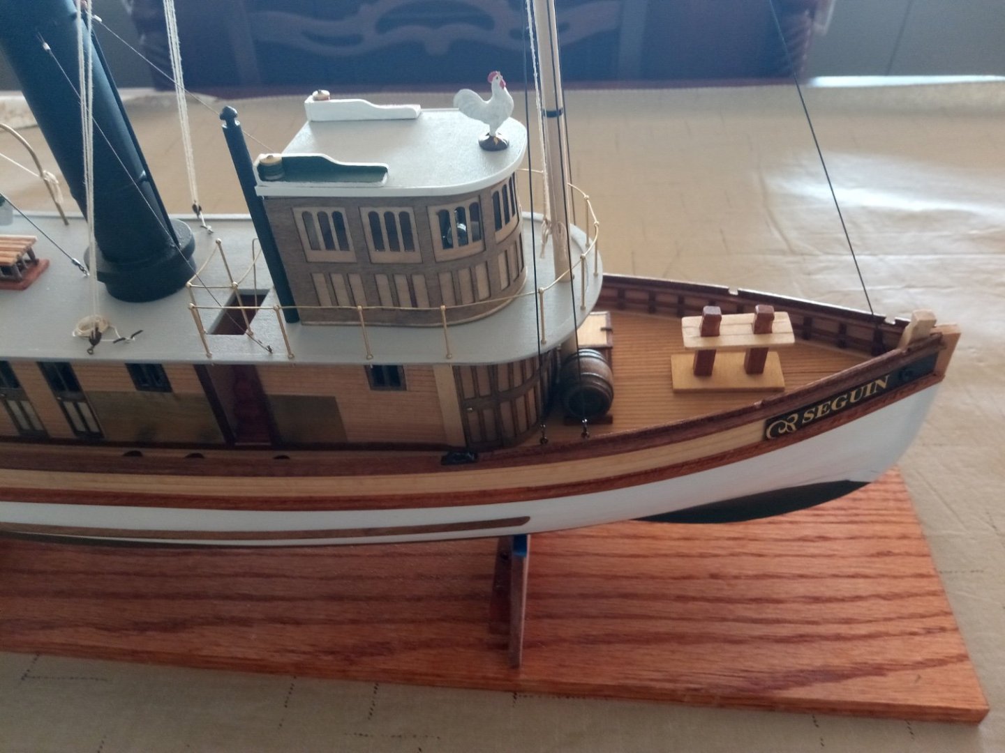
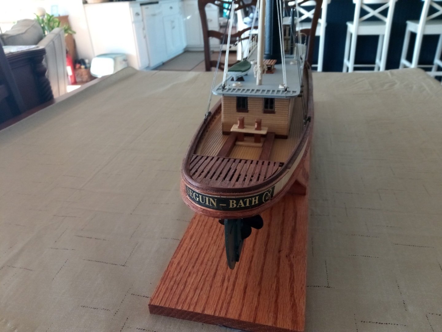
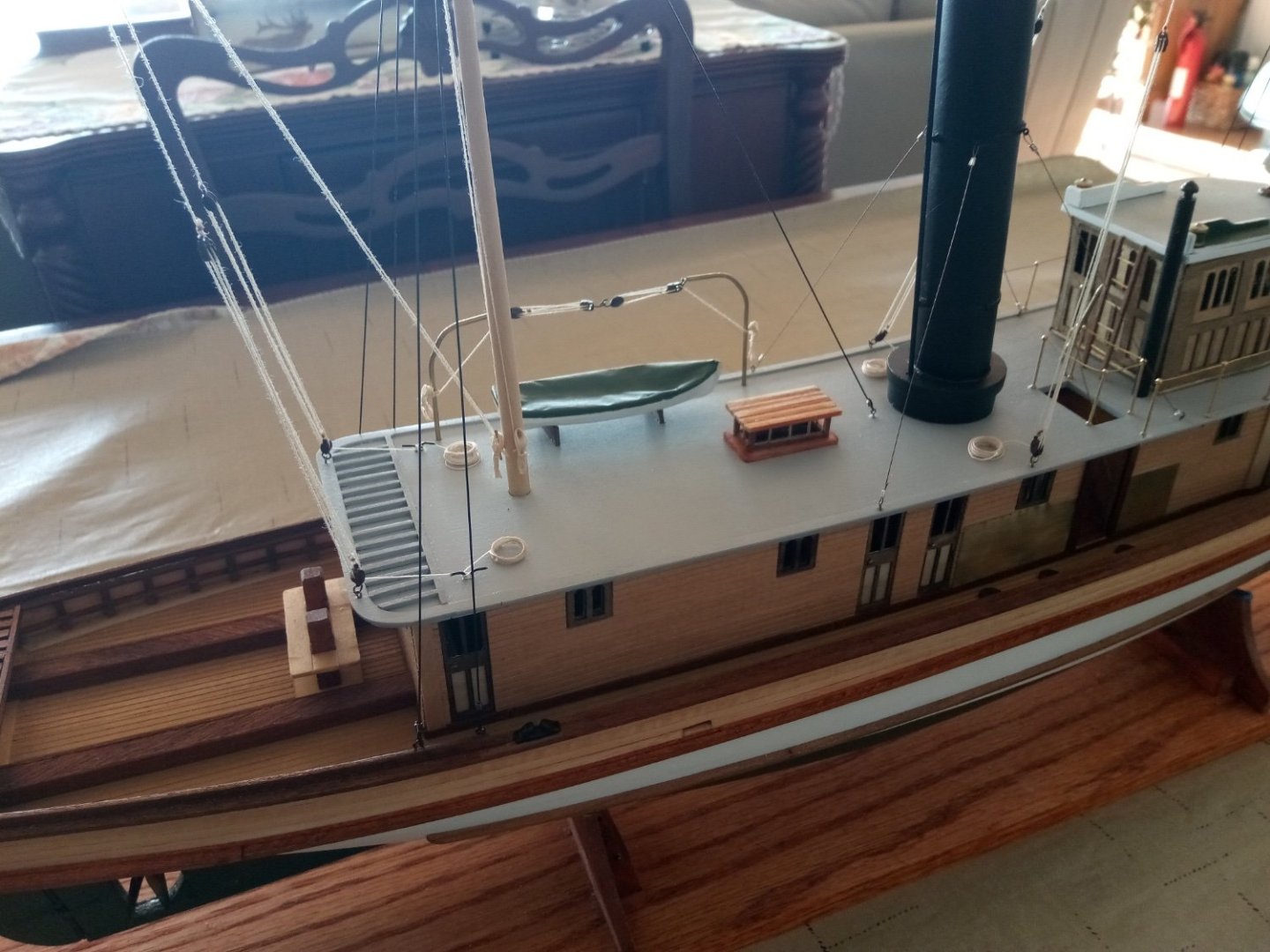
21. Ship’s Boat and Final Rigging The Boat The instructions call for carving a provided block of wood into a boat shape -that's beyond my skills so I ordered a 3 3/16" britannia boat from blue jacket and covered the top with tracing paper to simulate a canvas covering. Standing Rigging For the shrouds and stays I followed the recommendation in the instruction book for the RC option and used black stretch cord (.5mm) that I bought online. To secure them I used .015 inch crimping tubes. Previous build logs, as confirmed by the plans, reported that the after boat davit is completely blocked by the shrouds on the port side of the aft mast so I moved both davits 1/2” forward. Several build logs reported a problem with the shrouds impinging on the deck house roof. I found that if I anchored them on the inboard side of the cap rail that there was no problem. The stretch cords, set to be about 1 inch short of their pre-stretched final length, hold the deckhouse firmly in place but are easy to lift off of the hooks on the mast so the house can be removed. Running Rigging and the flags The model comes with a gaff boom on each mast. I assumed they were there as part of an emergency “get home” sailing rig. If so, the rigging on the plans did not make much sense to me so I copied the gaff rigging used on my model of the USS Olympia (built at the same time as the Seguin) and added double blocks to the gaff vangs and changed the rigging of the gaffs themselves. The paper flags are from the kit. I rubber-cemented a piece of aluminum foil onto the back of one half of the flag, leaving a border around it for paper to paper gluing. When dry I placed the halyard in the fold crease and then folded and glued the flag halves together. Two different size dowels were used to impart alternating curved folds. Although the dowels could just as well be used to make the flags hang limply I wanted the Seguin to look as if she is headed down the Kennebec River under a full head of steam to pick up a schooner to tow into Bath for an extortionate fee. The only thing left to do now is to design and fabricate a launch/recovery/carrying cradle, probably from PVC piping and then conduct the maiden voyage, but that will have to wait until Nov when we get back from a road trip out to the West Coast.


- 72 replies
-
- 15
-

-
-
- Seguin
- BlueJacket Shipcrafters
- (and 2 more)
-
That is one sharp-looking model! Your "chrome" stanchions" look great, I'll have to remember that trick.