schooner
-
Posts
741 -
Joined
-
Last visited
Content Type
Profiles
Forums
Gallery
Events
Everything posted by schooner
-
 I've never heard of "pre-made seizings." They look really good - could you take a photo of how you make them when you move on to the next set of deadeyes?
- 422 replies
-
- 2
-

-
- Vanguard Models
- Sphinx
- (and 1 more)
-
Very Nice!
-
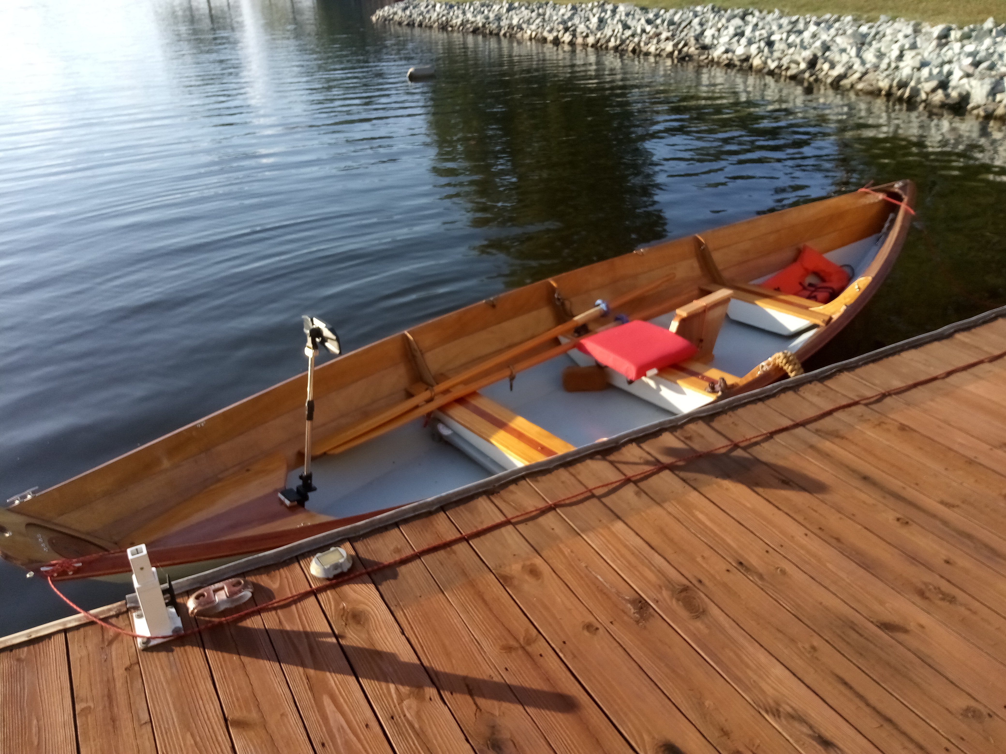
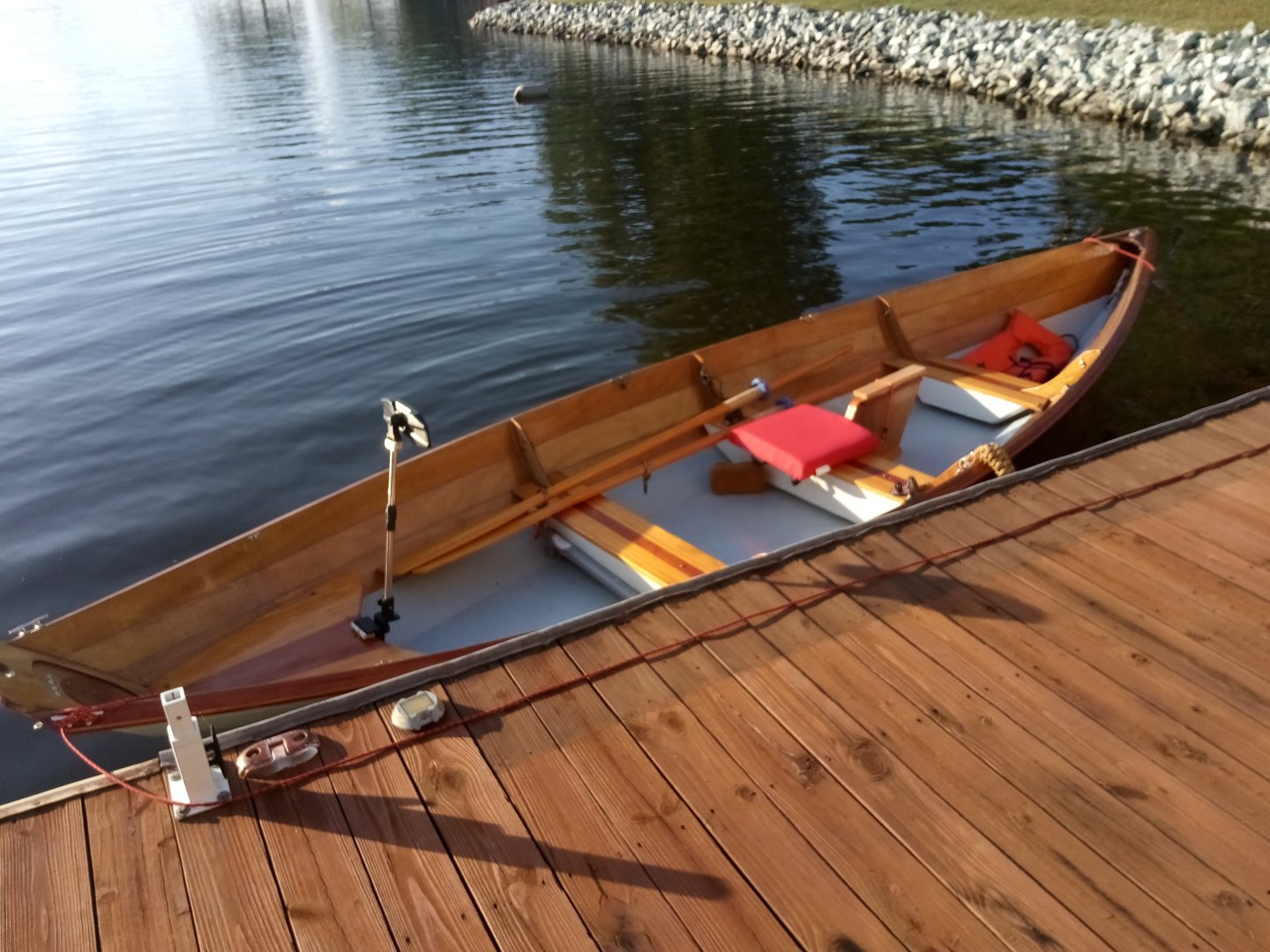
You are half right, it's a CLC New England Dory. Rows like a dream.
- 72 replies
-
- 1
-
-
- Seguin
- BlueJacket Shipcrafters
- (and 2 more)
-
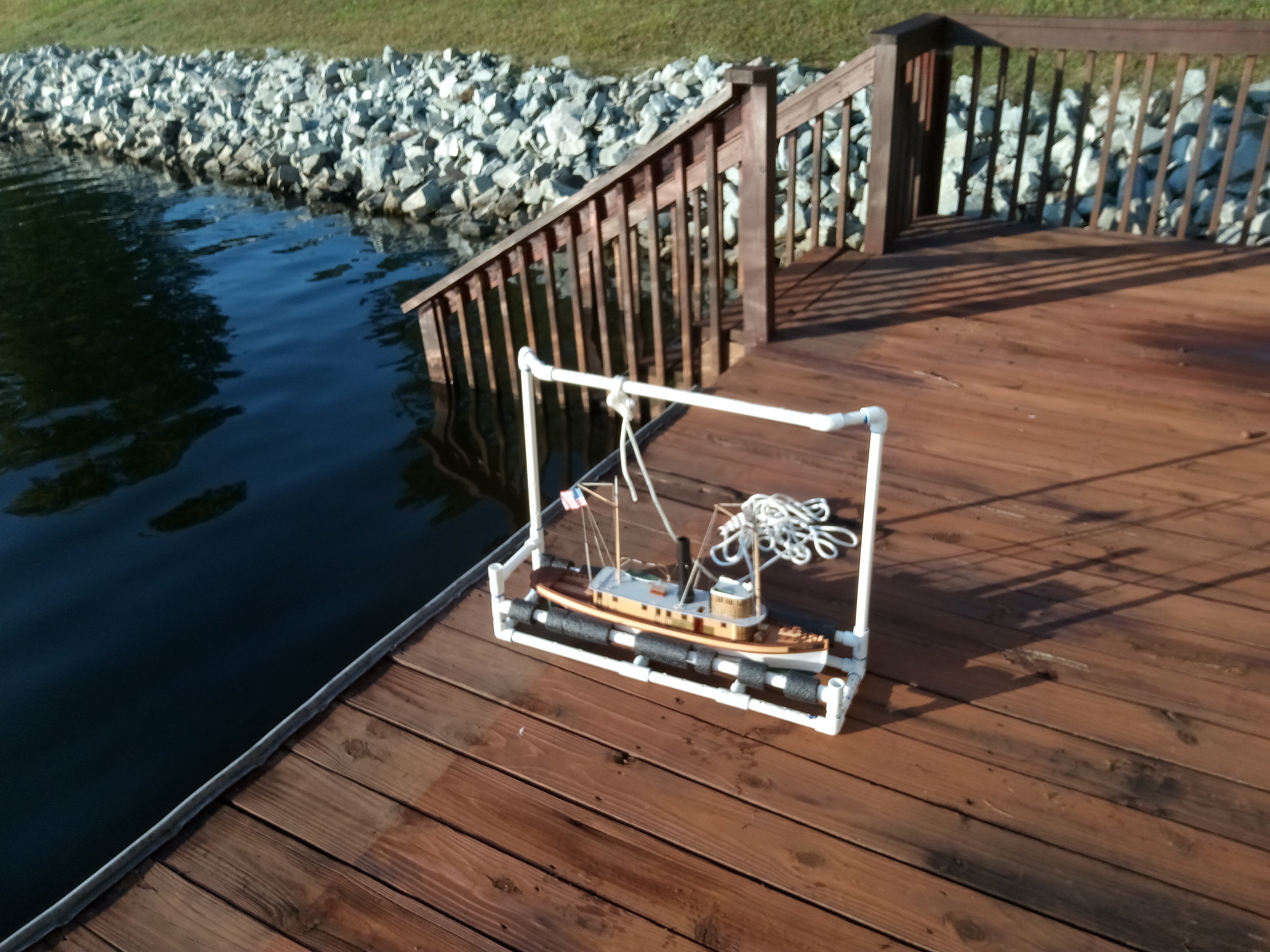
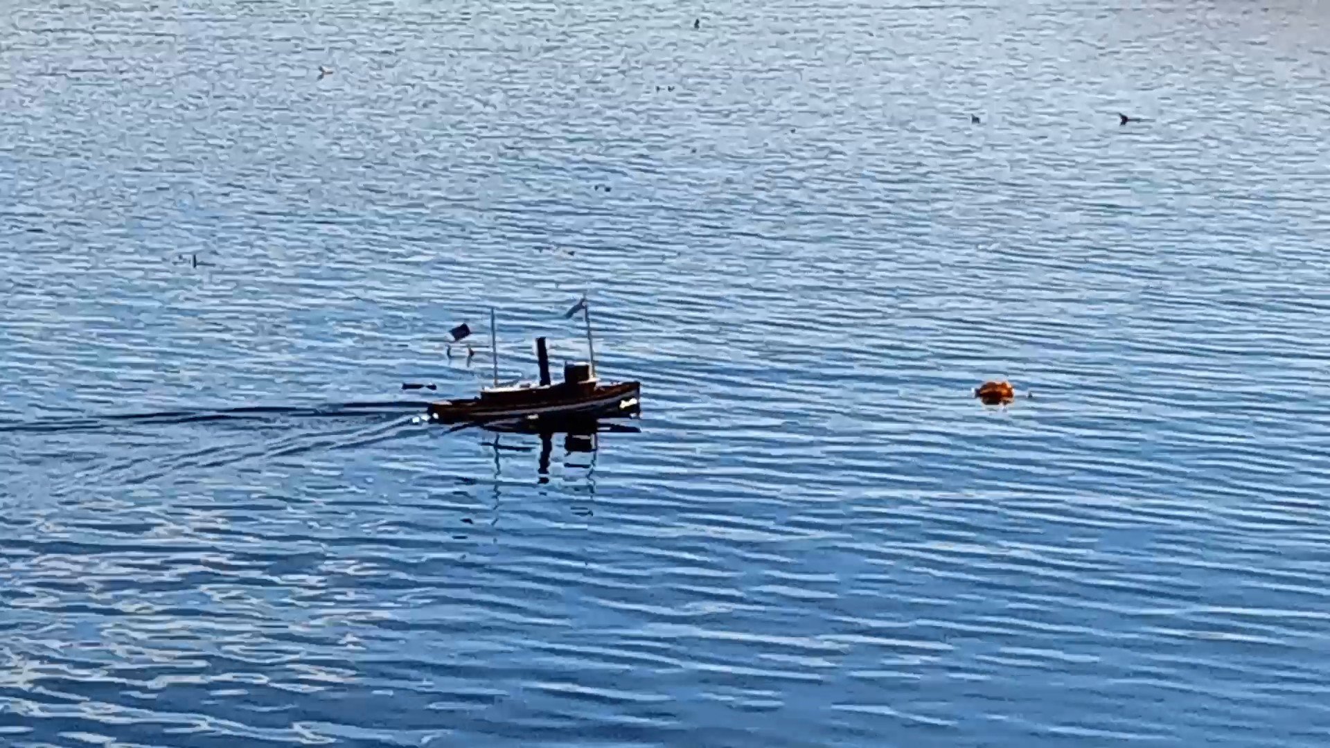
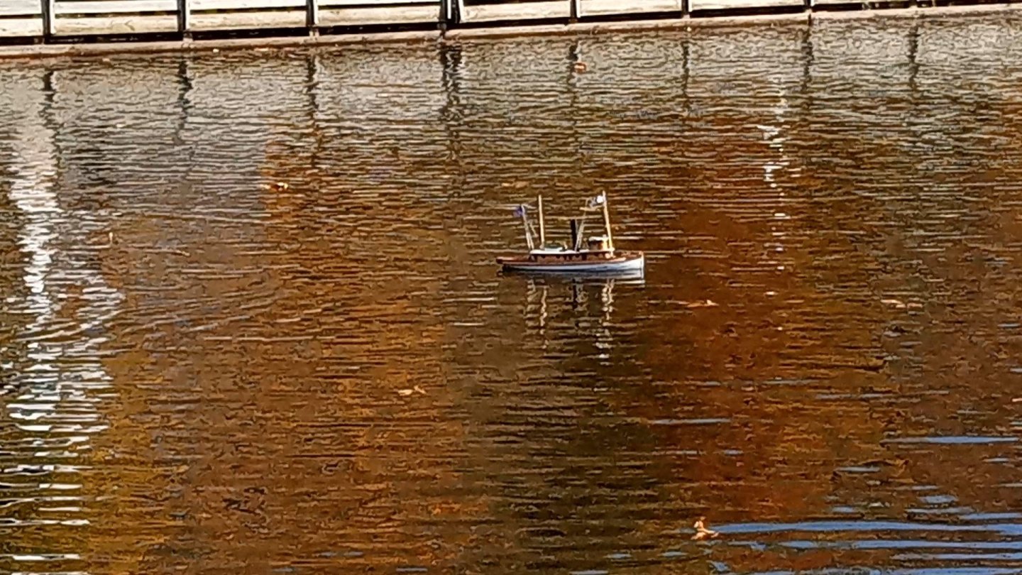
Seatrials…. The PVC launching/recovery and carrying cradle has worked well: I think the single most important item for operating a RC model on anything bigger than a swimming pool or small pond is the R3 (rescue recovery rowboat) The model runs pretty fast - it throws a nice wake, anything faster and I would worry about its’ stability when turning. It turns OK but I wish the rudder servo had a wider range (or maybe it is the controller/transmitter). I’m only getting about 10 degrees each direction so its’ turning arcs are a little wide. I made some videos of the model running around but I can’t figure out how to get them off my phone onto my computer (file size is too big to email).


- 72 replies
-
- 7
-
-
- Seguin
- BlueJacket Shipcrafters
- (and 2 more)
-
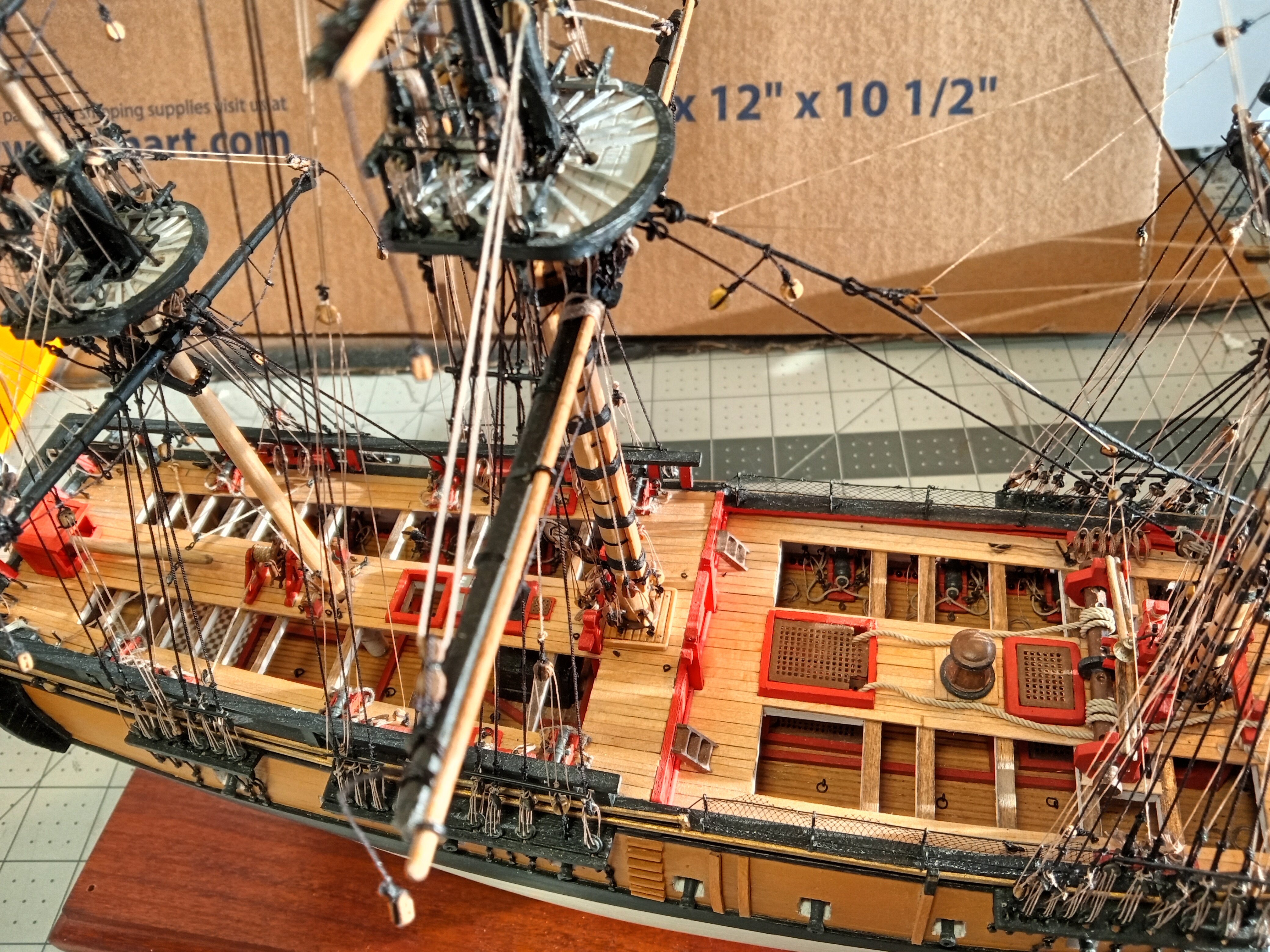
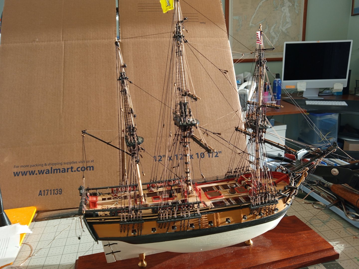
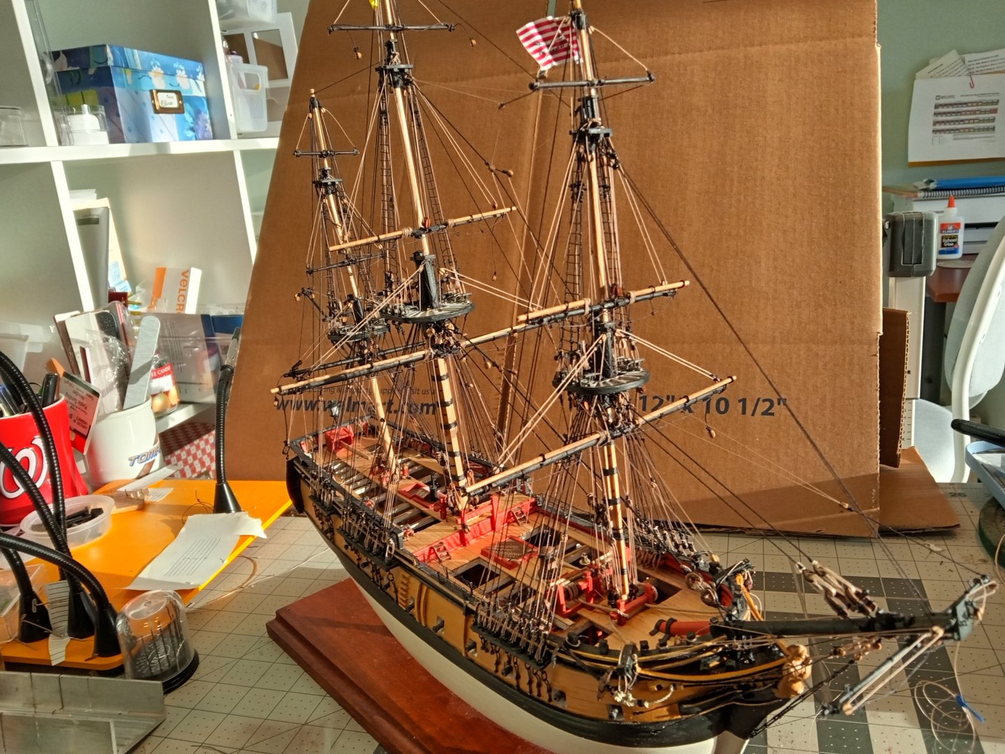
Just about done with the rigging All the rigging directly associated with the masts (halyards, lifts, jeers, shrouds, stays, etc) has been added along with a couple of the yard braces. The only things left to rig at this point are the rest of the yard braces, the jib boom and its’ rigging and the ratlines on the lower shrouds. The end is in sight.

- 142 replies
-
- 9
-
-
- alfred
- solid hull
- (and 2 more)
-
Roel, One idea for launching and recovering is something I saw here on the scratch logs for a fully rigged RC sailing frigate that looked about as long as your model (although much taller obviously). You can imagine how hard it would be to handle a fully rigged ship. Unfortunately I can't find the build log right now. The builder built a wheeled cart with 2 wheels on one end and handles on the other, sort of like a wheelbarrow. something like that would allow you to launch and recover your model fully assembled. The cart is pushed into the water until the model floats free and when done the model is just run back onto the cart. If you look around for sites dealing with RC sailing models you should find something similar to what I'm describing. Keep up the good work, Tim
-
Thanks, that's what I needed to know.
-
I just discovered this build log, this is the best scratch detailing work that I have ever seen! Anywhere! One question - how do you launch and recover this model? Do you use a cart that you wheel into the water? Do you have a cradle? Do you just pick it up in your arms and wade in and out of the water? Please keep up the good (and detailed) work.
-
This is a very interesting build log - particularly for someone who has not worked with fiberglass. Quick question - after applying the gray Bondo did you have any trouble avoiding sanding through the glass layer while smoothing the hull? I really like that you are going thru all the work of making this a 3-prop - should be a fast one on the water.
-
One possible explanation for the small side steps - O'Brian's books mention in several places that when senior (i.e. rotund) officers or civilian (i.e. landlubber)VIP's came aboard sideboys would hold manropes on each side of the steps to help the visitor negotiate the steps so maybe that is what the small ones are for.
- 16 replies
-
- 1
-

-
- constitution
- revell
- (and 1 more)
-
Come to think of it, I've never noticed netting in that area either but that mesh is handy for applying to the aft railings on the fighting tops should you decide to add it.
- 301 replies
-
- 5
-
-
-
- Constitution
- Bluejacket Shipcrafters
- (and 1 more)
-
Most of the big craft stores sell black netting like in the above photos, people use it in floral arrangements so it's probably in that part of the store.
- 301 replies
-
- 4
-
-
-
- Constitution
- Bluejacket Shipcrafters
- (and 1 more)
-
Mizzen Rigging With the mast stepped the following are done: Gaff Throat & Peak Halliard and Vangs Cross jack Truss Pendant and Lifts Topsail Tye and Lifts Topgallant Halliard Lower shrouds and backstays Futtock shrouds and staves Rope coils Forestays the "railing" on the top The only rigging left for the Mizzen are the yard braces and the ratlines on the shrouds.

- 142 replies
-
- 4
-
-
- alfred
- solid hull
- (and 2 more)
-
I just use spray primer from the big box hardware stores - it shows any imperfections from shaping the hull that need attention and when you finally get a good smooth primer finish then you know you'll have a hull that looks like steel. As far as the anchor winch, I ended up scratch building one for my Liberty ship using plastic rods and stock, brass tubing and most important of all some old watch gears I found online:
-
Wonderful build!!!! From what you said in one of your early posts this is basically a scratch build. Lovely woodworking!
-
In case you didn't know there is one surviving Victory ship, the SS American Victory, down in Tampa Fl (https://www.americanvictory.org) you can google the ship's name to get some pics that may help and depending where you live you can even tour her, or the similar Liberty ship SS John W. Brown in Baltimore (https://www.ssjohnwbrown.org). The instructions for the current Bluejacket kit might be helpful - it would be worth a call to them to ask, they are very helpful. Interesting photos, looks like someone did a fair amount of the drudgery in shaping the hull for you ... good deal.
-
Nice jig for the ladders!
-
Looks like you are off to a very good start! That is a gorgeous kit that really depends on a good paint job to "be all it can be" and it seems like you nailed it. Keep up the good work.
-
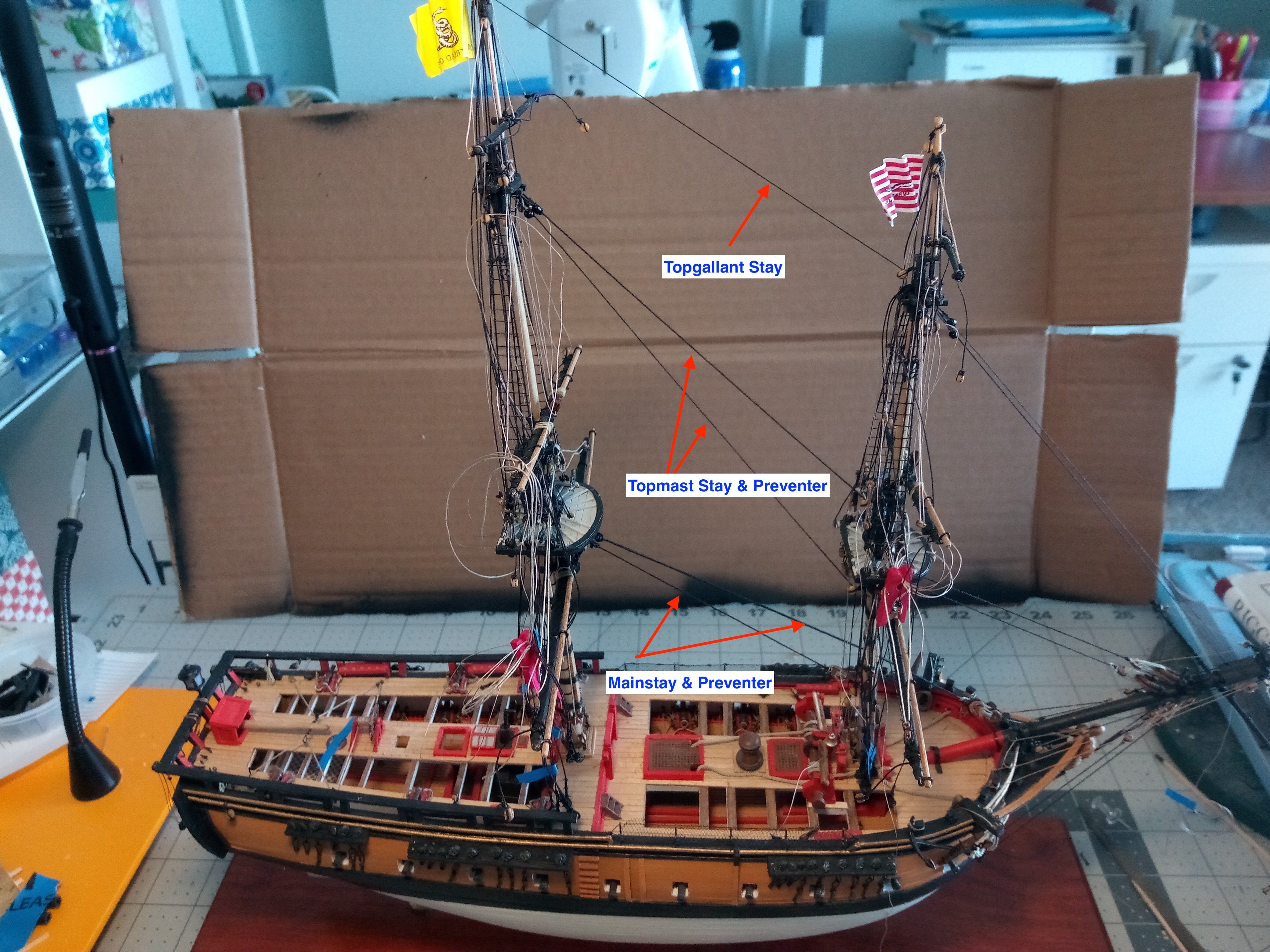
Main mast in place The main mast has been stepped and the forestays are in place: The deadeyes have been attached to the shrouds and backstays and the main yard jeers and truss pendants have been rigged to their tackles around the base of the mast: Next up will be stepping the Mizzen.

- 142 replies
-
- 3
-
-
- alfred
- solid hull
- (and 2 more)
-
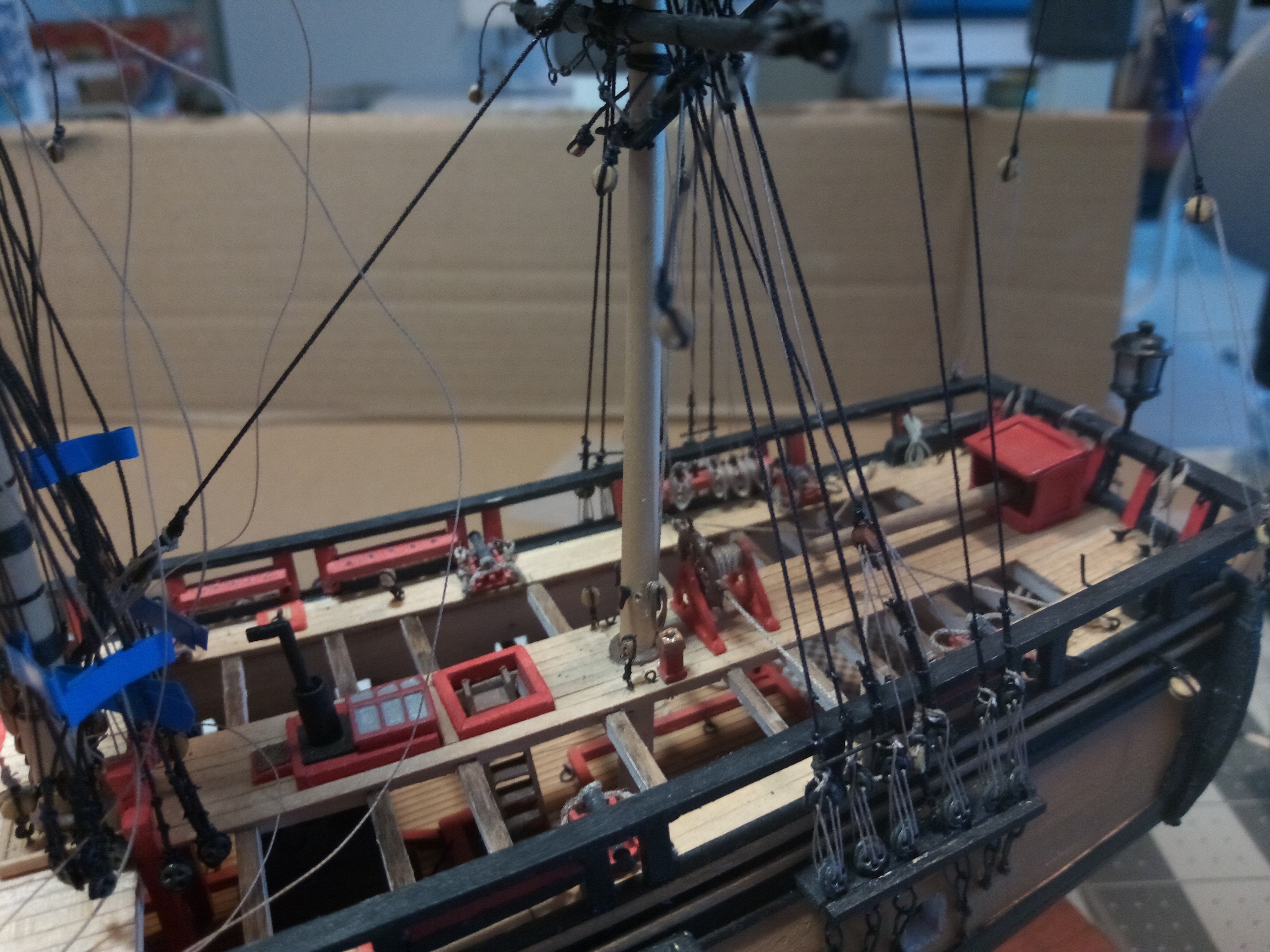
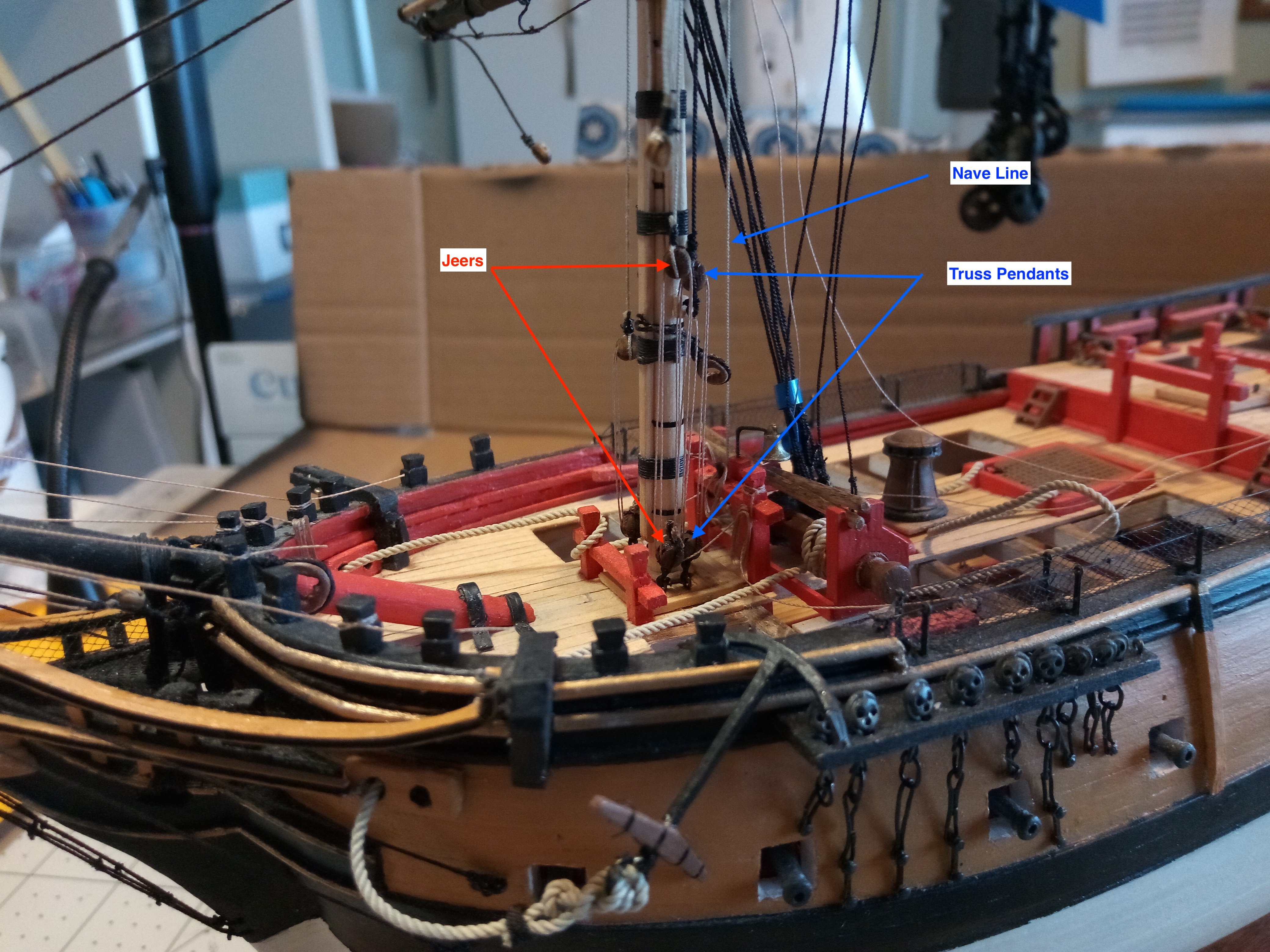
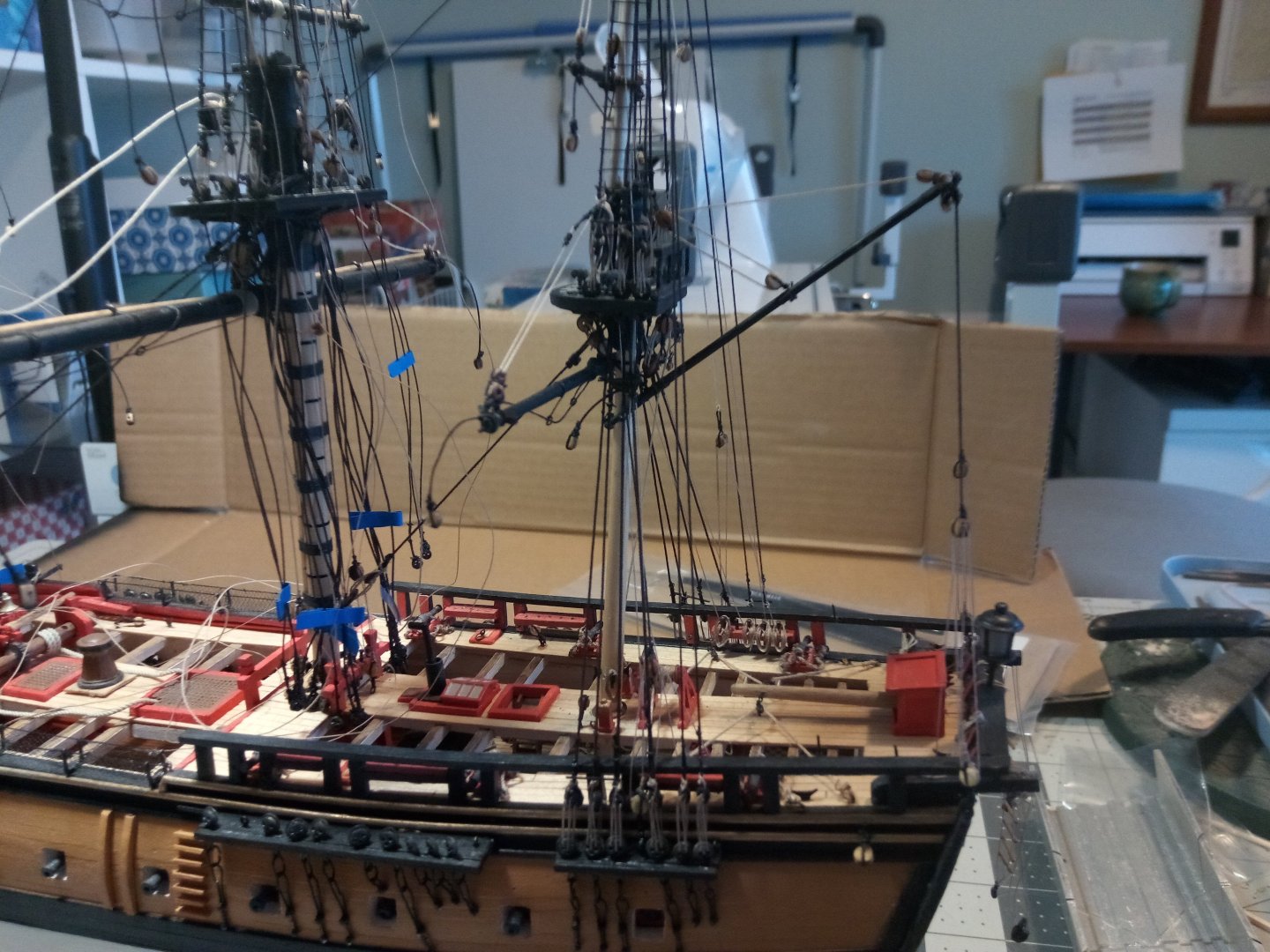
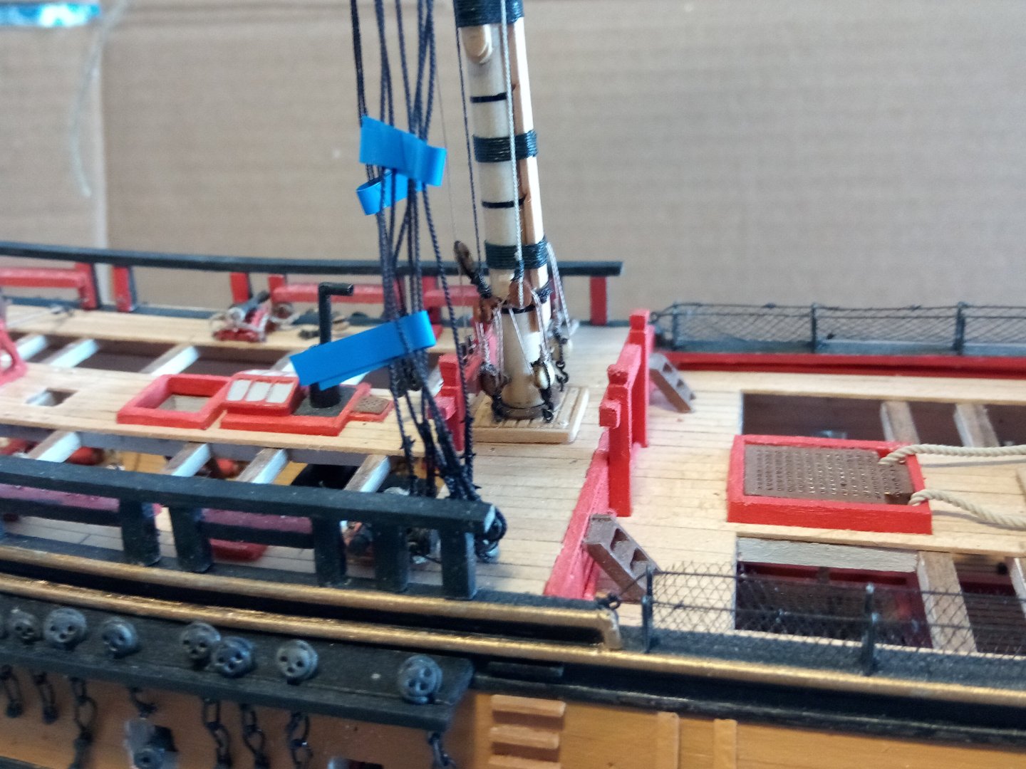
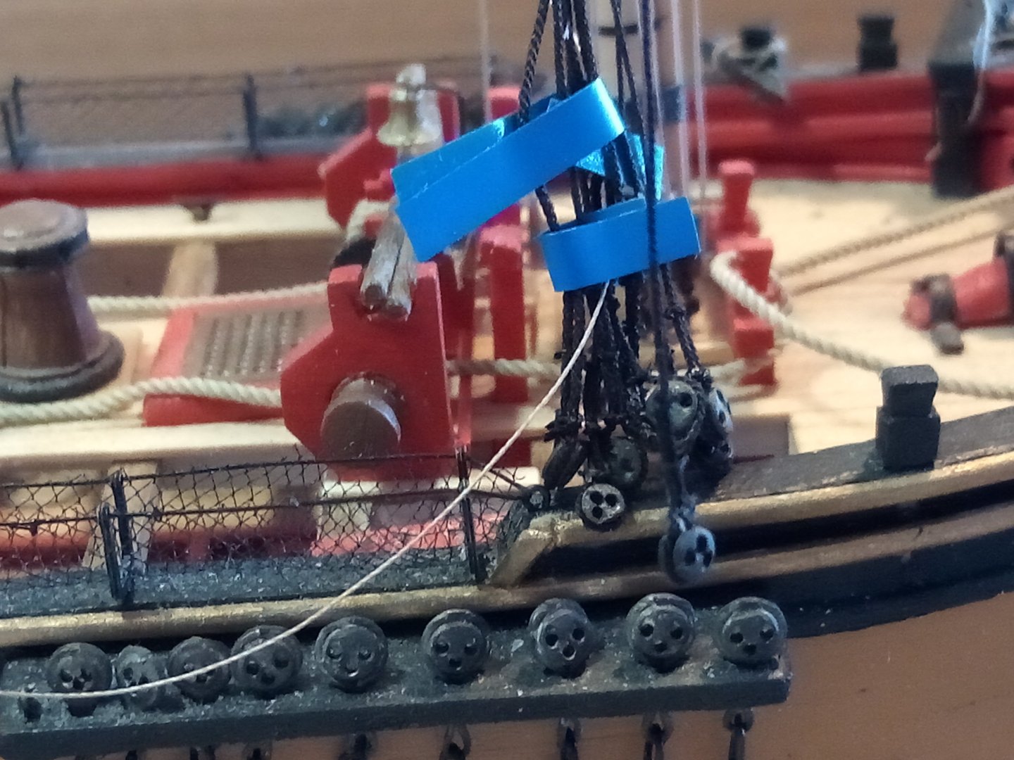
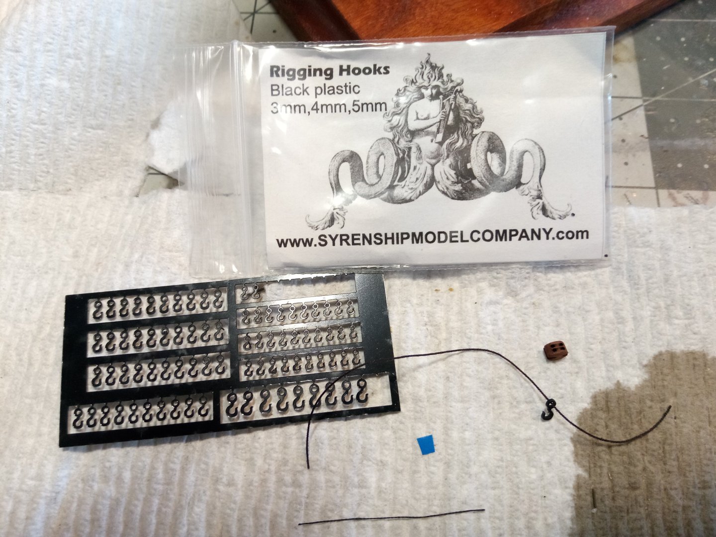
The lines that come down the foremast and are belayed around the mast base are in place. Both the Truss pendants and the Jeers terminate in tackles made up of 2 double blocks (there are 2 more sets on the far side of the mast). The Nave line is just belayed to a pin rack: The upper deadeyes have been added to the shrouds and backstays: Rigging the anchors was made a little easier by the rigging hooks available from the syrenshipmodelcompany.com I used them on the bottom of the rigging tackles shown in the first photo and they should come in very handy for rigging the futtock shrouds under the tops: And here is the anchor in place: I have to make up some rope coils (one of the most tedious tasks for me) and then it will be time to step the main mast.

- 142 replies
-
- 4
-
-
- alfred
- solid hull
- (and 2 more)
-
VERY nice!! I've got the SYREN on my to do list - if mine turns out anywhere near what your's looks like I'll be happy.
-
If I had done those letters your way I would have ended up with them upside down....
- 422 replies
-
- 1
-
-
- Vanguard Models
- Sphinx
- (and 1 more)
-
Great looking model! Your weathering looks realistic but not overdone.
- 97 replies
-
- 2
-
-
- Curtis Wilbur
- I Love Kit
- (and 2 more)
-
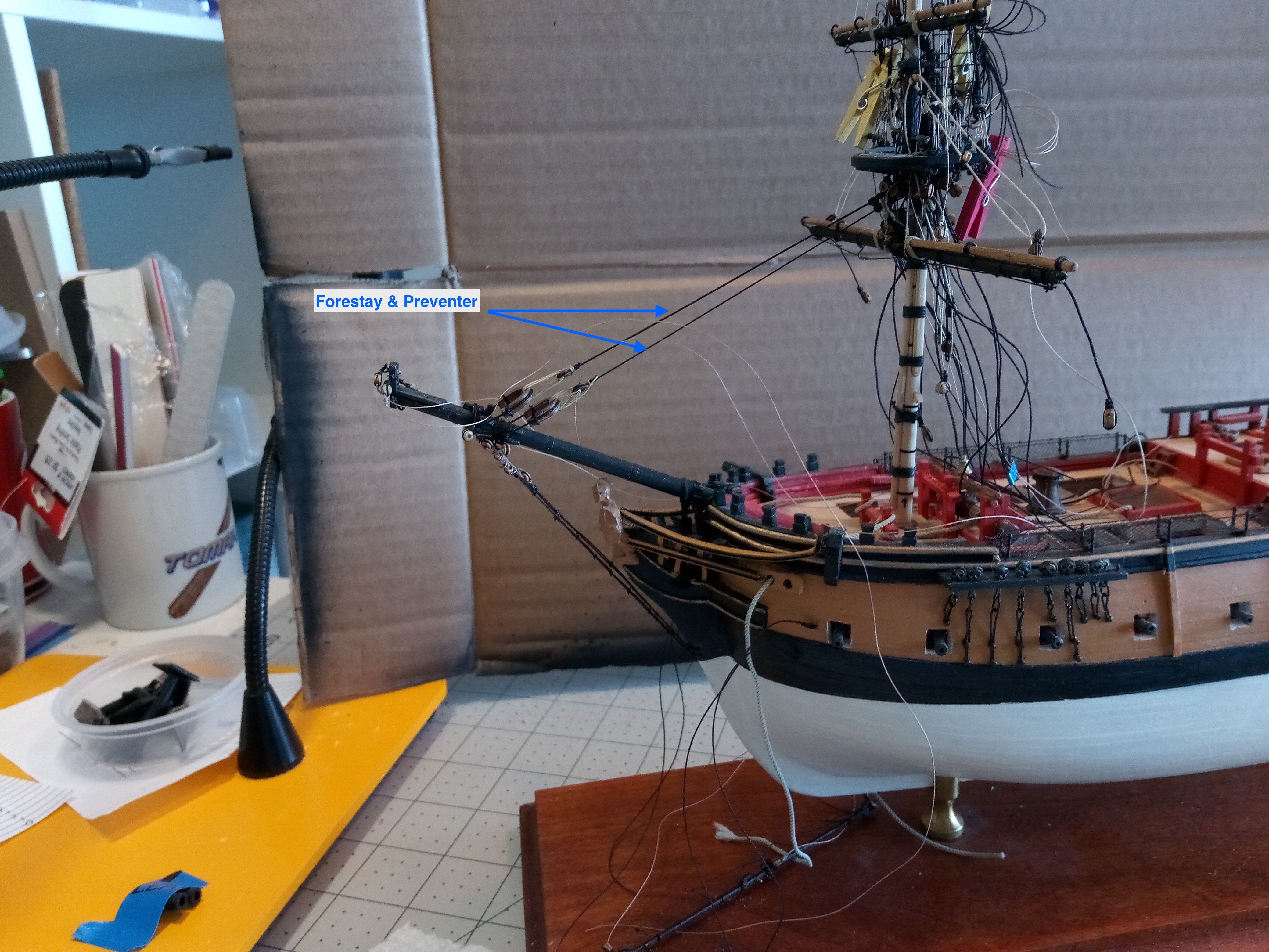
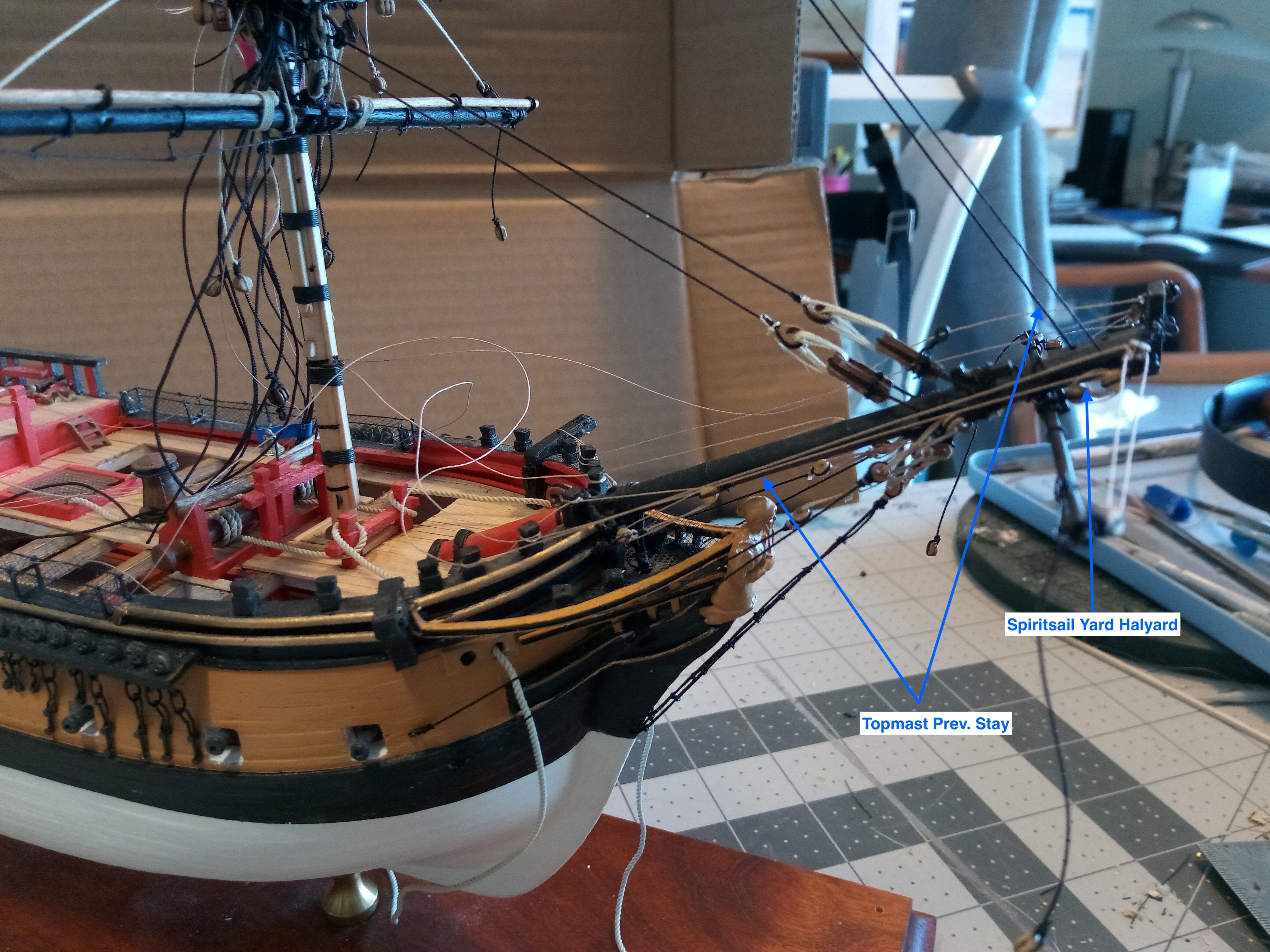
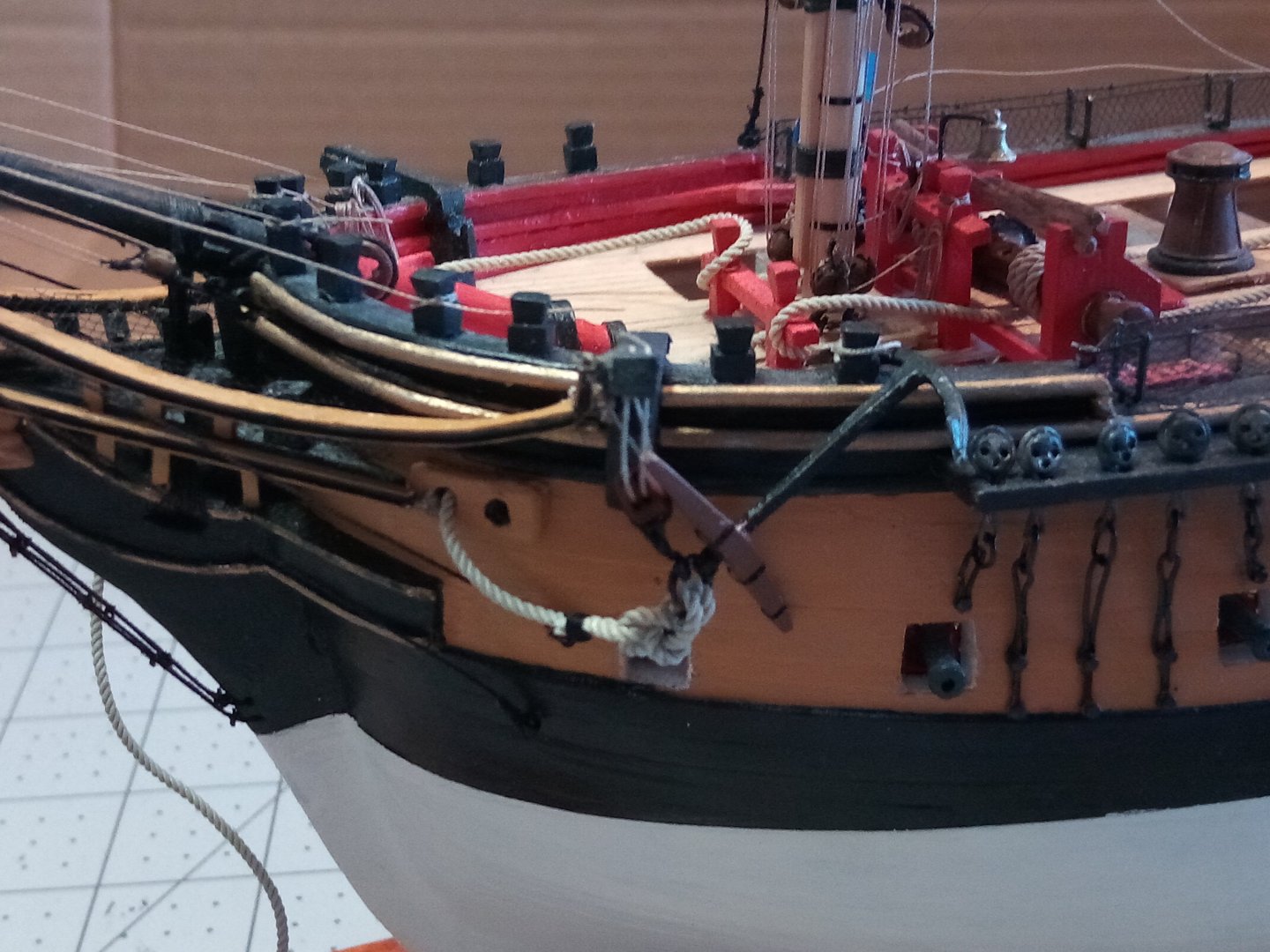
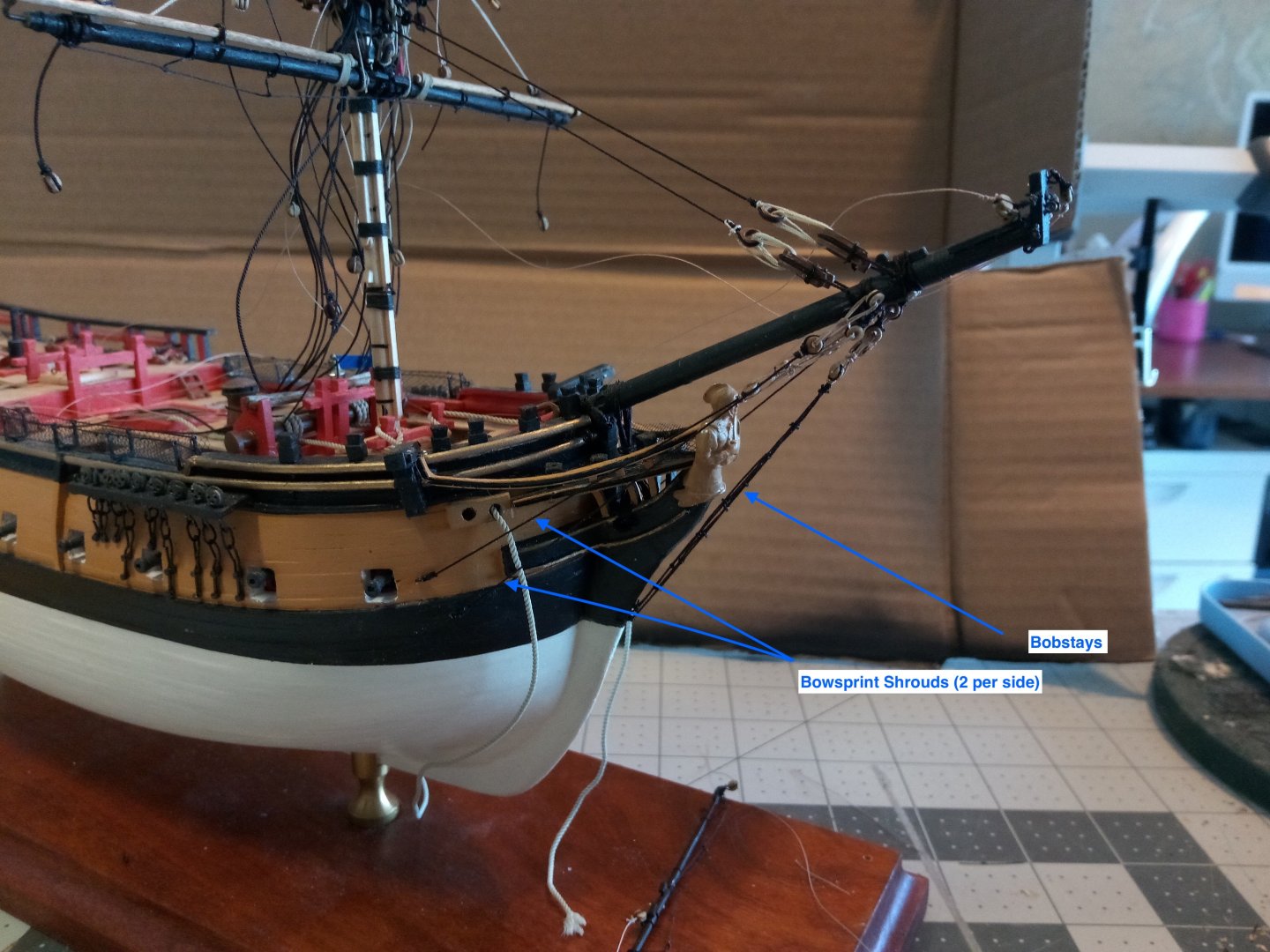
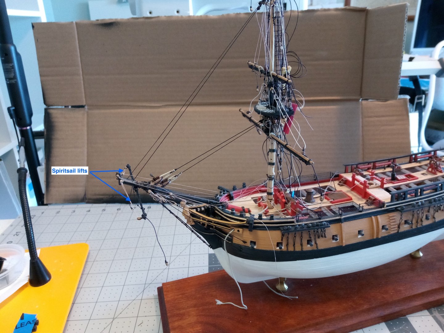
Rigging around the Bowsprit The Spiritsail yard has been rigged with blocks for the lifts and the halyard, eyebolts for the guys and a brass rod to secure it to the underside of the bowsprit: The following photos show the standing and running rigging that has been attached: This is as far as I can go in this area without rigging the jib boom. The boom is very fragile and I know that if I rig it now I will end up snapping it off as I turn the hull back and forth while doing the mast rigging so I will hold off adding the boom until all the other rigging is done. Next I’ll start with adding the deadeyes for the lower shrouds on the Foremast.


- 142 replies
-
- 6
-
-

-
- alfred
- solid hull
- (and 2 more)