schooner
-
Posts
741 -
Joined
-
Last visited
Content Type
Profiles
Forums
Gallery
Events
Everything posted by schooner
-
 Great looking model! Love the ways. Nice display case, is it from Bluejacket? If so, did you have any issues finding someone to cut and fit the glass?
- 85 replies
-
- 1
-

-
- perry
- BlueJacket Shipcrafters
- (and 1 more)
-
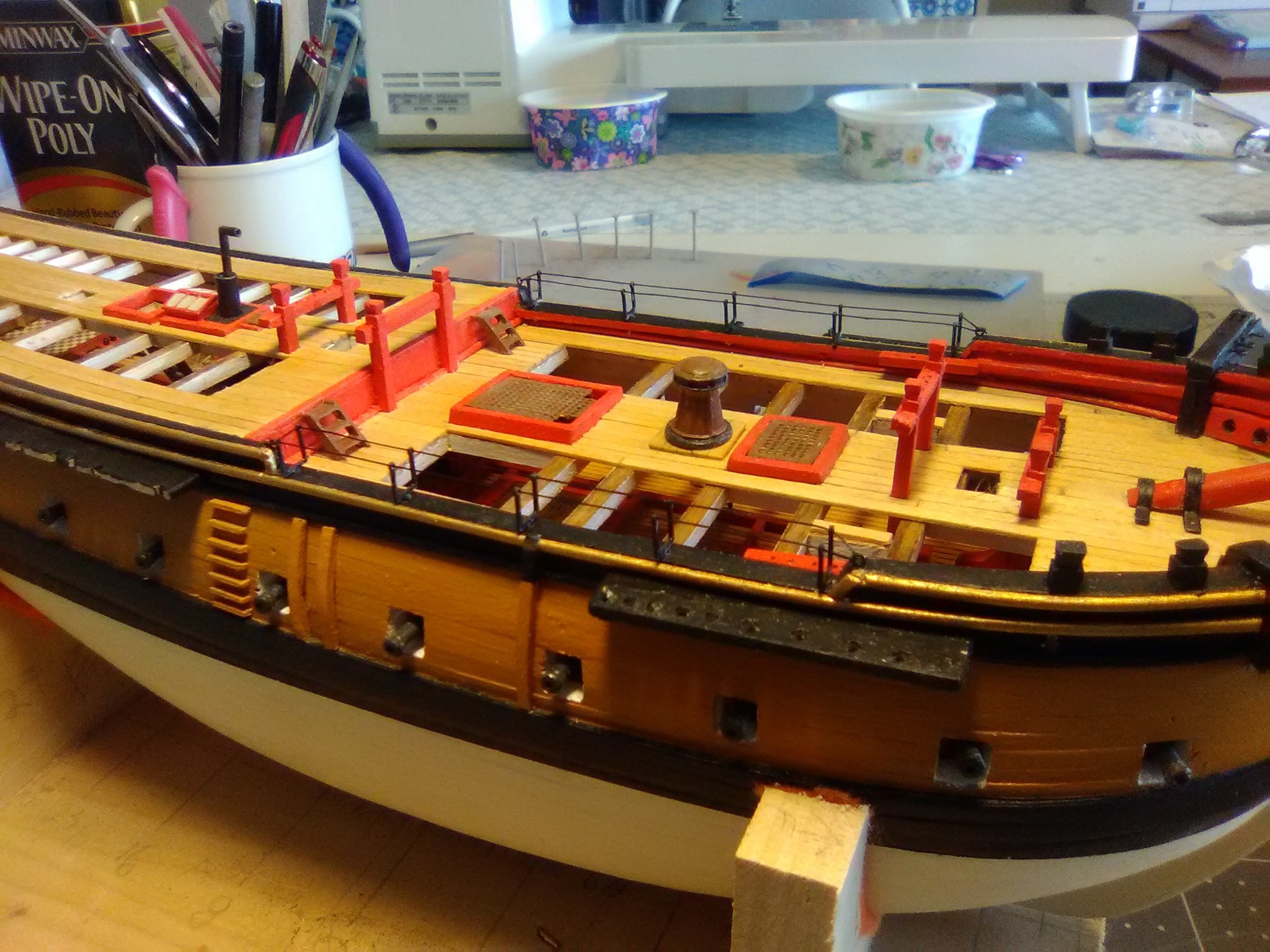
Quarterdeck and Taff rails The rail stanchions were cut using a “Chopper” from Micro-Mark which gave me more consistent lengths than I can get with a hand saw. The directions call for tapering the 3/32” square stock to 1/16” at their upper ends but it does not say whether that is 1/32 off of one side or 1/64 off of opposite sides. Since trying to taper 1/64 is beyond my interest level I took off 1/32 on the inward faces (its too small to notice so that step can be skipped) Then instructions state that open railings like this were a common feature on colonial era ships but since the rails were not strong enough to tie off lines to they had to use pin rails so 6 of those have been added Here’s the railings in place (left long on the aft end to fit in with the taff rail) And here is the final product. Next up will be the stern davits.


- 142 replies
-
- 6
-
-
- alfred
- solid hull
- (and 2 more)
-
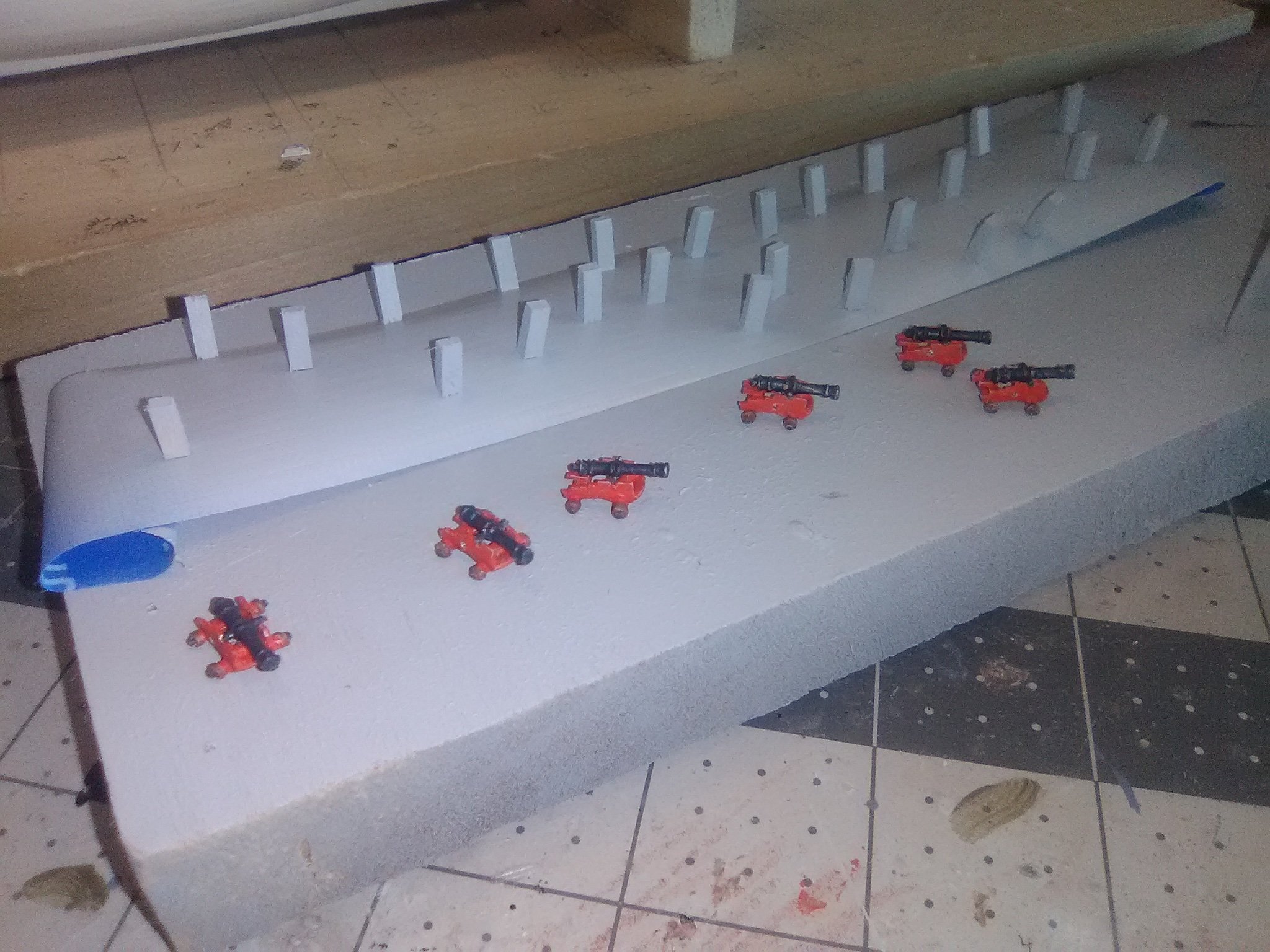
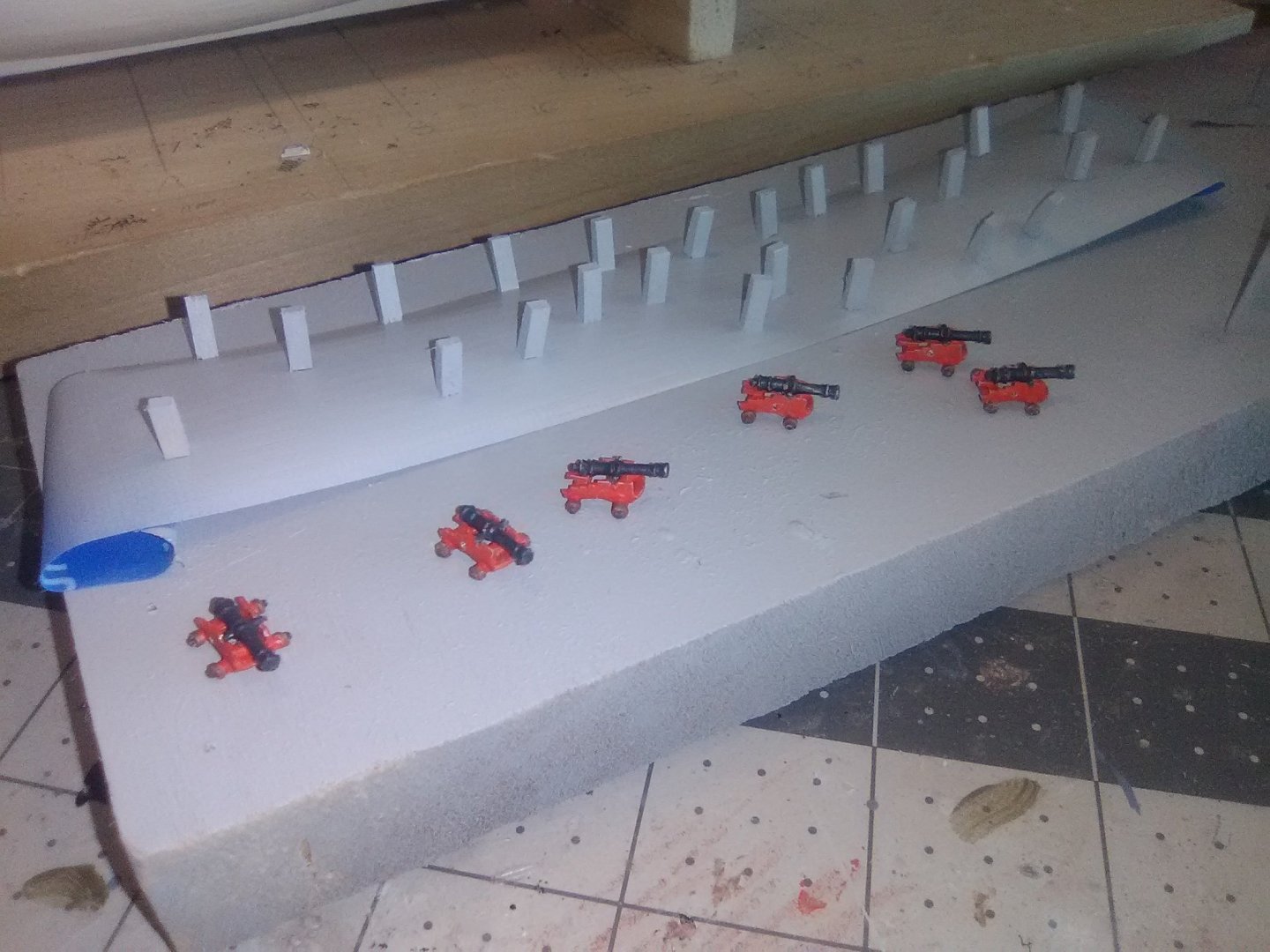
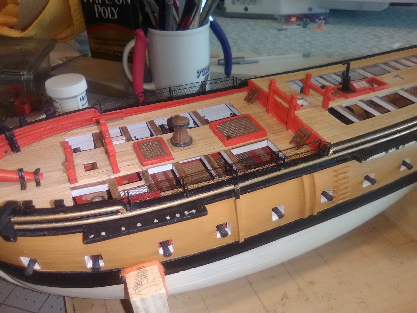
Hammock Netting and the start of the Quarter Deck Railings Modelling time has been a little hard to come by lately so I have not made much progress. The Hammock netting cranes are made up from PE. The instructions call for connecting them with wire but I found that black thread worked better for me. The netting was easy to install as long as a piece of white paper was placed behind it while trimming or it would have been a real strain to figure out what I was doing. The plans call for making 24 stanchions for the quarterdeck railing but the plans only show 22. I made 24 anyway because I’m going to put 1 extra on each side just forward of the taffrail so as to avoid a 9 ft gap without a stanchion. I made up the 4 pounder guns so that I can figure out how high to place the rings on the stanchions for the breeching lines.

- 142 replies
-
- 8
-
-
- alfred
- solid hull
- (and 2 more)
-
Congrats on a wonderful build! It's probably safe to assume that you spent more time building this model than the yacht owners ever spent onboard the real thing.
-
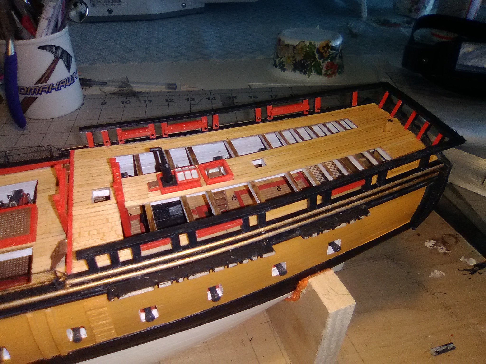
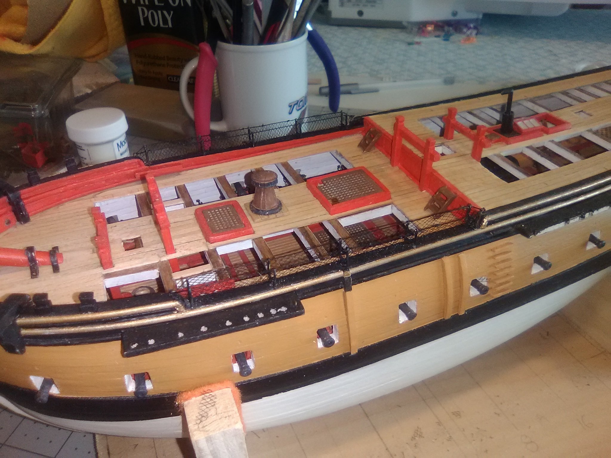
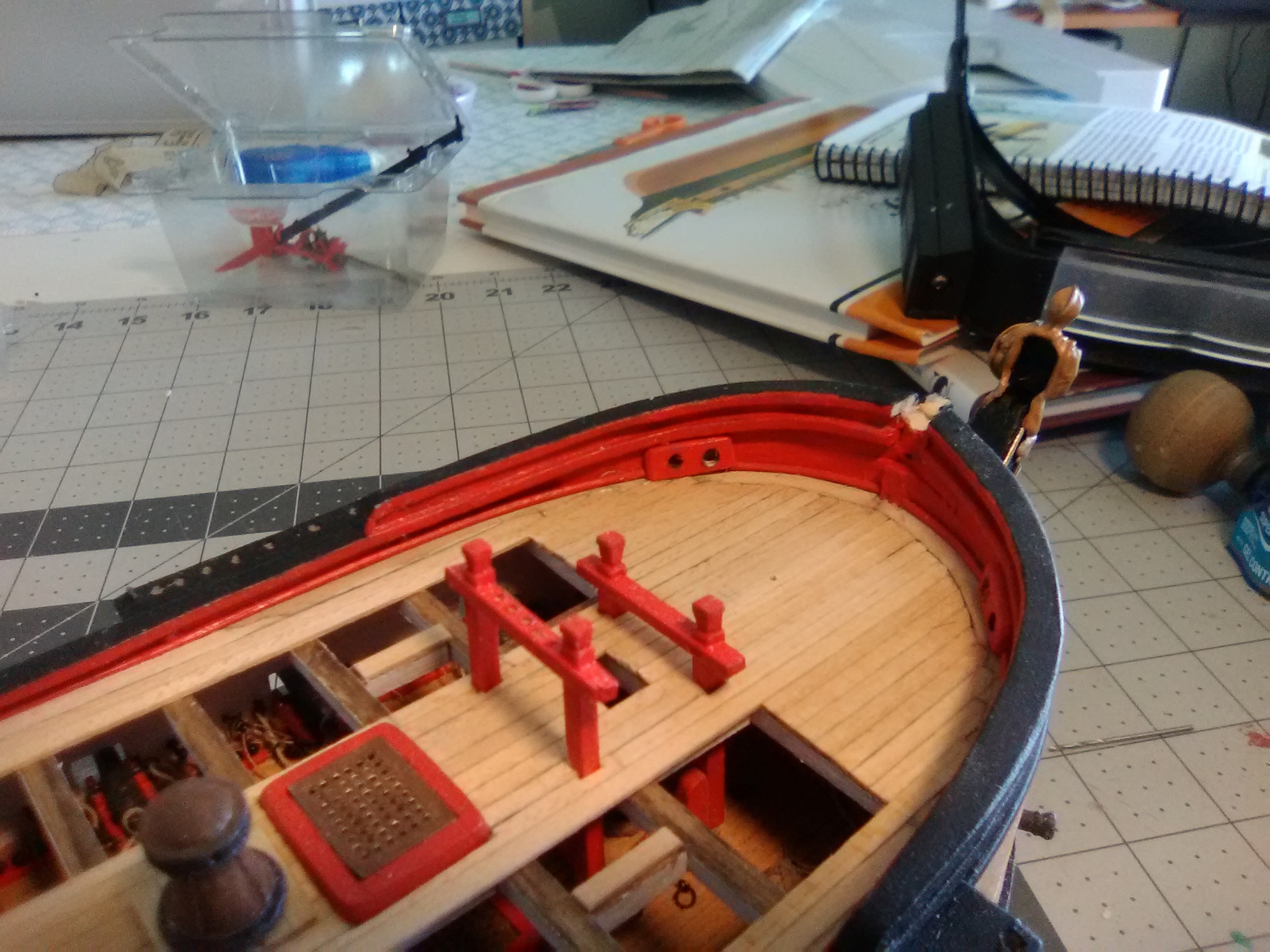
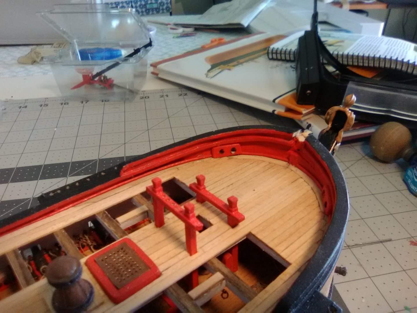
Knightheads and Timberheads I’ve made very little progress lately because of outside distractions. The next step in the build is to fabricate and install the main deck pinrails, knight heads and timber heads. They were easy to shape out of the supplied strip wood. Instead of using the plans for their placement I used the belaying diagram in the instruction book which gave a better view of their spacing: Next up will be the hammock cranes along the lower part of the bulwarks

- 142 replies
-
- 5
-
-
- alfred
- solid hull
- (and 2 more)
-
Tom, This is a really interesting kit and your quality of work is excellent! I was interested to see that the kit provides detailed deck framing. Have you considered leaving off the main deck planking on one side (the side away from the viewers would be best) from the centerline to the waterway so all that detail (and some of the berth deck details) could be visible? Keep up the good work - I'm looking forward to the rest of this build.
- 163 replies
-
- 1
-
-
- Model Shipways
- Constitution
- (and 2 more)
-
Looking really good!
-
Re-Do on the gilt trim Although I did not mention it in my last post the photos show the gilt trim along the main and fancy rails. The instructions suggested using a paint pen, which I have never used before but I gave it a shot and to my aging eyes I thought it looked pretty darn good … until I saw the photos “blown up” here on the site, which makes my photos more “close-up” than they appear on my computer. Boy, it looked bad!! In retrospect it probably would have worked fine if I had made sure the surfaces were smooth and the edges sharp rather than rounded. Some tape probably would have helped too but at that point I probably would have just used regular paint. So anyway, all that was sanded off and replaced with 1/16” half round strip from BlueJacket (their catalog lists it under “moulding strips”) that were primed and painted off the model. If I had to do it again I probably would have used the “double-bead” strips for the fancy rails for a little contrast. This is a big improvement over my first attempt. Next up will be the knight heads and timber heads around the foc’sle.


- 142 replies
-
- 7
-
-
- alfred
- solid hull
- (and 2 more)
-
Very clever work on the volutes!
-
Finishing up the Head Rails As I mentioned in an earlier post, britannia metal does not stand up to multiple bendings so I used a piece of wire to get the shape of the upper rails set: I then transferred that shape to the britannia, attached the channel plastic to its outside face and put them in position. The support timbers that run vertically between the rails were easy to make out of britannia strip. The final details were the netting and the 4 “seats of ease”:


- 142 replies
-
- 5
-
-
- alfred
- solid hull
- (and 2 more)
-
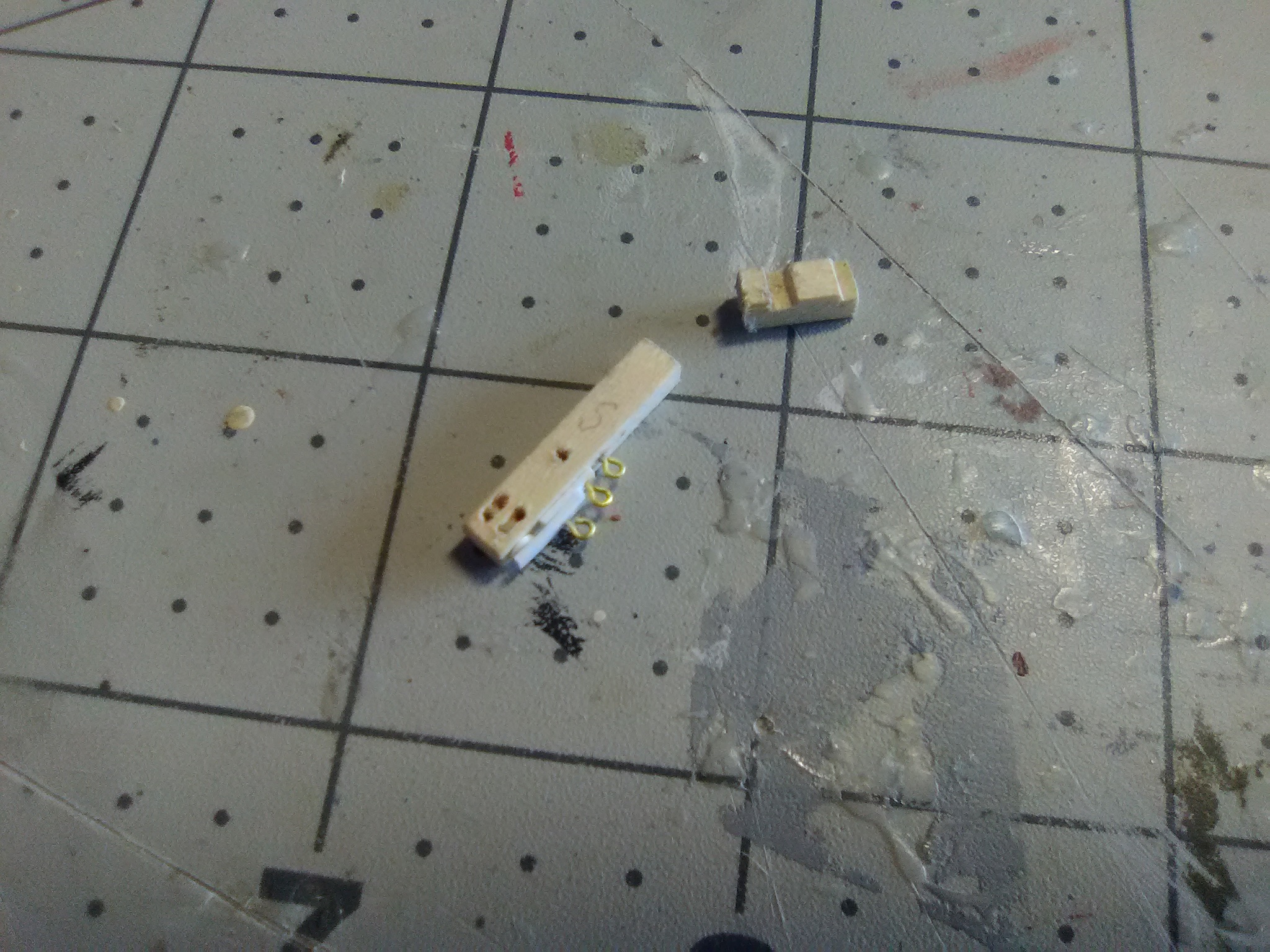
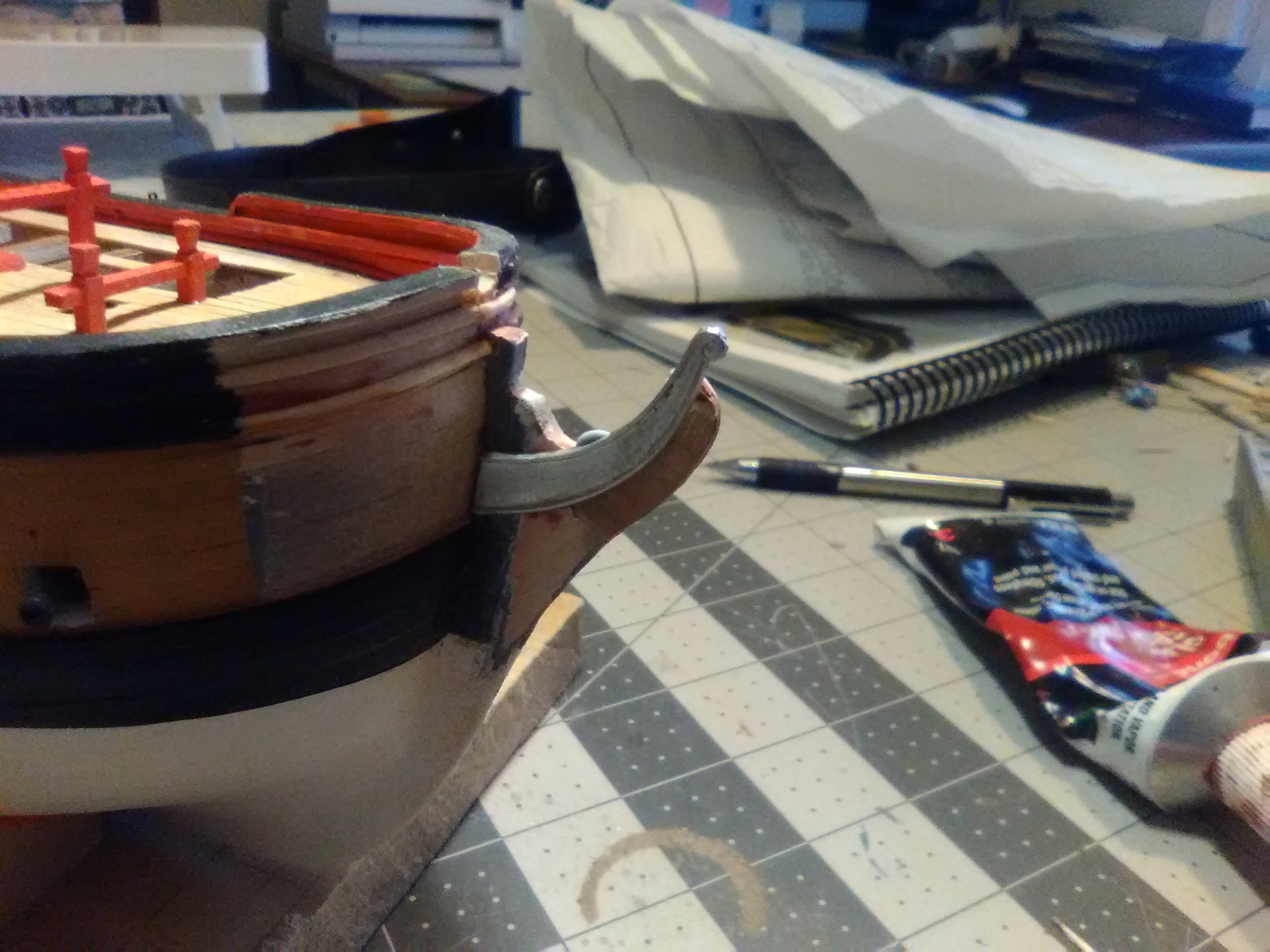
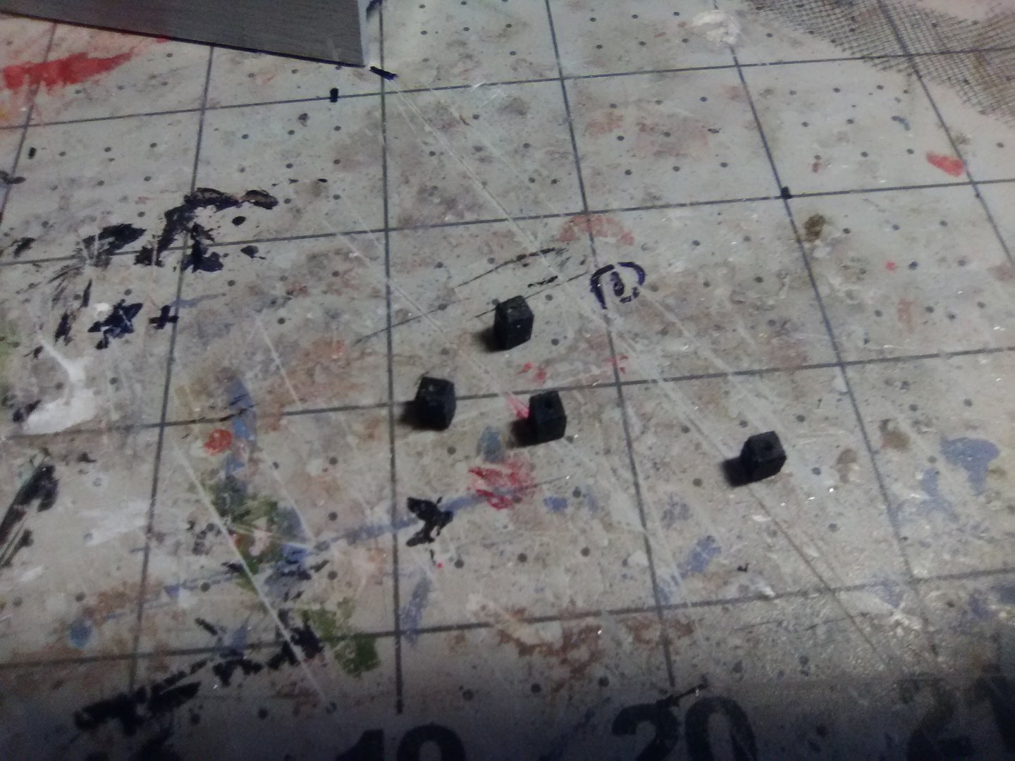
Catheads The catheads were fabricated out of 1/8” square stock. The inner piece had to be notched to fit over the main rail and the waterway. The top piece has fake sheaves (2 pairs of holes, each pair linked with a “trench” connecting them). Plastic strip was used to make up the exterior sheave that will be used for the cathead stopper cable: The knees under the catheads were made from 1/8” sheet. A piece of card stock was used as a template: With these done I can resume work on the headrails.


- 142 replies
-
- 3
-
-
- alfred
- solid hull
- (and 2 more)
-
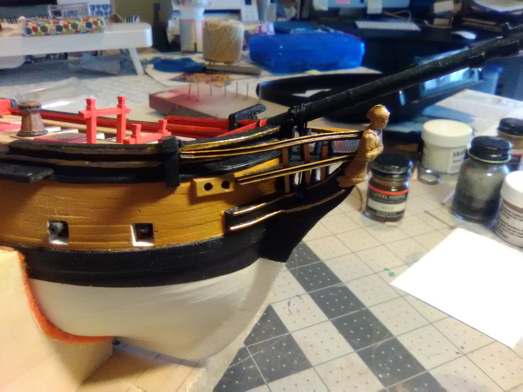
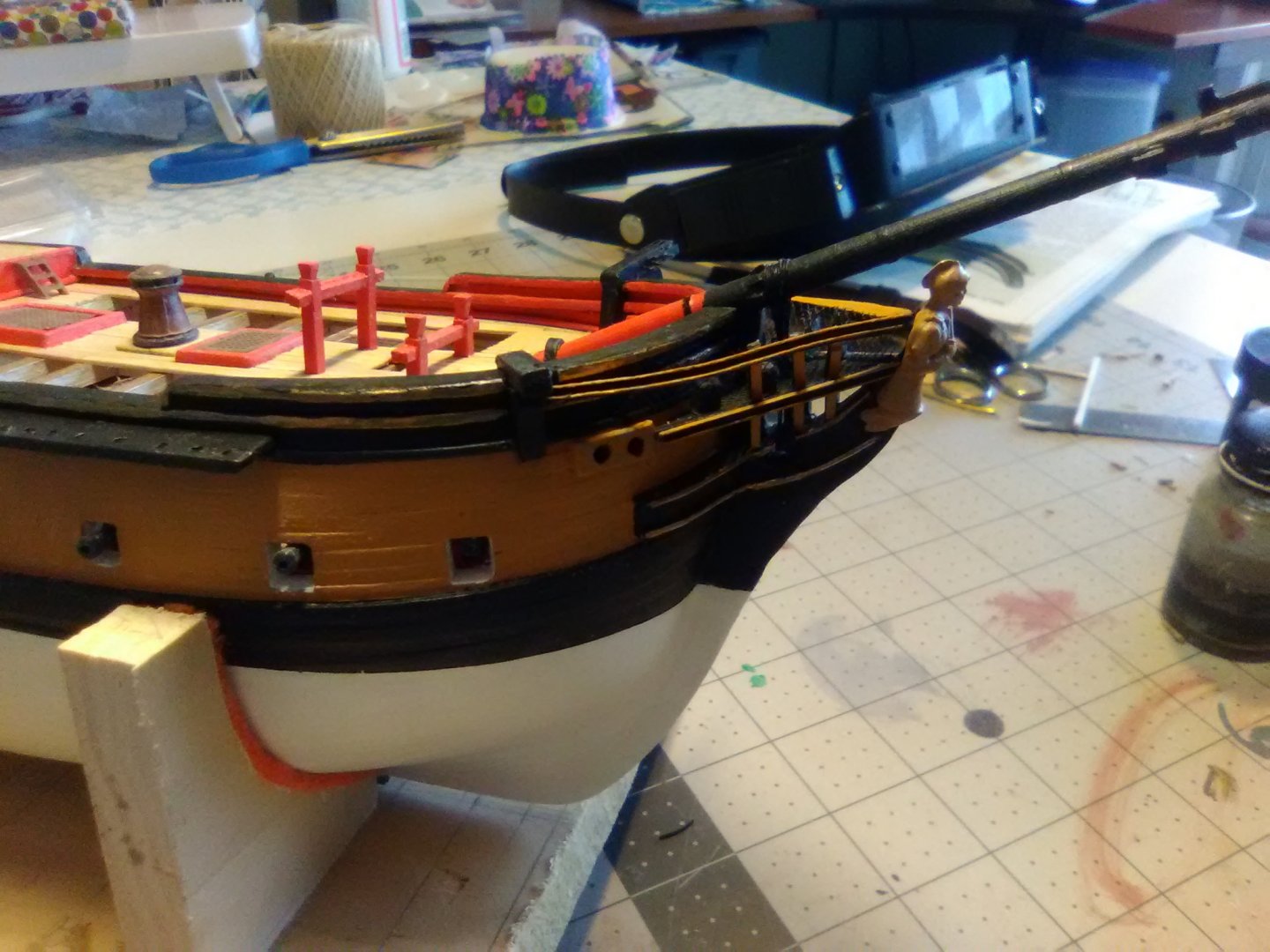
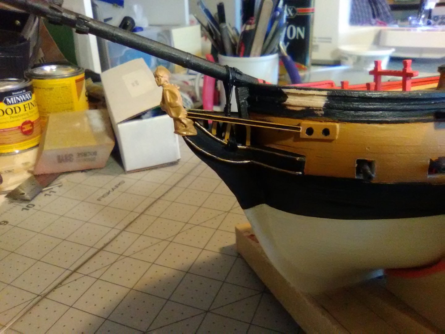
Bow Rails half done The kit provides some 1/16” x 1/16” britannia strip metal for the bow rails. It is nice stuff to work with in this type of application. It cuts and sands easily and you can easily bend it into almost any shape with no spring back. The only thing you have to watch out for is that it will not stand up to multiple bendings - if I know it will take me several tries to get the right shape I use a piece of brass rod or wire as a template and then bend the britannia to match it. I was playing around with the britannia when it occurred to me that it would work well to make the small timbers that run from the stem to the underside of the bow grating. The timbers are supposed to be concave and making them from wood involves a lot of trial and error but the britannia is exactly the width call for in the plans and it was an easy job to fit all 6: The next step was to place the lower rails along the outboard sides of the grating, pretty simple since there are no bends. The only problem is on all the period models I’ve seen they usually have some sort of decorative moulding on their outboard face which would be pretty hard to do with only 1/16” to work with. I was going to try it with some thin plastic rod like I used on the cheeks but I found some thin u-shaped channel material (Evergreen Scale Model .060" channel, item # 261) in my plastic stash that fits the outboard edge perfectly. After trying several color combinations of buff, black and gold I settled on buff and black: I can’t do the upper timbers and rails yet because the upper rail fits against the cathead knee so I will have to put the catheads in first. I also needed to order more britannia strip from BlueJacket since using them on the timbers did not leave enough for the second half.

- 142 replies
-
- 5
-
-
- alfred
- solid hull
- (and 2 more)
-
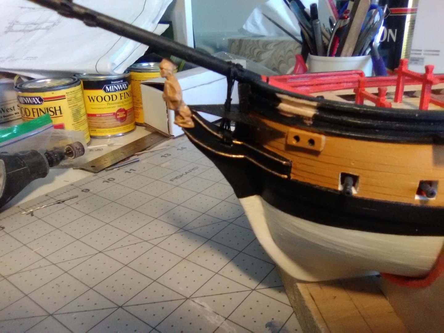
Hi Thunder, thanks for the kind words. I had the same thoughts about the hawse locations, like you I'm used to seeing them closer to the stem and maybe on the deck below. My guess as to why this is setup this way was that ALFRED was built as a merchant ship and converted to a light frigate in a relatively short time. One of the big differences between her and purpose-built warships was that, although the ALFRED had a capstan, it did not go down to the gun deck and was apparently used just to haul the anchor hawser up from the cable tier. To actually raise the anchor a windlass was used (it will be fitted after the mast rigging is done) probably because merchant ships did not have the manpower to operate multi-deck capstans and it must have been a very slooooow way to raise the anchor. When the windlass is fitted it's heads are directly in line aft of the hawse holes, well out board of the the bits so I'm guessing they must have used some type of line stoppers to take the strain while the ship was at anchor. Definitely not the effecient set up on the ships you have modeled.
- 142 replies
-
- 1
-
-
- alfred
- solid hull
- (and 2 more)
-
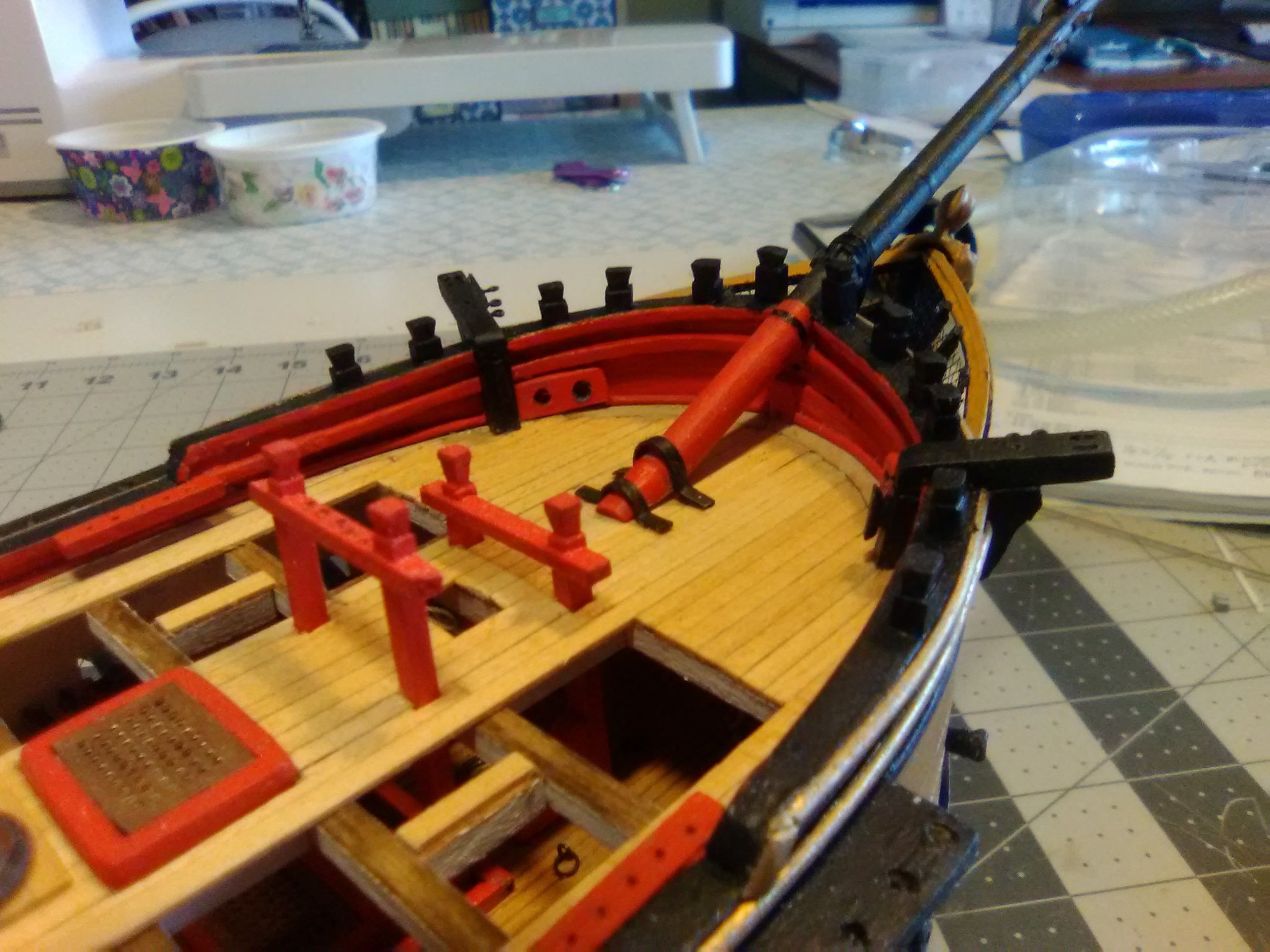
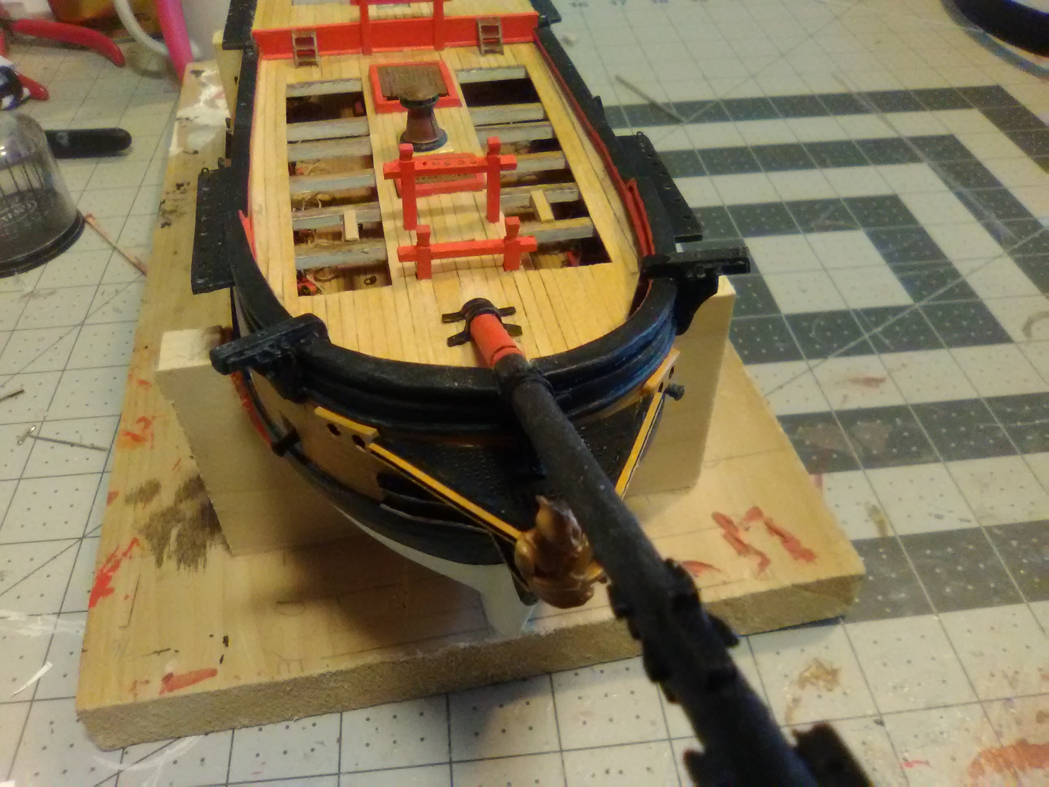
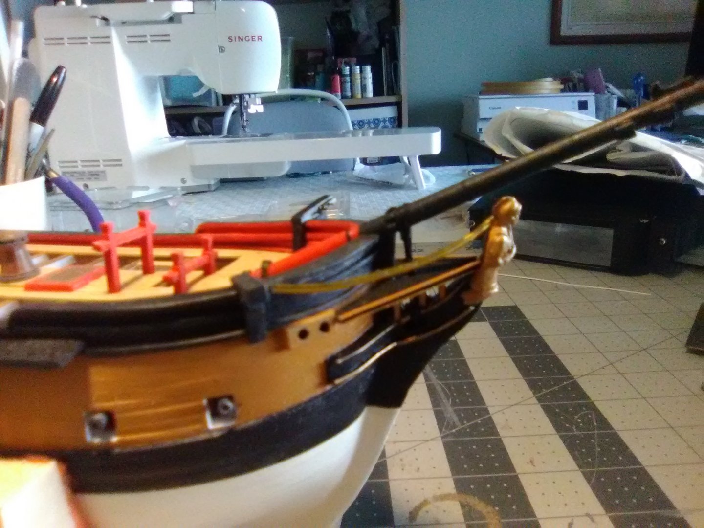
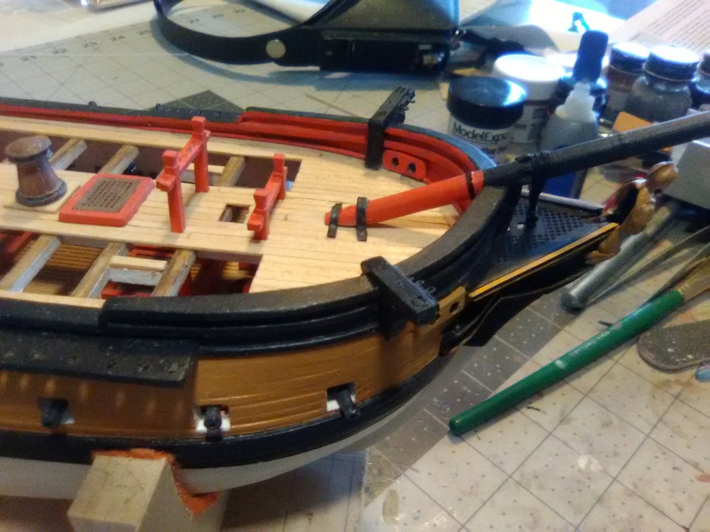
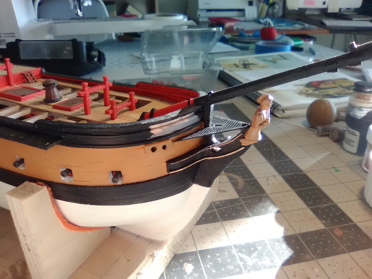
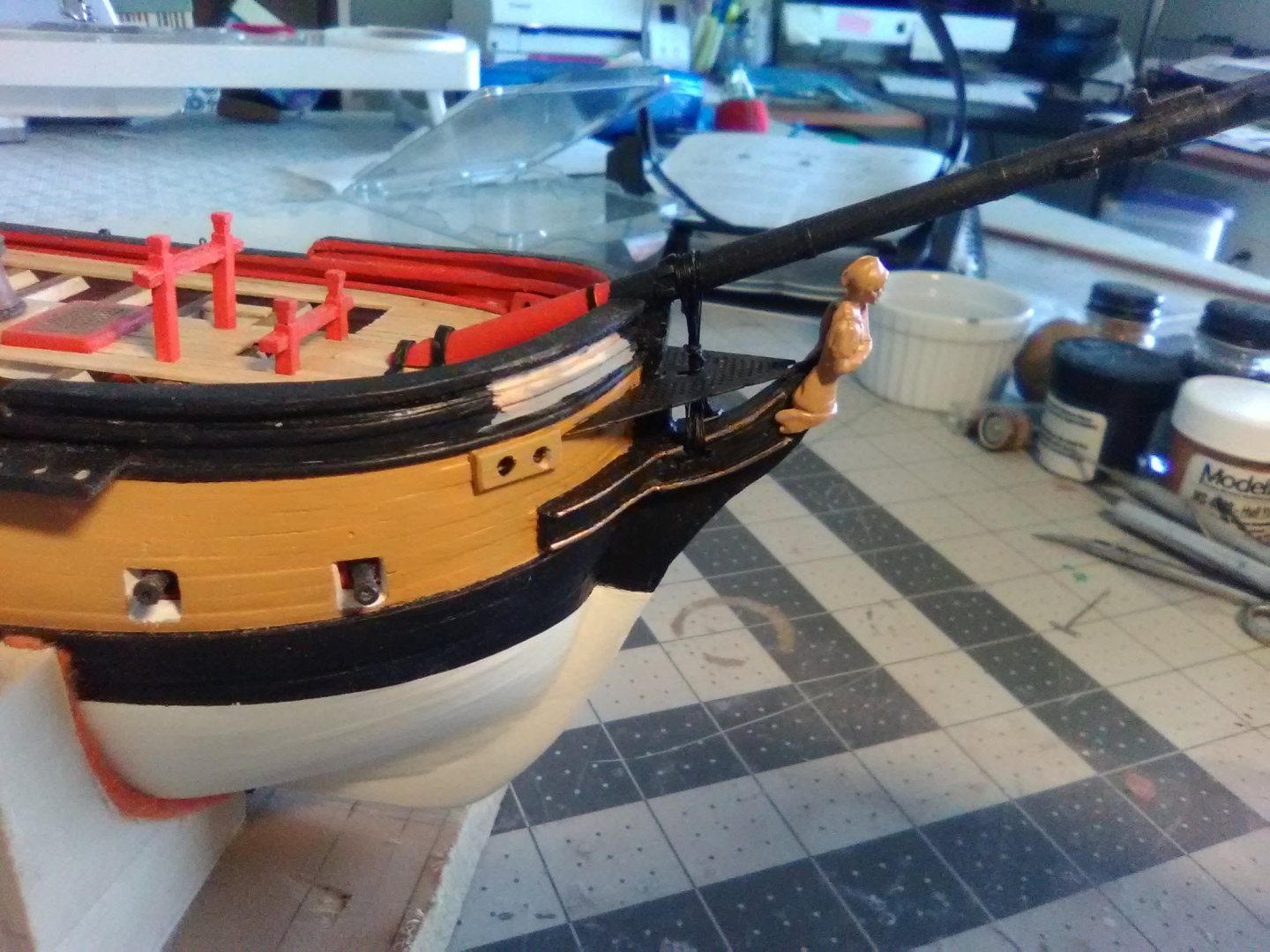
Head Grating, Bowsprit and Gammoning I was going to try to fit all the timbers that support the grating befor installing it but it quickly became obvious that the easiest way for me to do it was to put the grating permanently in position and then fit the timbers individually. Here is the grating in place - the aft edge is even with the main deck and it has an “upslope” as it goes to join the stem. The bowsprit has also been pinned and glued in place so that I can rig the gammoning before the rails and timbers make it harder than it has to be: The gammoning went on easily although it took me a while to understand what the directions meant by each figure 8 “crossing over” the previous one. When you rig it if you make sure that each loop over the bowsprit is forward of the previous one and that each loop thru the gammoning slot on the stem is aft of the previous one then you will be all set.
- 142 replies
-
- 7
-
-
- alfred
- solid hull
- (and 2 more)
-
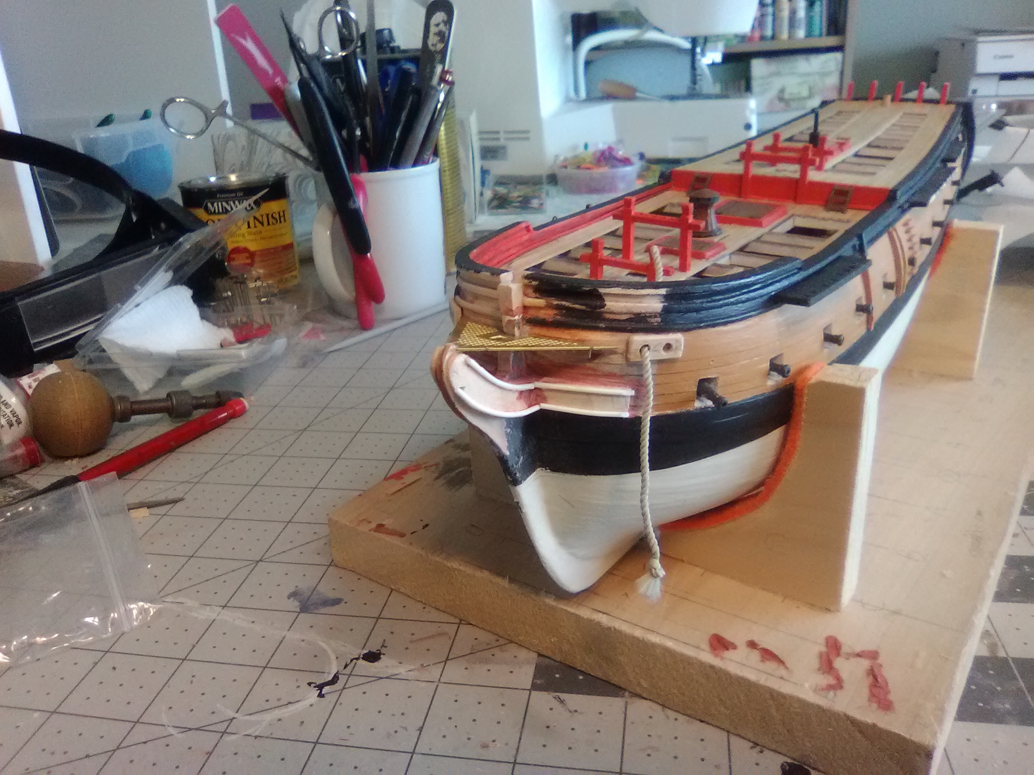
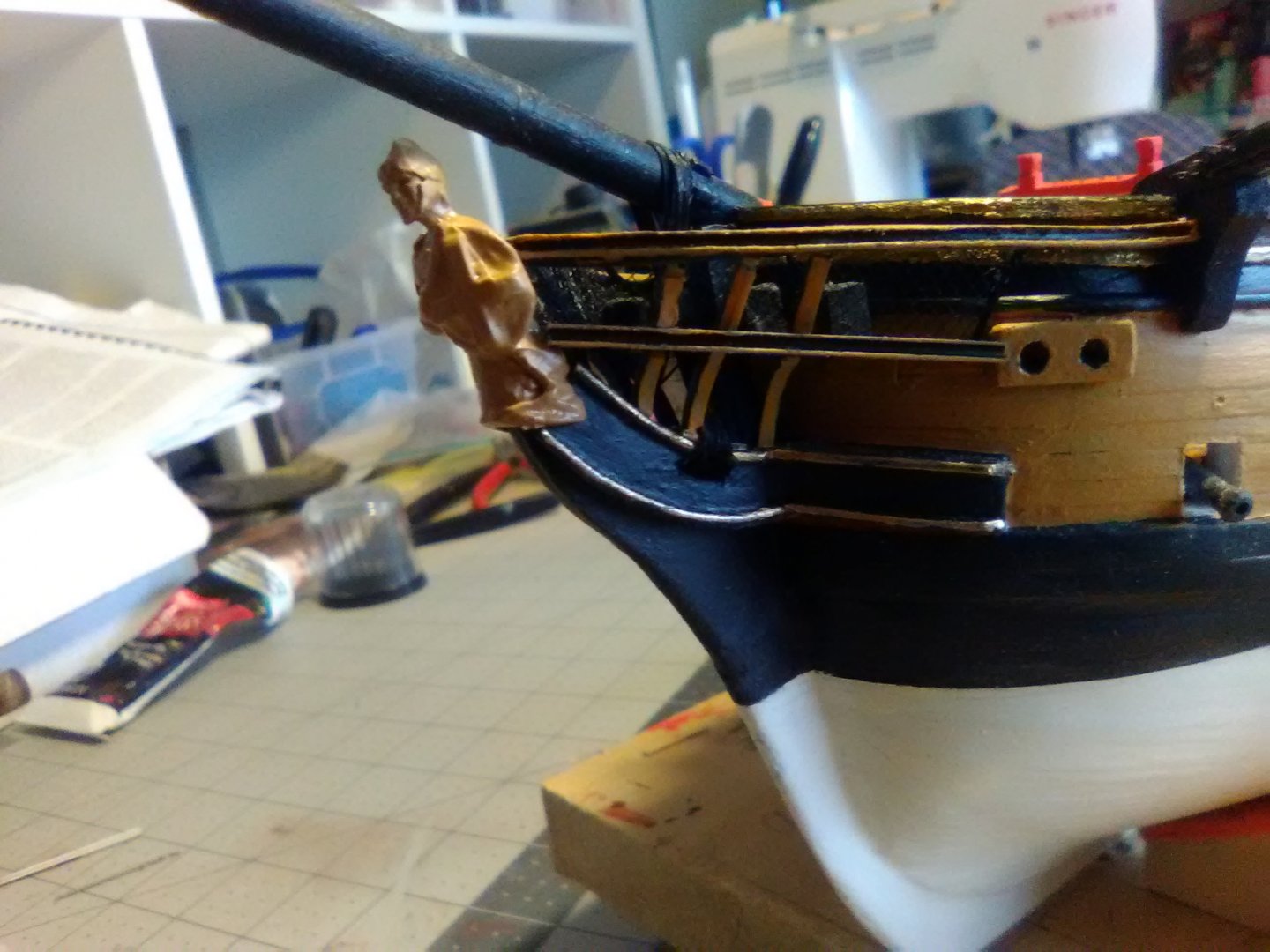
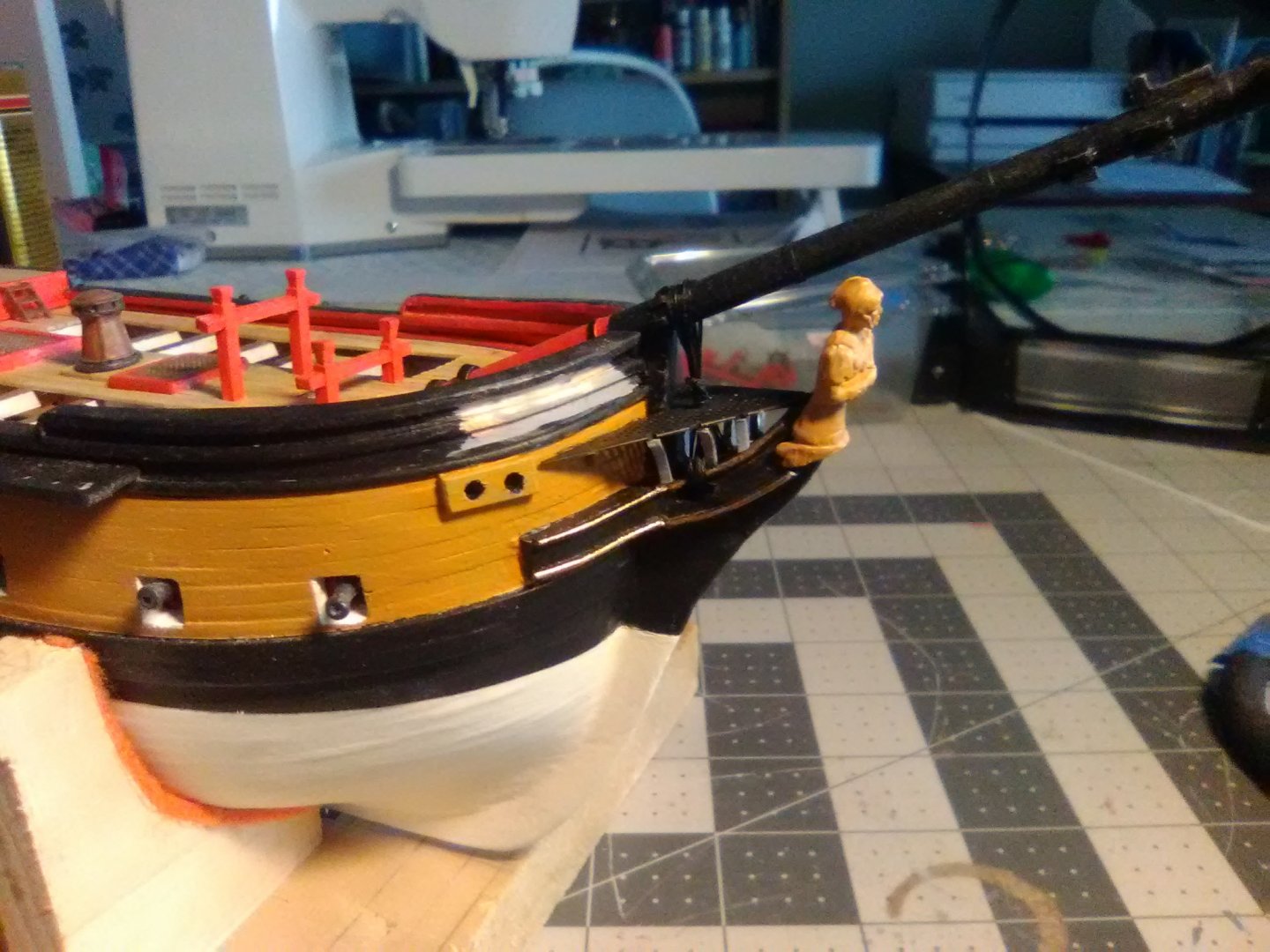
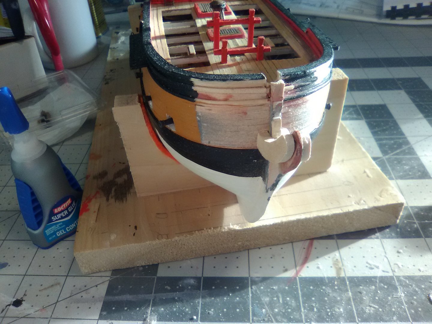
Finishing the Cheeks and Hawse Bolsters The half of the cheeks that rest on the hull were made of 1/8” thick strip wood the same width as the stem cheeks and the moulding was made from plastic rod. The hawse bolsters were placed at the outboard corners of the head grating: After painting and the addition of the figurehead the stem is pretty well set with the exception of the slot for the gammoning, which as can be seen, I’m still in the process of drilling and filing out: The instructions call for drilling out the hawse holes as one of the last steps in the build which did not make a lot of sense to me since it would have been really hard to clean up all the tear-outs on the inside of the bulwarks with all the rigging in place so I did it now. To help cover up the tear-outs I added interior bolsters which I have seen on other builds from this era.

- 142 replies
-
- 8
-
-
- alfred
- solid hull
- (and 2 more)
-
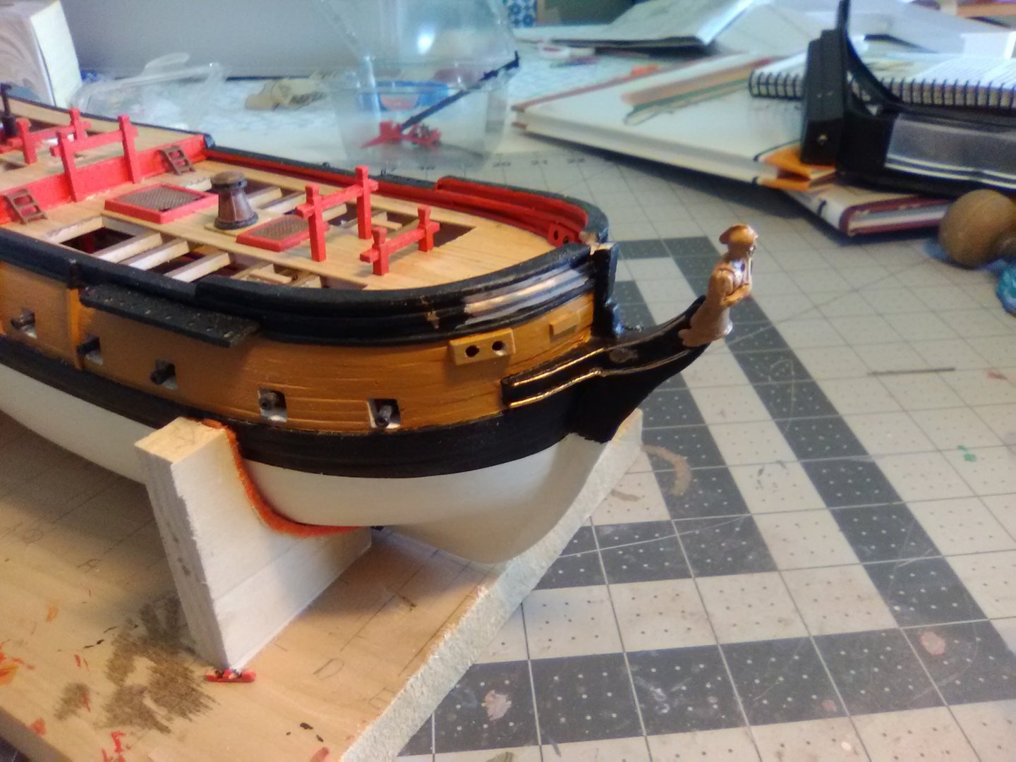
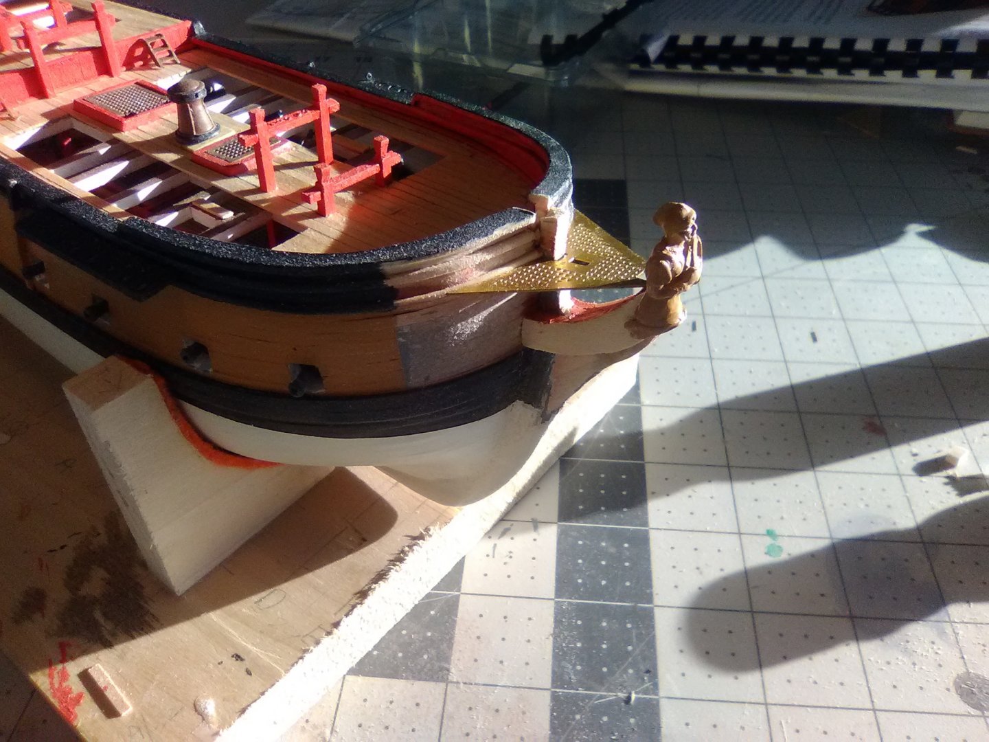
Starting the Cheeks and Trail Boards The cheeks are large structural assemblies that help strengthen the stem. There are usually 2 parts; one on the stem and one that continues along the bow, on or above the wales. The cheeks on the stem have another layer called the trail boards which usually have some decoration, or at least some moulding. The kit provides a brittania metal piece for the trail boards. It is different than the shape of the tailboards on the plans and from the general shape of my stem area: I traced the trail board from the plans, at least as much of it as was shown, the outermost part literally disappears up the figurehead's backside but the general shape can be assumed. I like this shape better so I will go with it: Since the cheek under the trail board was supposed to be trimmed to match the shape of the trail board I will effectively be combining them into one piece. I shaped it out of 1/8” stock and glued them on each side of the stem: Once in place the stem cheeks should be tapered to that their outboard ends will fit inside the opening on the back of the figurehead. The kit-supplied brittania figurehead was a pleasant surprise. It needed no cleanup at all and the detail is amazing: The rear opening of the figurehead is well done, the lower half is slightly wider to accommodate the combined widths of the stem and both cheeks and the upper half is slightly narrower where all the rails will fit into (hopefully): After tapering the figurehead sits snuggly on the end of the stem, and although I don’t show it here, its’ top is right about 1/8” below the bowsprit, as called for in the plans.


- 142 replies
-
- 5
-
-
- alfred
- solid hull
- (and 2 more)
-
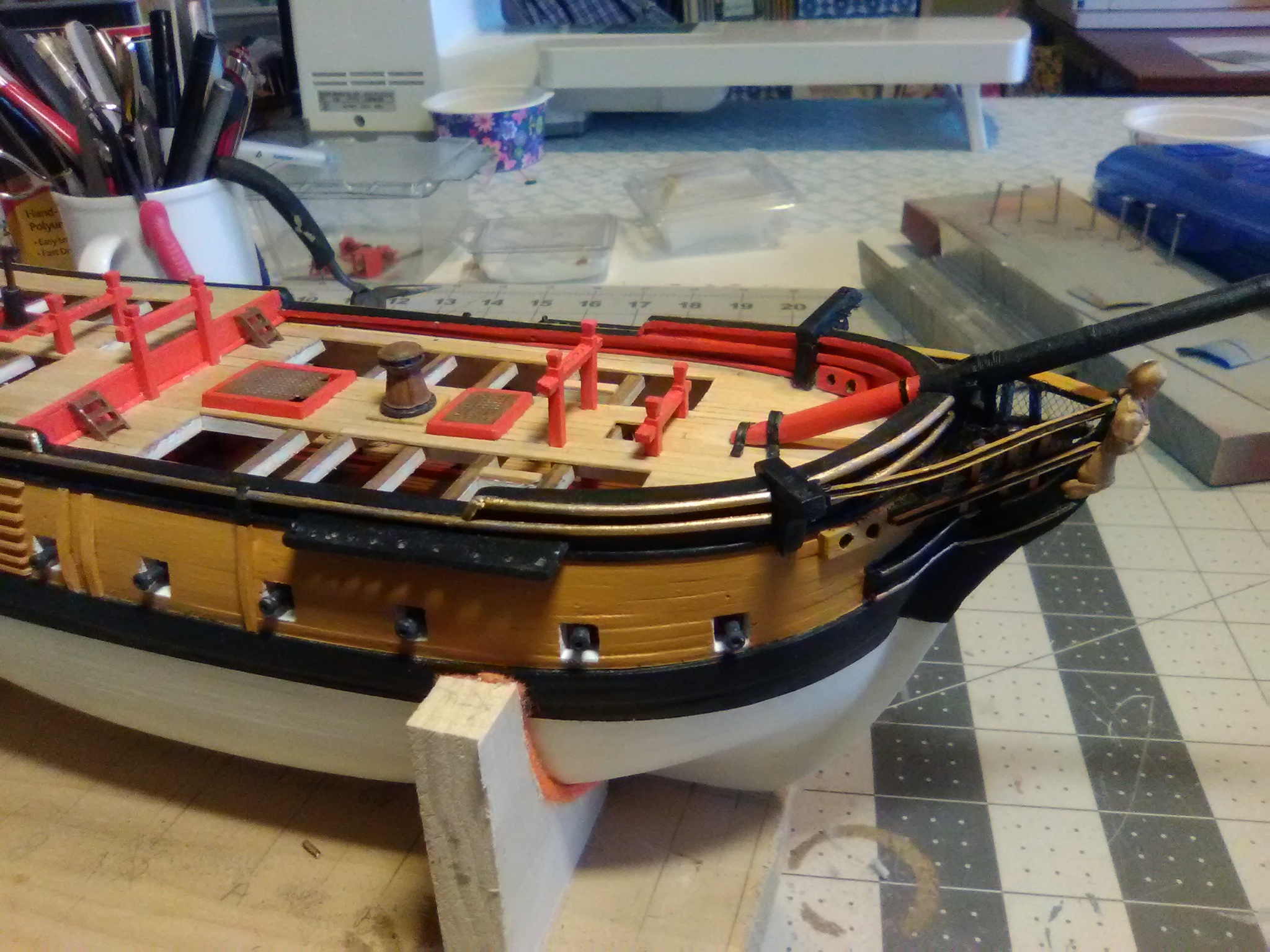
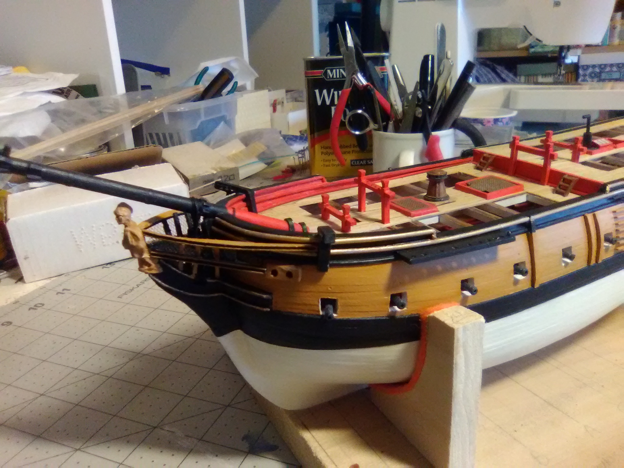
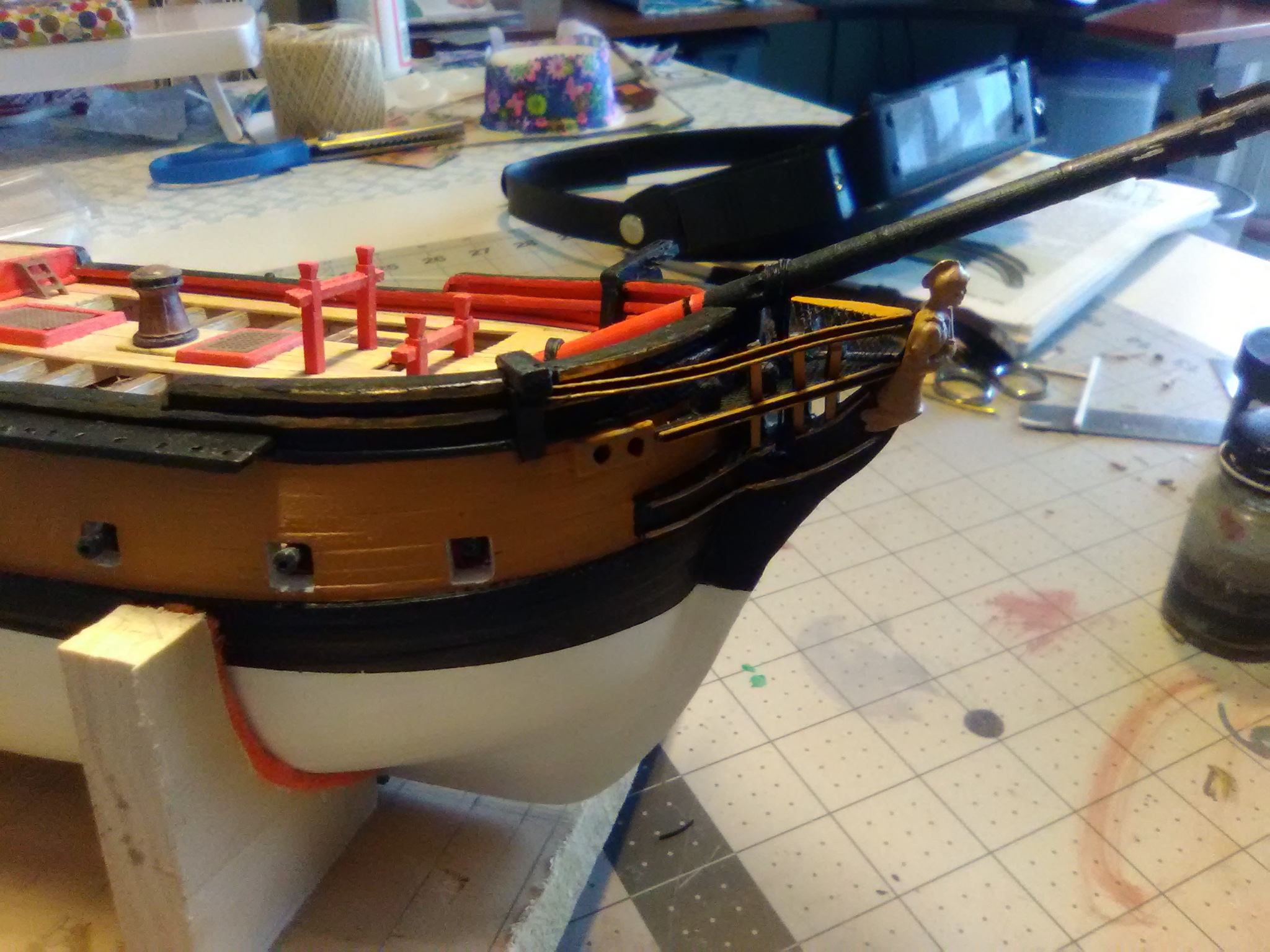
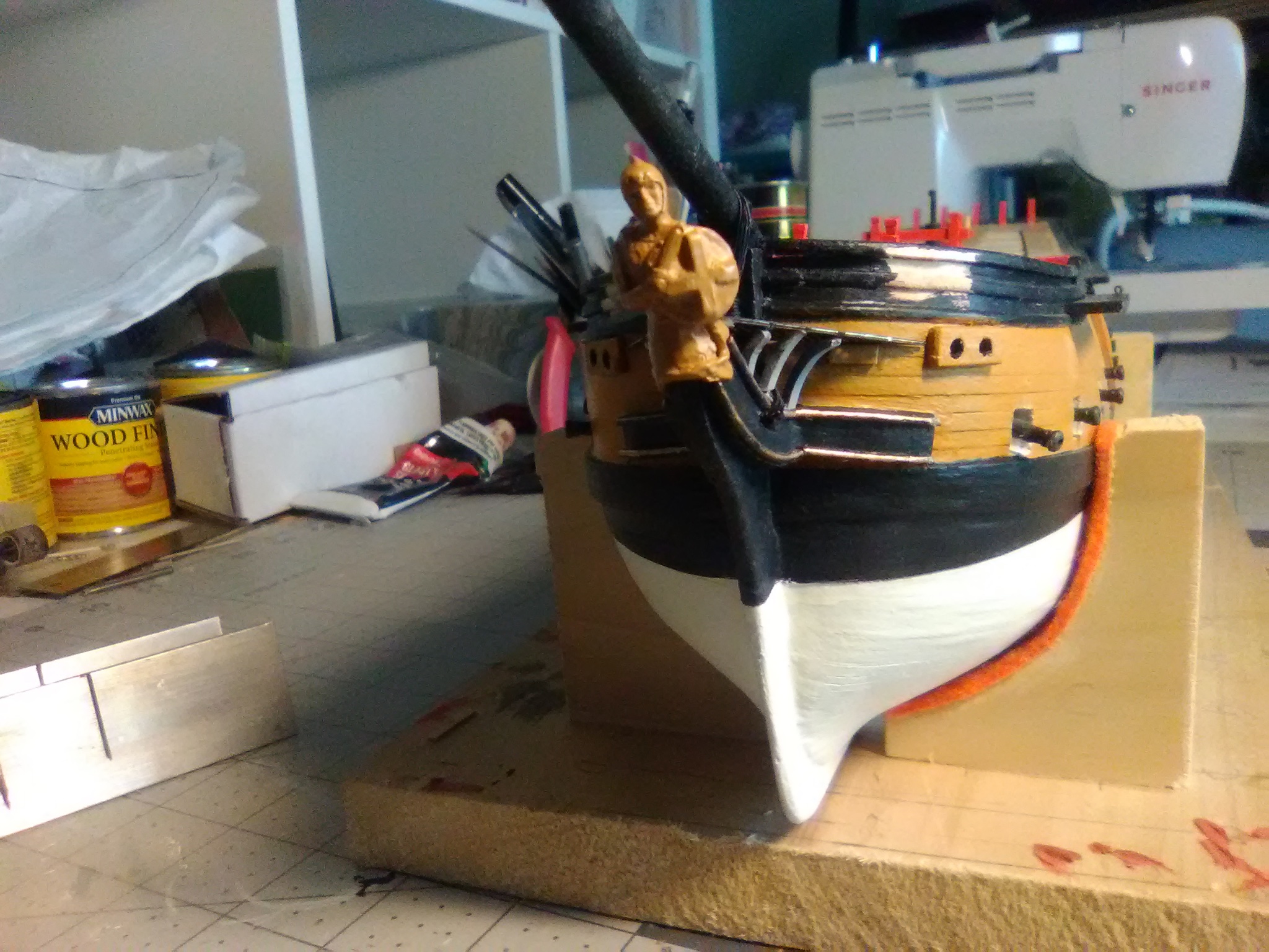
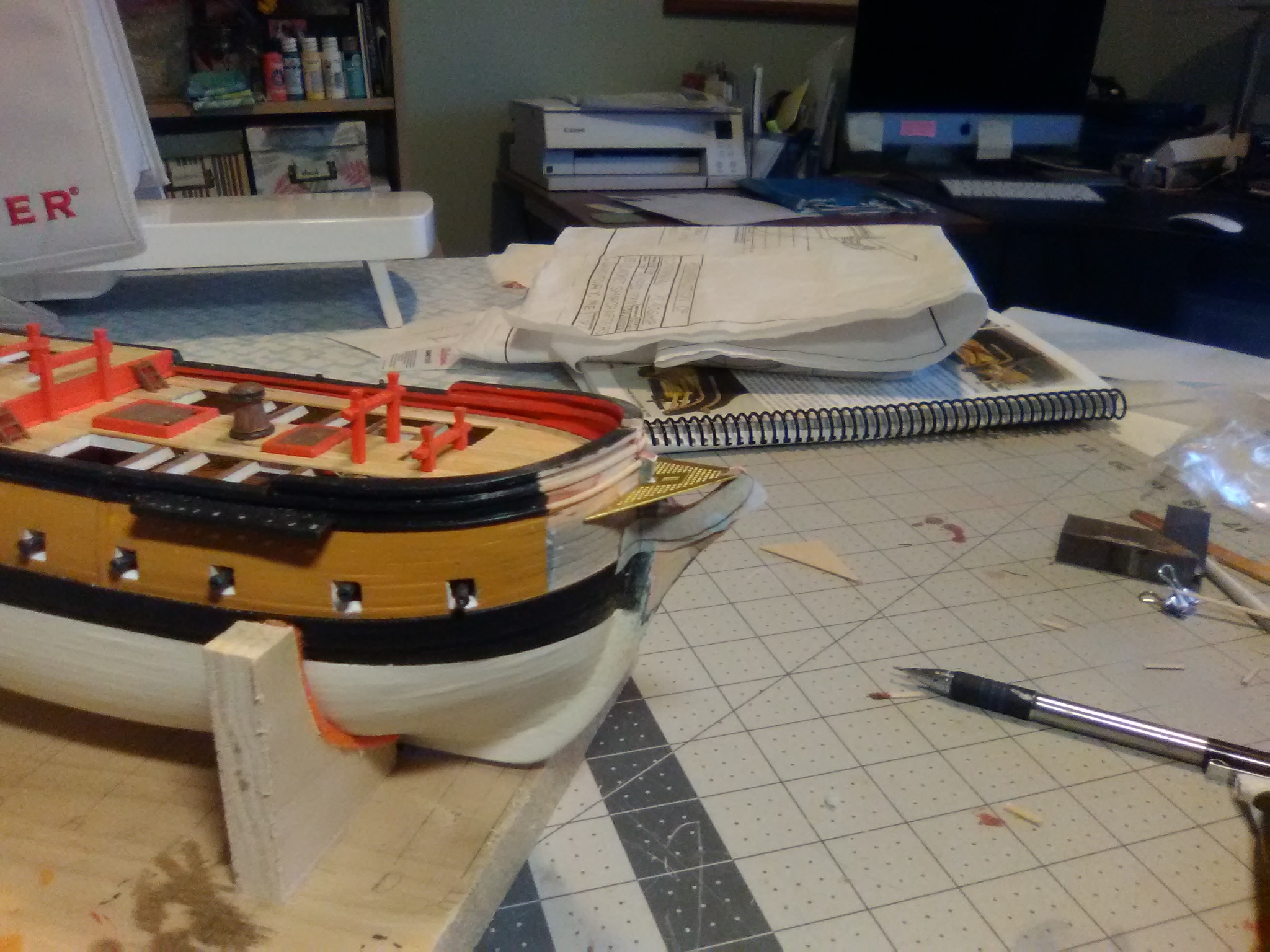
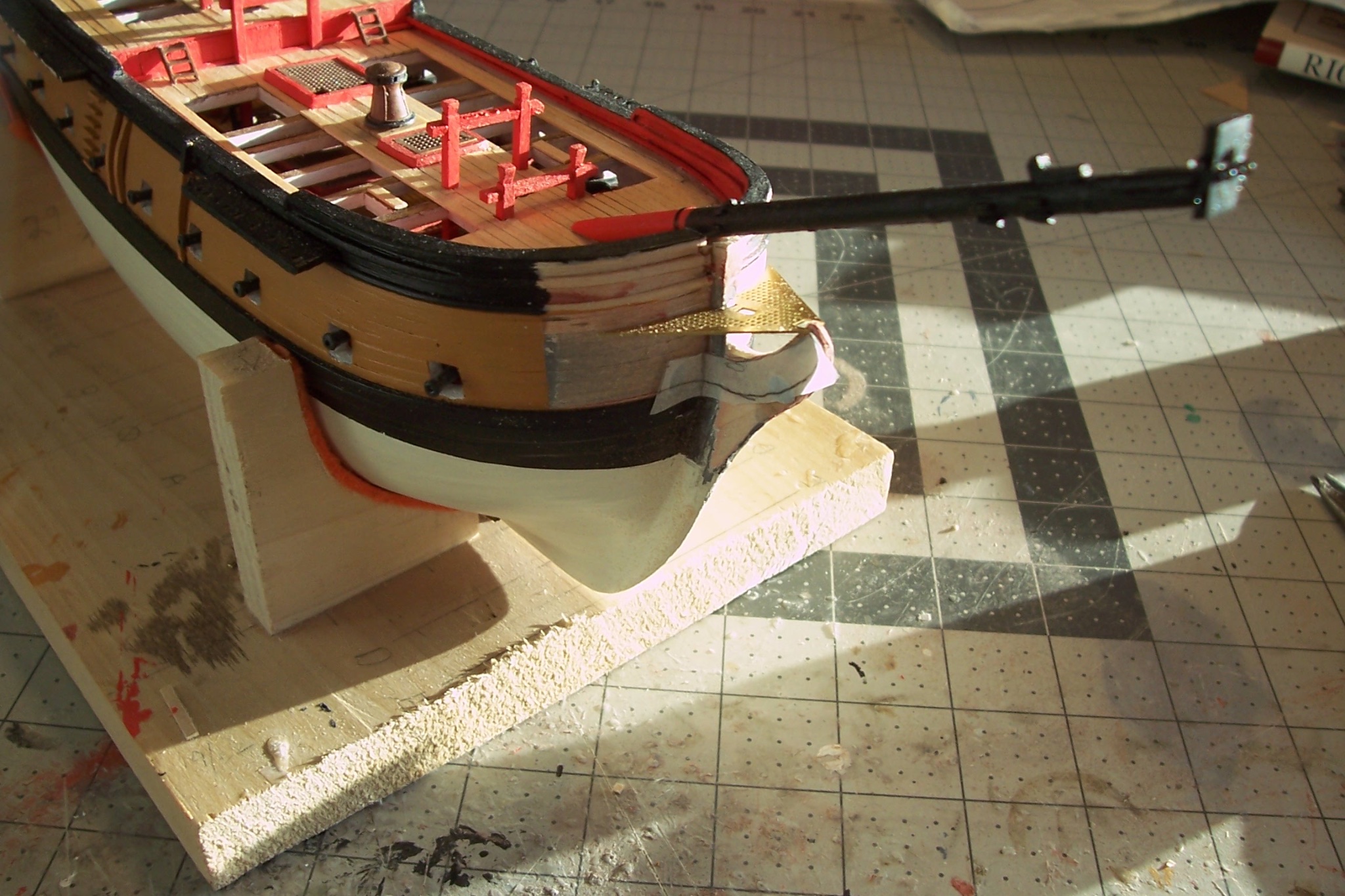
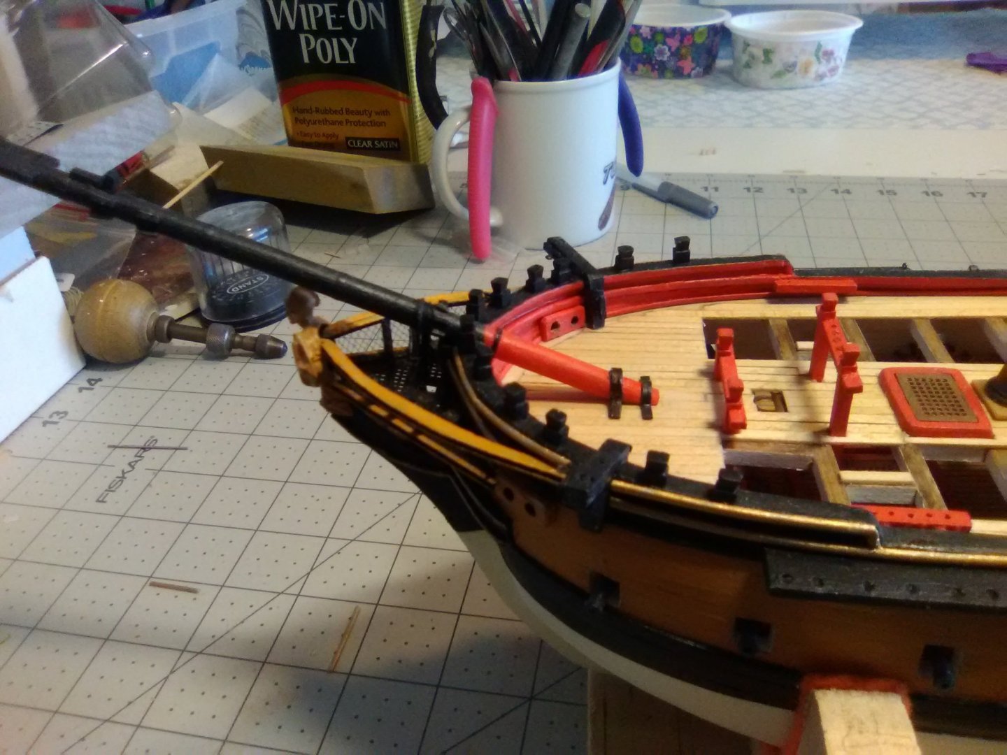
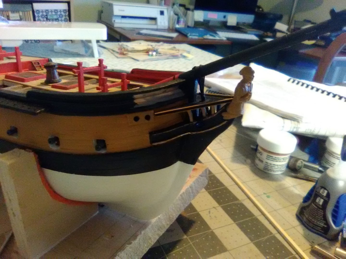
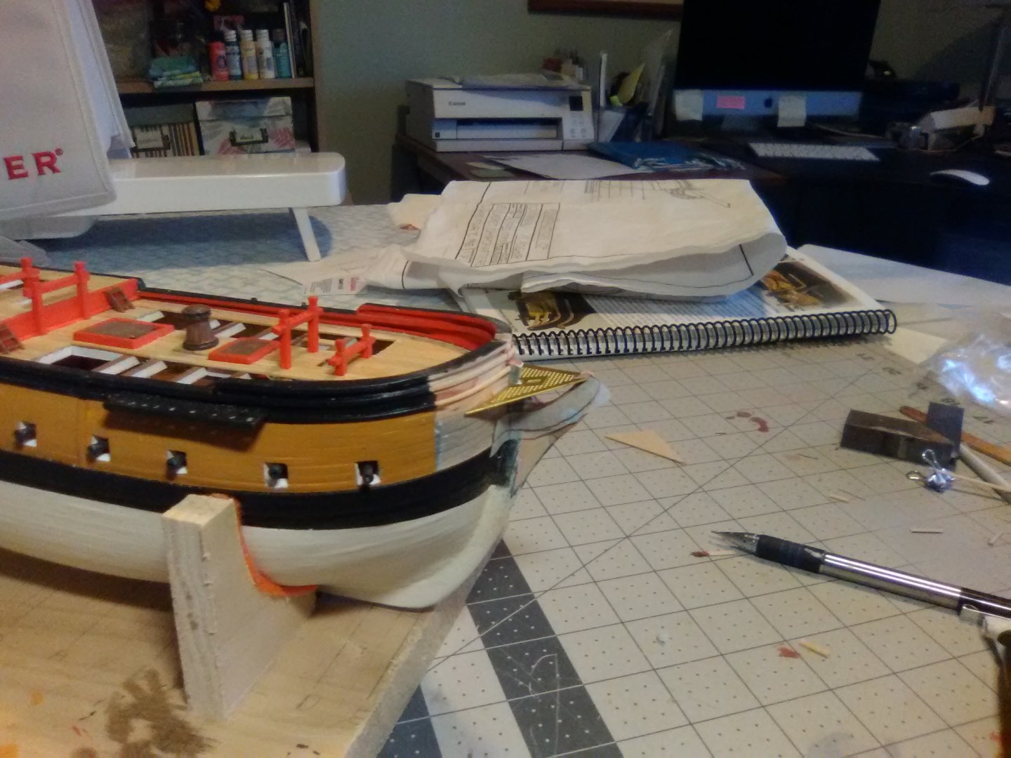
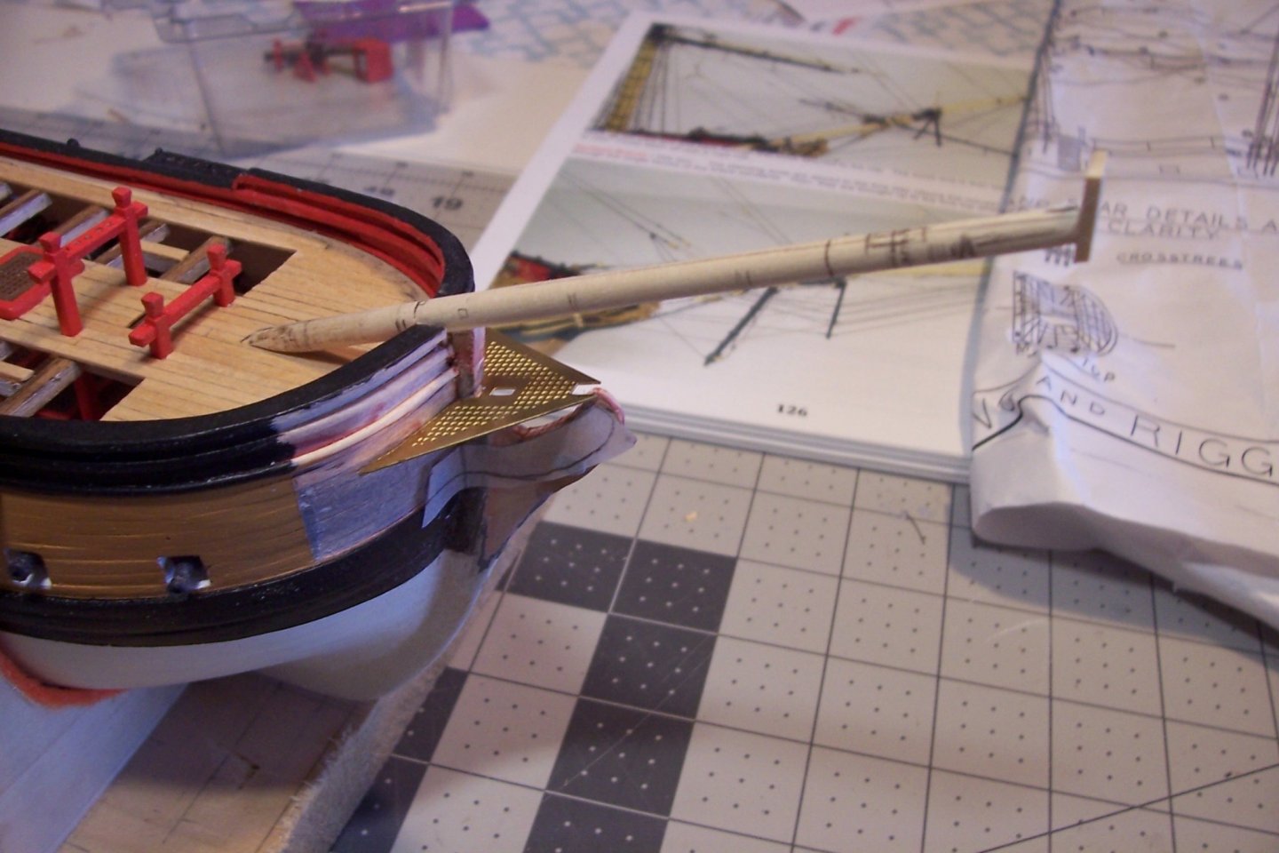
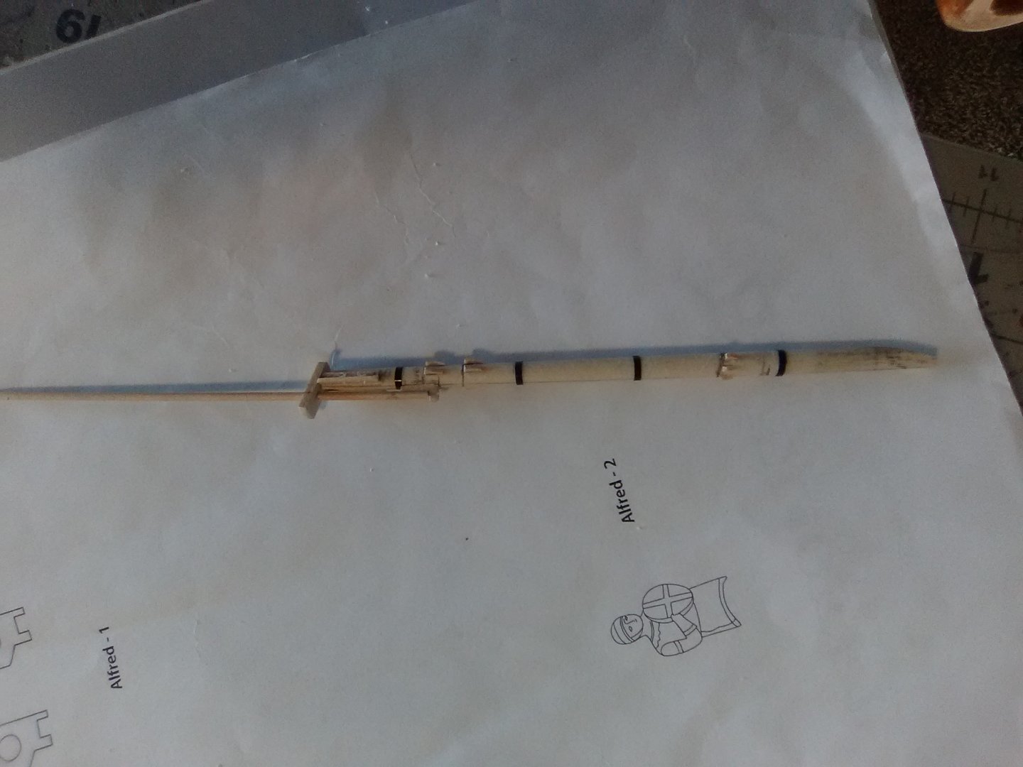
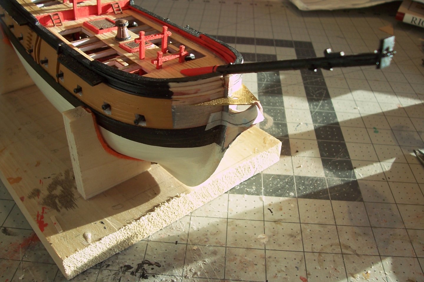
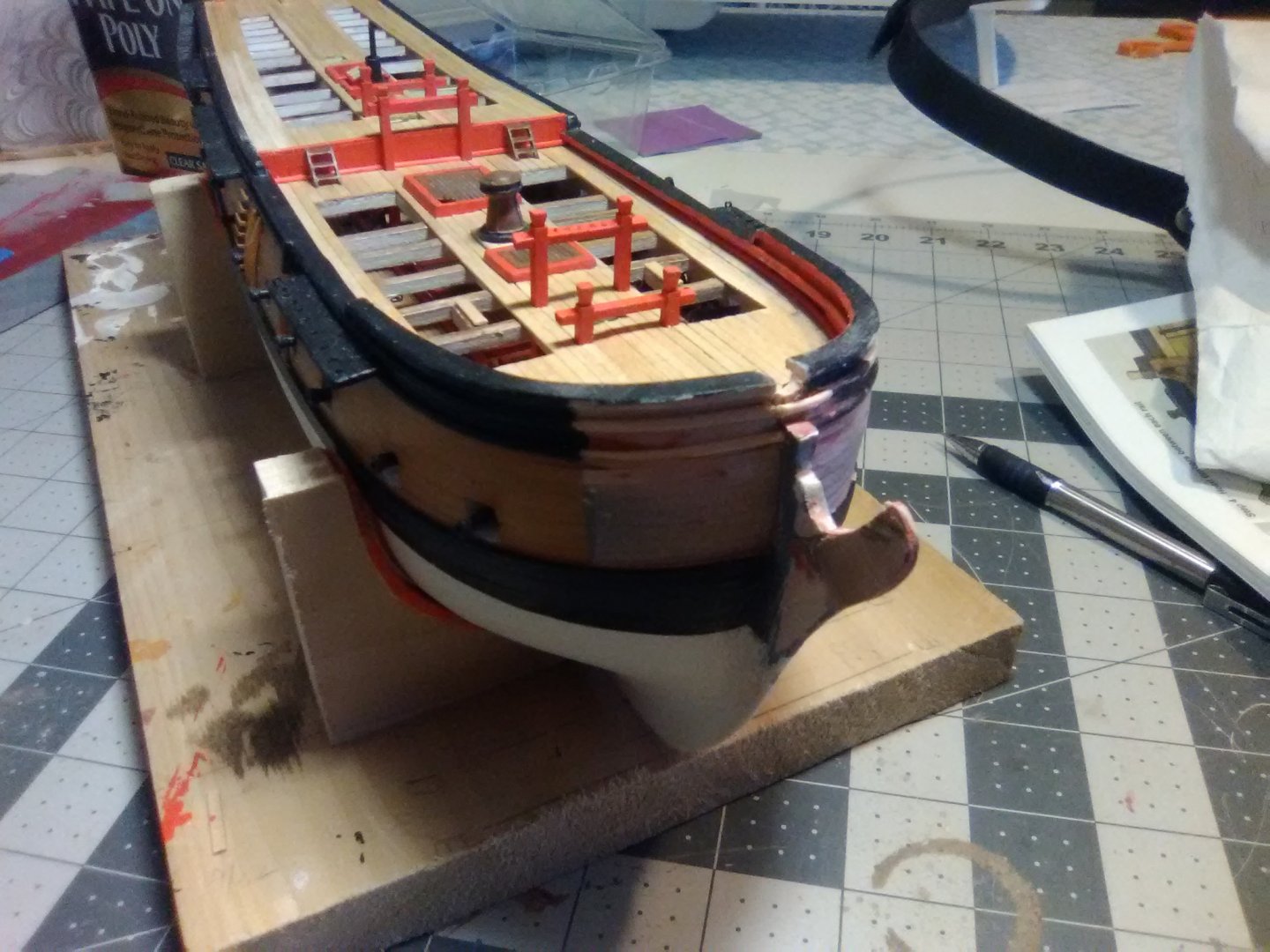
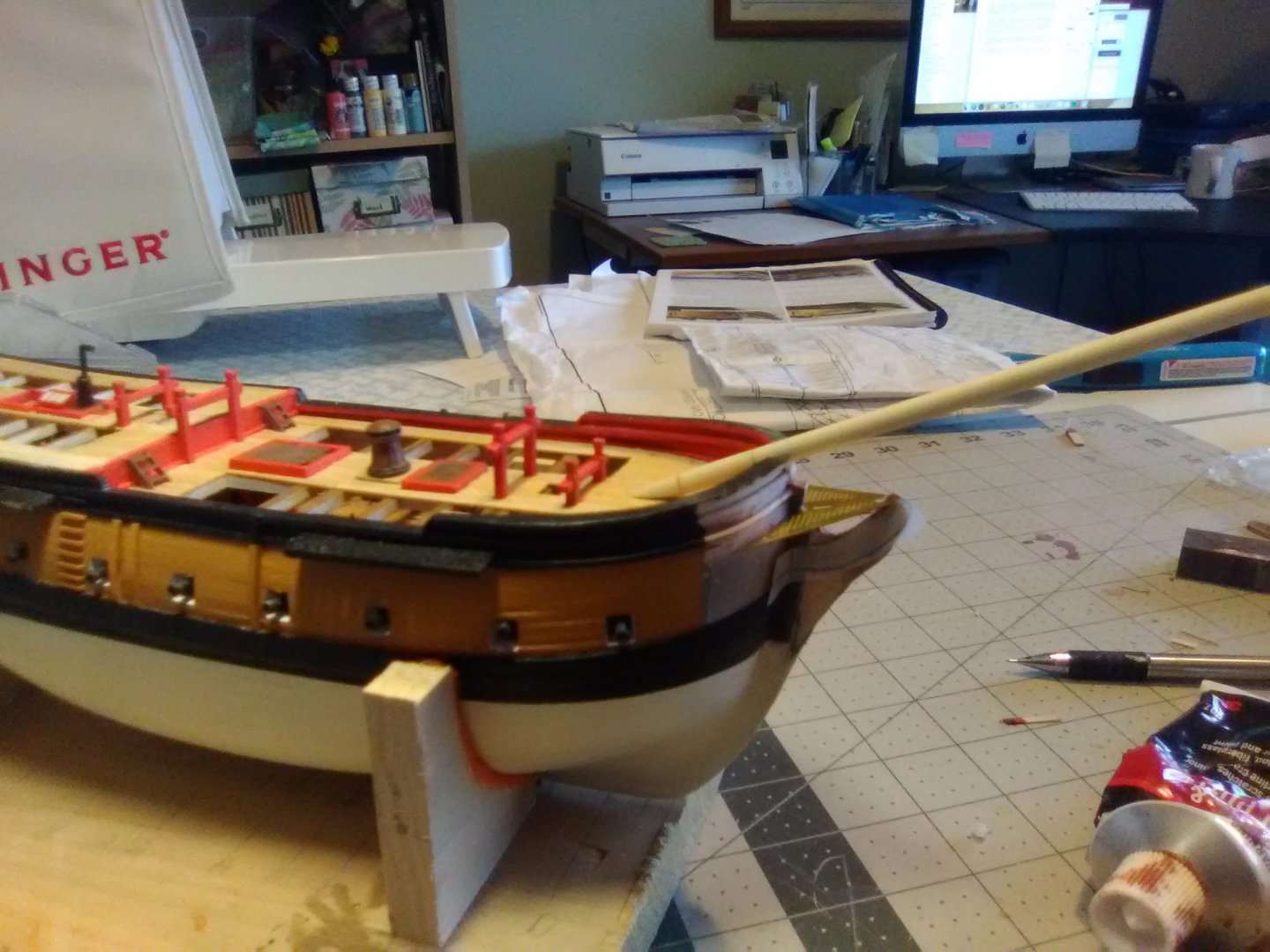
Bowsprit & Jib boom I finished up the bulwark area around the bowsprit by raising the stem to support it and then penciled in the locations for all the “stuff” that goes on the bowsprit. The height of the bowsprit cap is from the plans but I had to go to AOS Essex for the width, about 40% of the height is good: The instructions call for tapering the jib boom, which I did. I recommend skipping that step for 2 reasons; the tapering is not noticable on such a small dowel, and more importantly, the tapered end lost its' rigidity - it would have been a huge hassle trying to keep it straight while under tension from multiple directions, assumming it didn't break. I redid it without tapering. Here’s the completed bowsprit and jib boom: Here’s the bowsprit dry fitted in place. The paper you can see on the stem below it is a template I’m going to use to scratch the trailboards.
- 142 replies
-
- 6
-
-
- alfred
- solid hull
- (and 2 more)
-
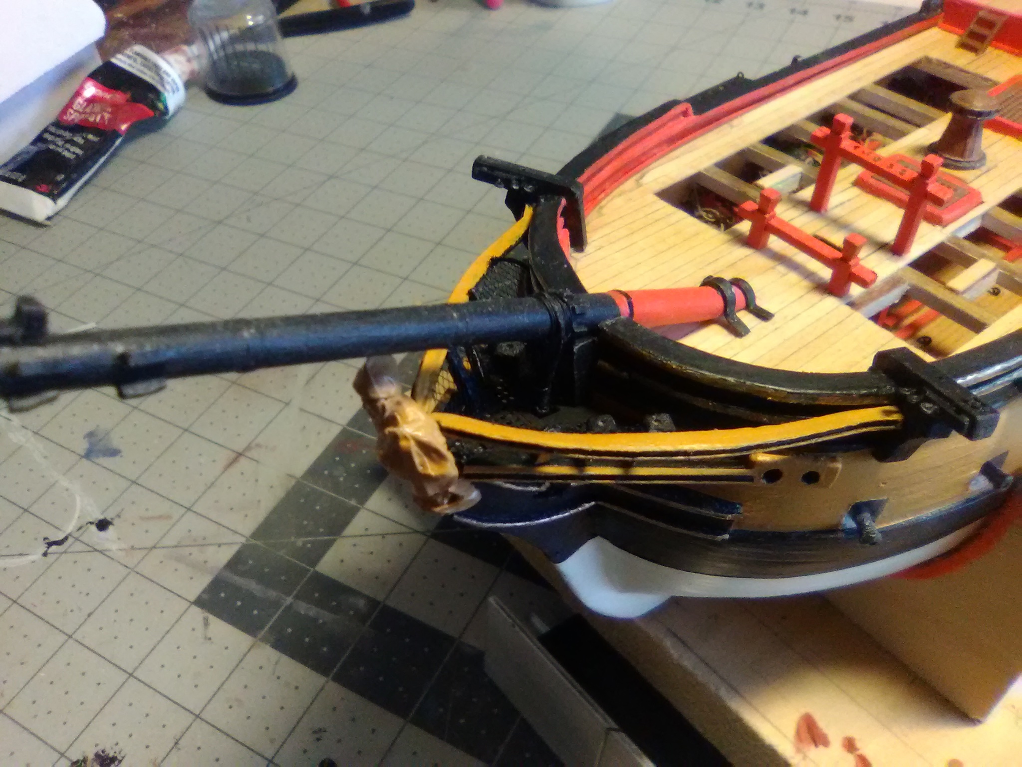
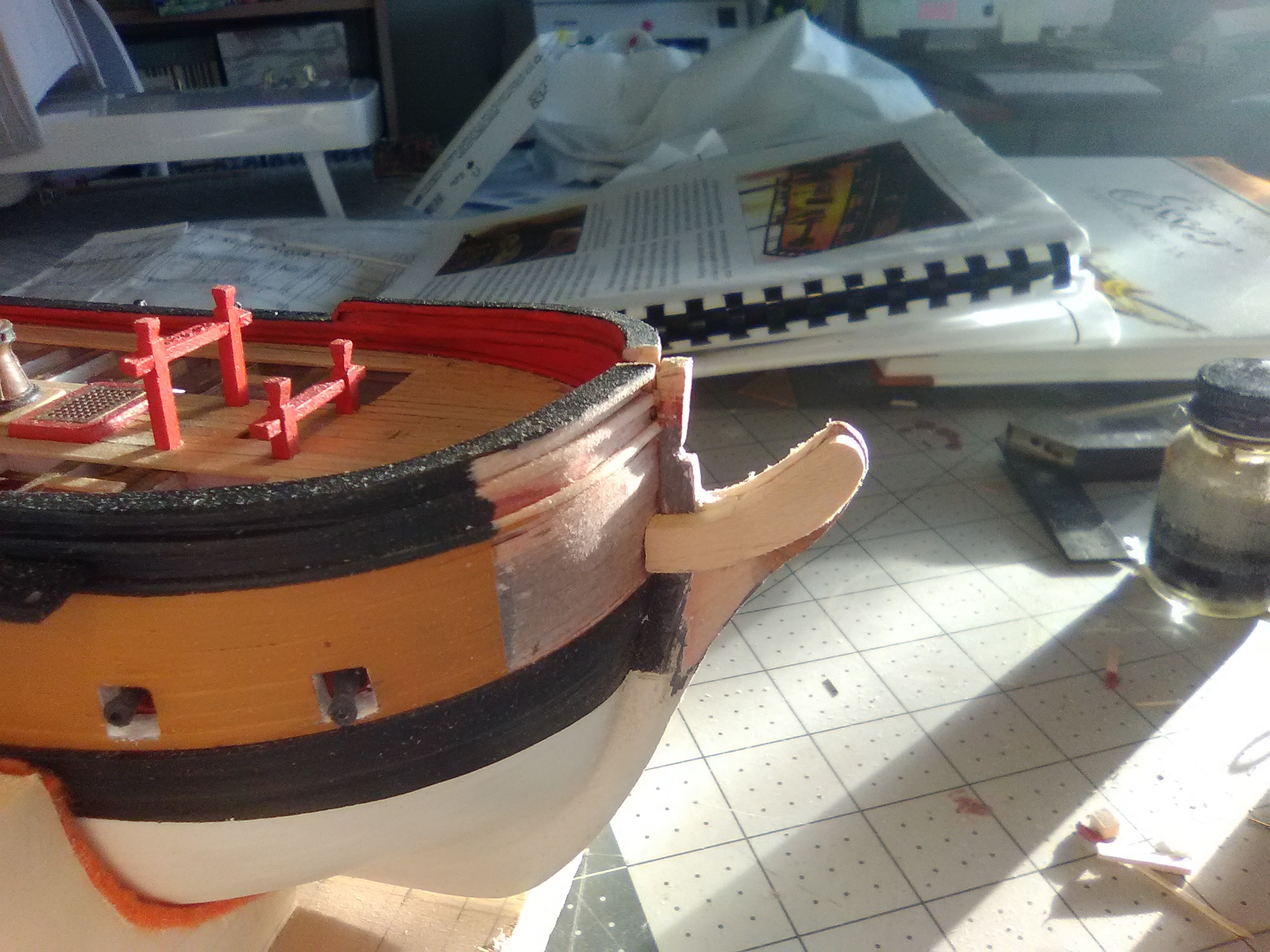
Things start to get complicated I thought my next step would be per the sequence laid out in the instructions, i.e. adding the details along the bulwarks working fore to aft, so I thought I would start with the catheads (the davits that the anchors hang from) but I ran into a problem that will take me in a different direction and hopefully not into a rathole. The problem is that the plans only show the catheads on the outboard profile (the side view of the ship) and since the catheads are located where the bow has it’s very bluff curve I could not figure out where they get placed (an overhead view would have solved this problem). After a lot of looking at the instructions, the plans, build logs of contemporary models and the instructions for ModelExpo’s SYREN, which are, hands-down, best set of instructions I have ever seen, I finally figured out that the catheads need to be above the hawse bolster (the holes where the anchor hawsers pass thru the hull), which in turn is part of the whole complicated head railing assembly. (BTW, the SYREN’s instructions are available online , as are the ones for all the ModelExpo kits on their website) After a lot more studying I think I understand how the head rails go together (every set of instructions I looked at said the head railings were the most difficult and complicated part of 18th century ship models) I realized I would have to tackle the head railings but before I could do that I needed to assemble the bowsprit for 3 reasons: 1) I want to rig the gammoning (a bunch of figure 8’s that lash the bowsprit to the hull) before adding the railings since it will be very difficult to do it after they are in place 2) I want to ensure that the gammoning is vertical which will depend on the slot in the stem the “hole” in the grating, and the chocks on the bowsprit, and 3) because I need to ensure that the figurehead, which although decorative is a key part of the head rail assembly, is not going to interfere with bowsprit which sits right above it. So bottom line: I’ll be departing from the build sequence in the instructions because of all the interrelationships of the “stuff” around the bow/stem I’m going to try to stay out of my own way and avoid bad language when finding out I should have done step 10 before step 2, so to speak. I’ll try do document each step and also what doesn’t work for those who may decide to try this kit. To get started on the bowsprit I had to do some plastic surgery where it will pass thru the bulwarks. When I added them I left a gap that needed filling at it’s bottom so the bowsprit will sit at the proper angle: I tapered the aft end of the bowsprit so it will sit properly (it, of course has not been cut to length yet) I also filled in the gammoning slot which had been cut in the stem early on since I will have to drill out a new one based on where the head rail grating sits. You can slo see a paper template for the the tailboards which I plan on making from scratch so they will be a better fit for my stem that the kit-provided britannia pieces.
- 142 replies
-
- 5
-
-
- alfred
- solid hull
- (and 2 more)
-
Nice job cutting & filing - your seams look great (as does your smooth primer coat).
-
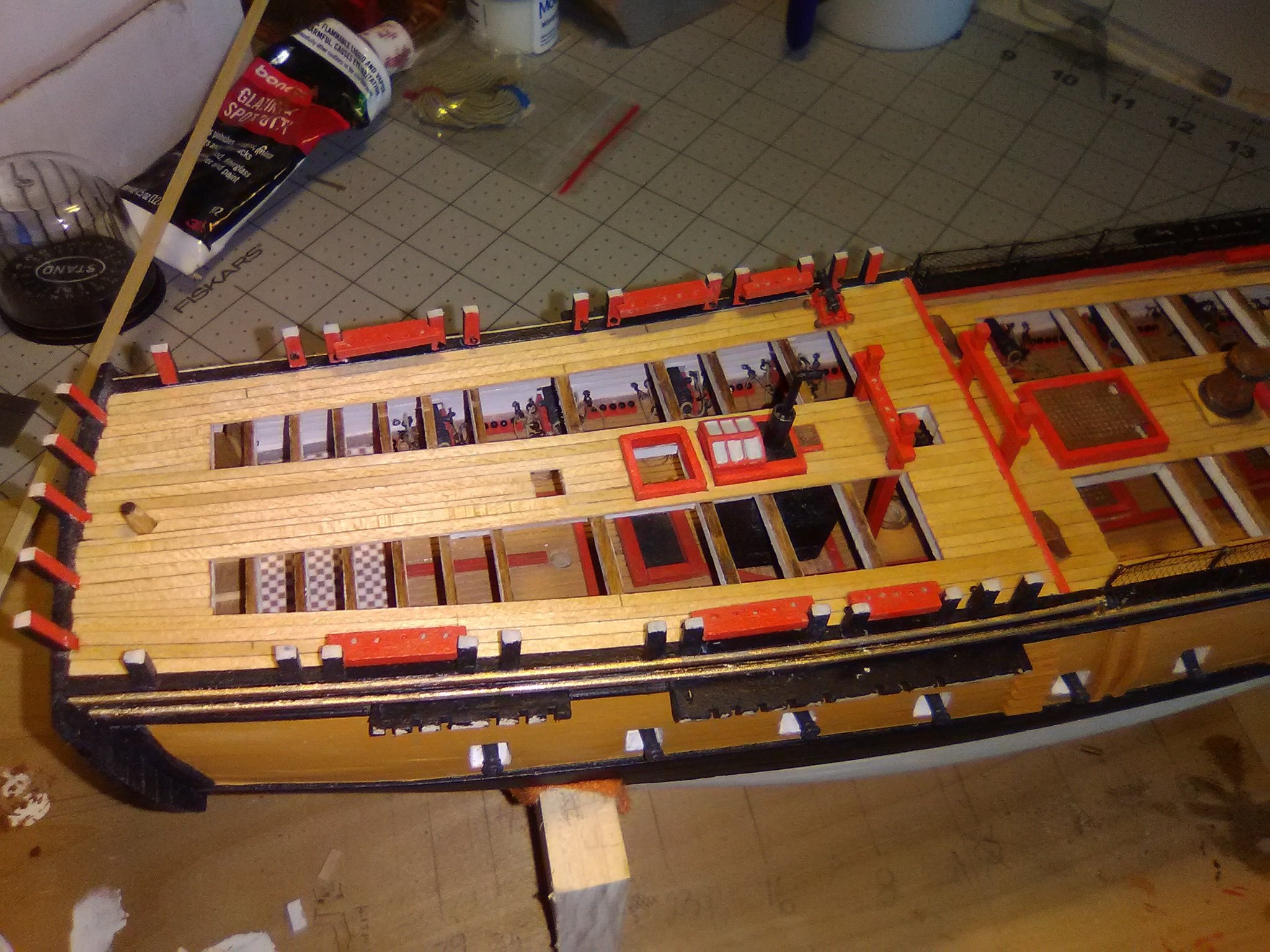
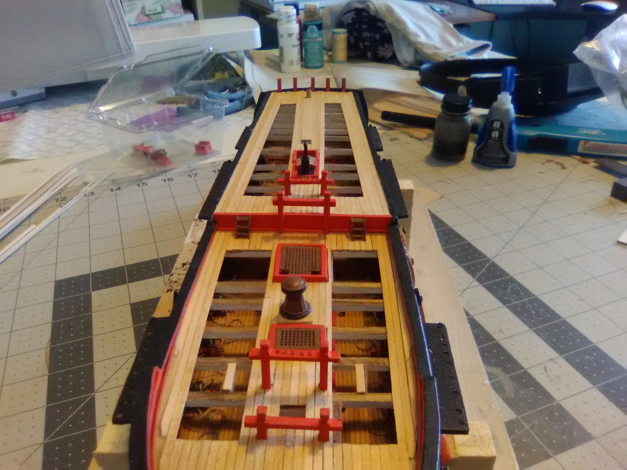
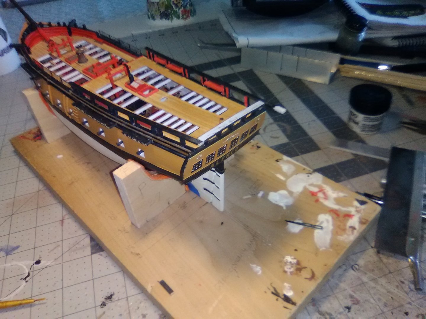
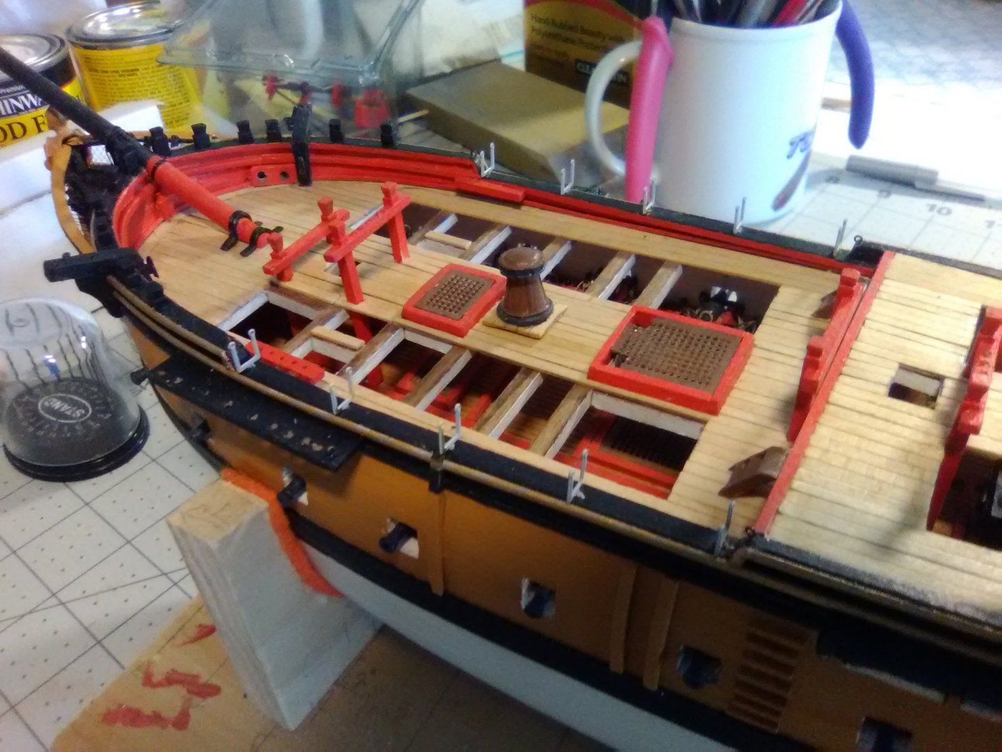
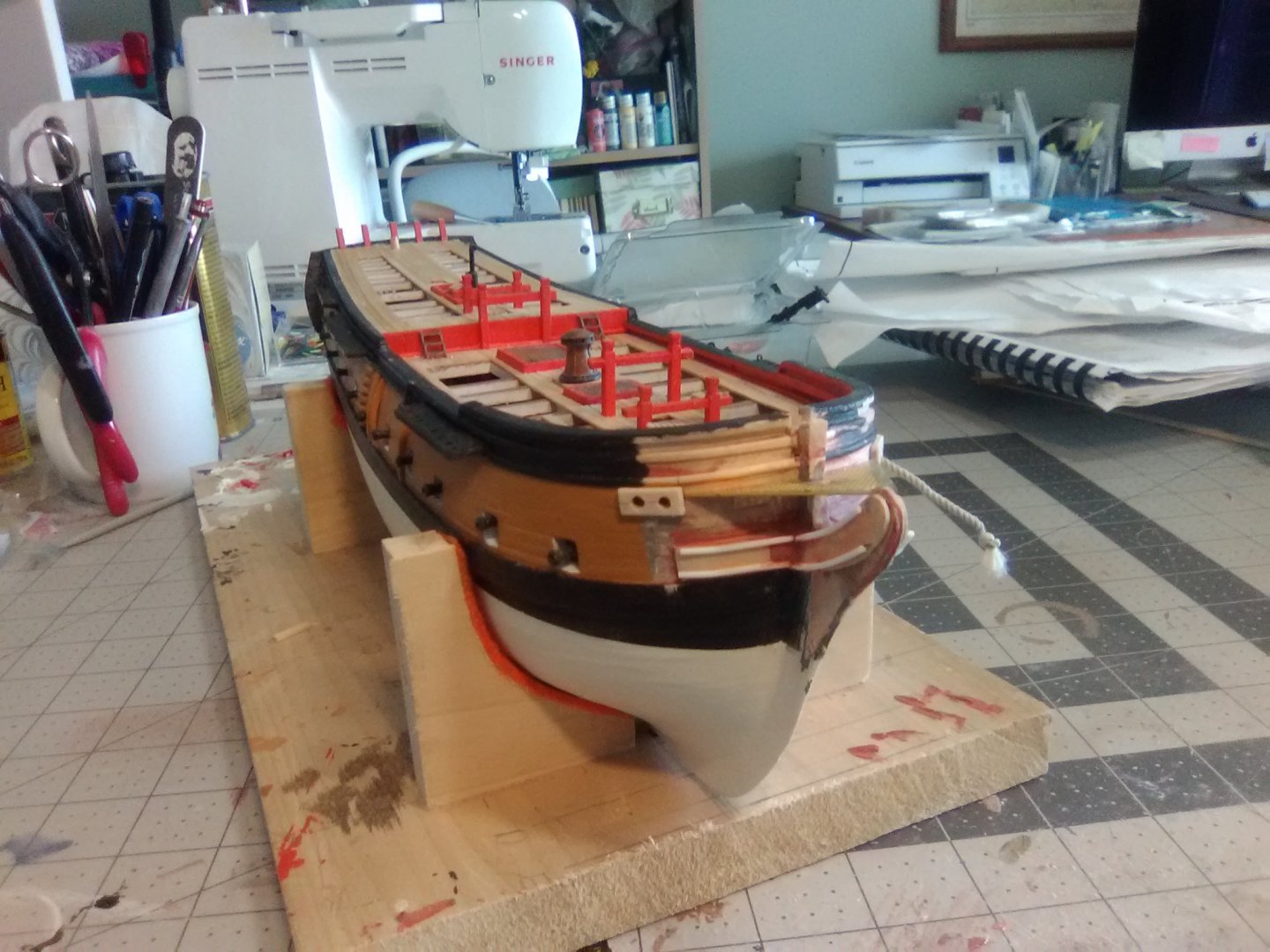
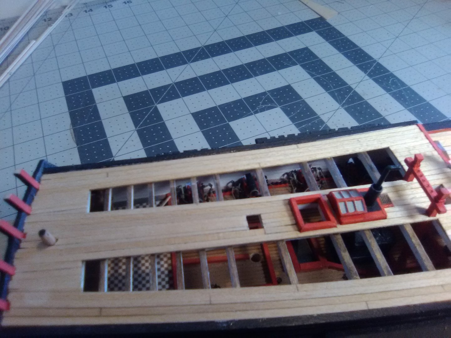
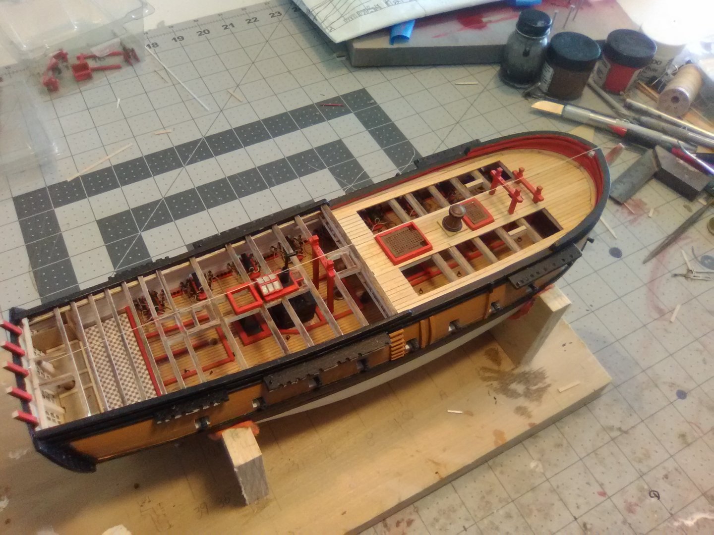
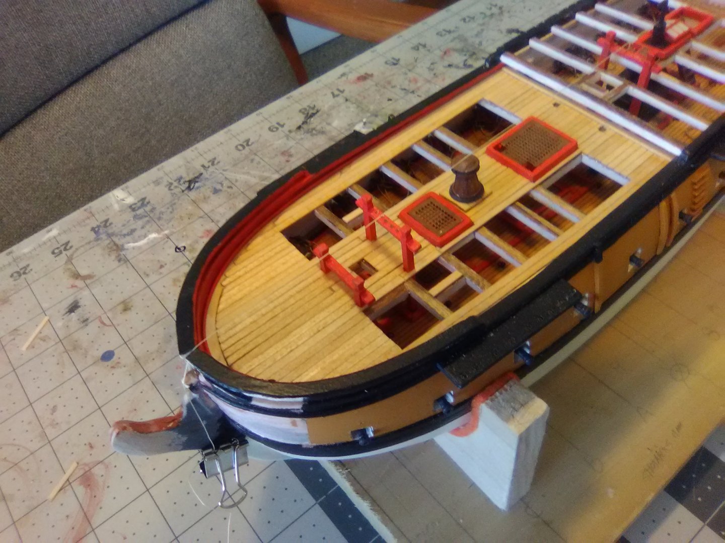
Deck Planking Finished The instructions call for making the vertical bulkhead at the aft end of the main deck from the scribed decking material but I thought that would be a hassle trying to get a good fit at the outboard ends so I used planking strips placed vertically and topped with another strip that covered the ends and served as a flush piece for the quarterdeck planks to but up against. The quarterdeck planking went on without any problems and the reveals provide decent visibility down into the gun deck.

- 142 replies
-
- 7
-
-
- alfred
- solid hull
- (and 2 more)
-
Avi, I have not built the Connie but I am building BlueJacket's ALFRED and I seem to recall the same issue with where to set the profile around the stern. I think your blue line might be correct because that is where the bulwarks end but when you get around to adding the transom it will be convex (bending aft) and it's center line will reach the red line. Bottom line - no need to cut to the blue line just now, wait until you hear from some folks with experience on this kit. You can always shorten the bulwarks later but it would be harder to lengthen them.
-
It's really hard to see any difference in the sponson locations based on the photos - especially with the flight deck on. That means it probably won't be obvious to anyone looking at the finished model. But if it bugs you, you could, as you said, relocate the sponsons but before you do that you might want to verify that the flight deck is parallel to the keel. Be careful - measurements like this are easy to screw up. You would need to make sure the hull is sitting on a flat surface (not a book), that it is level athwartship (i.e. not listing port or starboard) and then check the height of the flight deck (actually I mean the part of the hull that the flight deck sits on) along it's whole length. Using just a ruler and eyeball will likely give you some pretty unreliable data - you would need some sort of jig to run along the hull. Something like a high school football goal post with the crossbar held in place by clamps so it can be adjusted might do the trick. You could set it so the uprights stradle the hull and the crossbar just touches the forward edge of the deck and then move it aft - you will be able to see if the height is constant. If you think you have a problem you should come up with another way of checking it and verify there really is a problem before you do any sanding. As I said at the start, just based on your photos I think you are OK now.
- 25 replies
-
- 4
-
-
- Gambier Bay
- BlueJacket Shipcrafters
- (and 1 more)
-
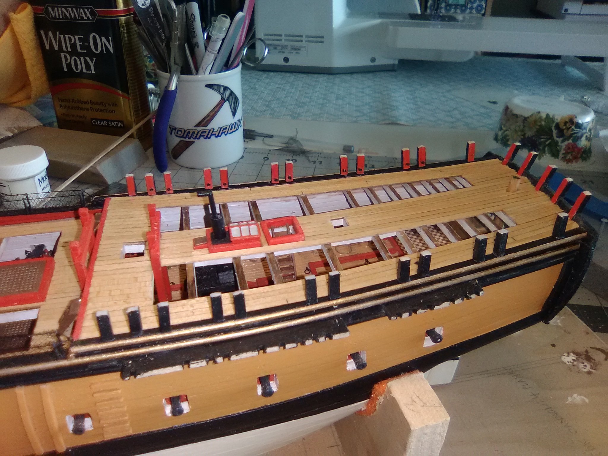
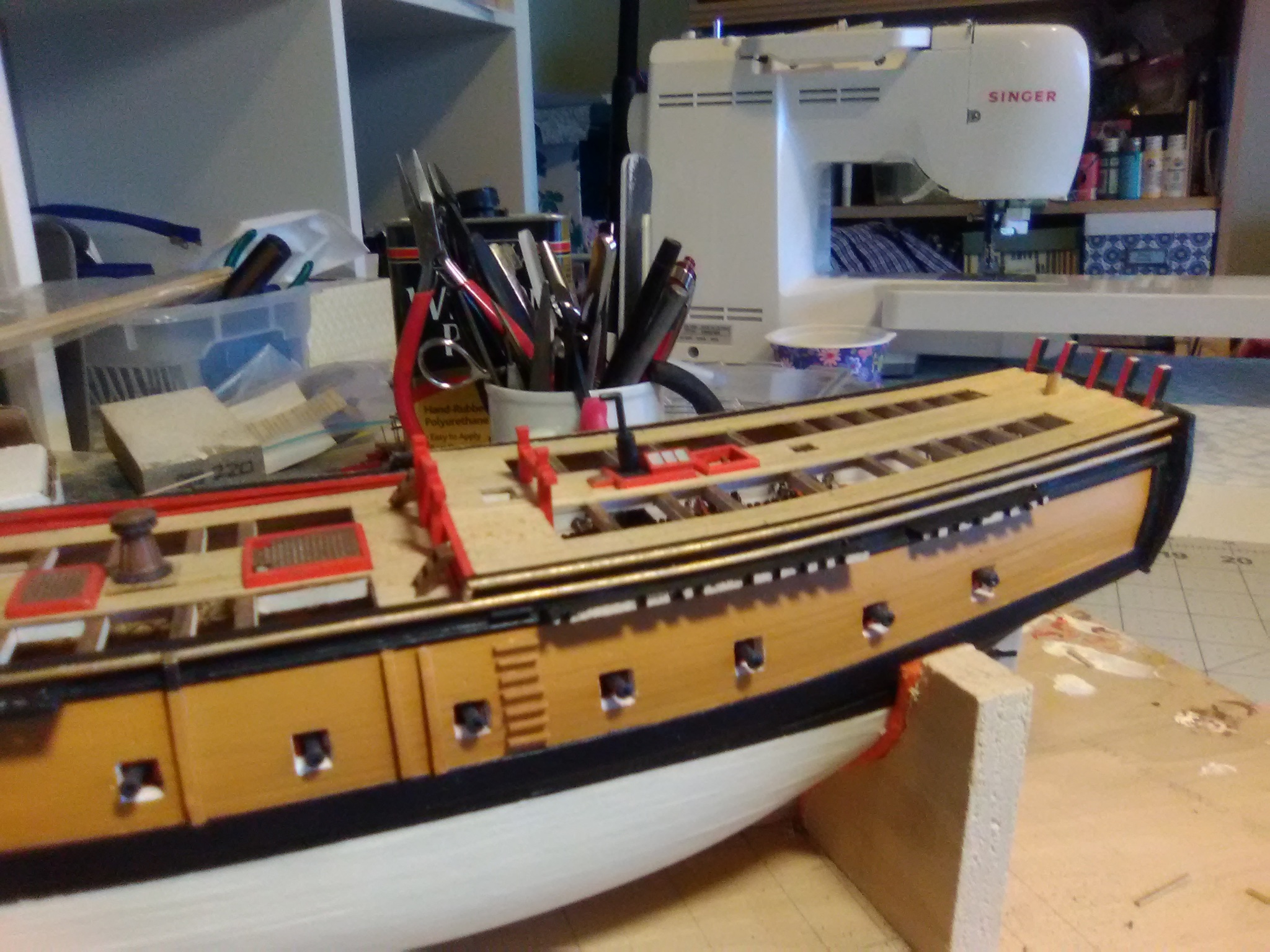
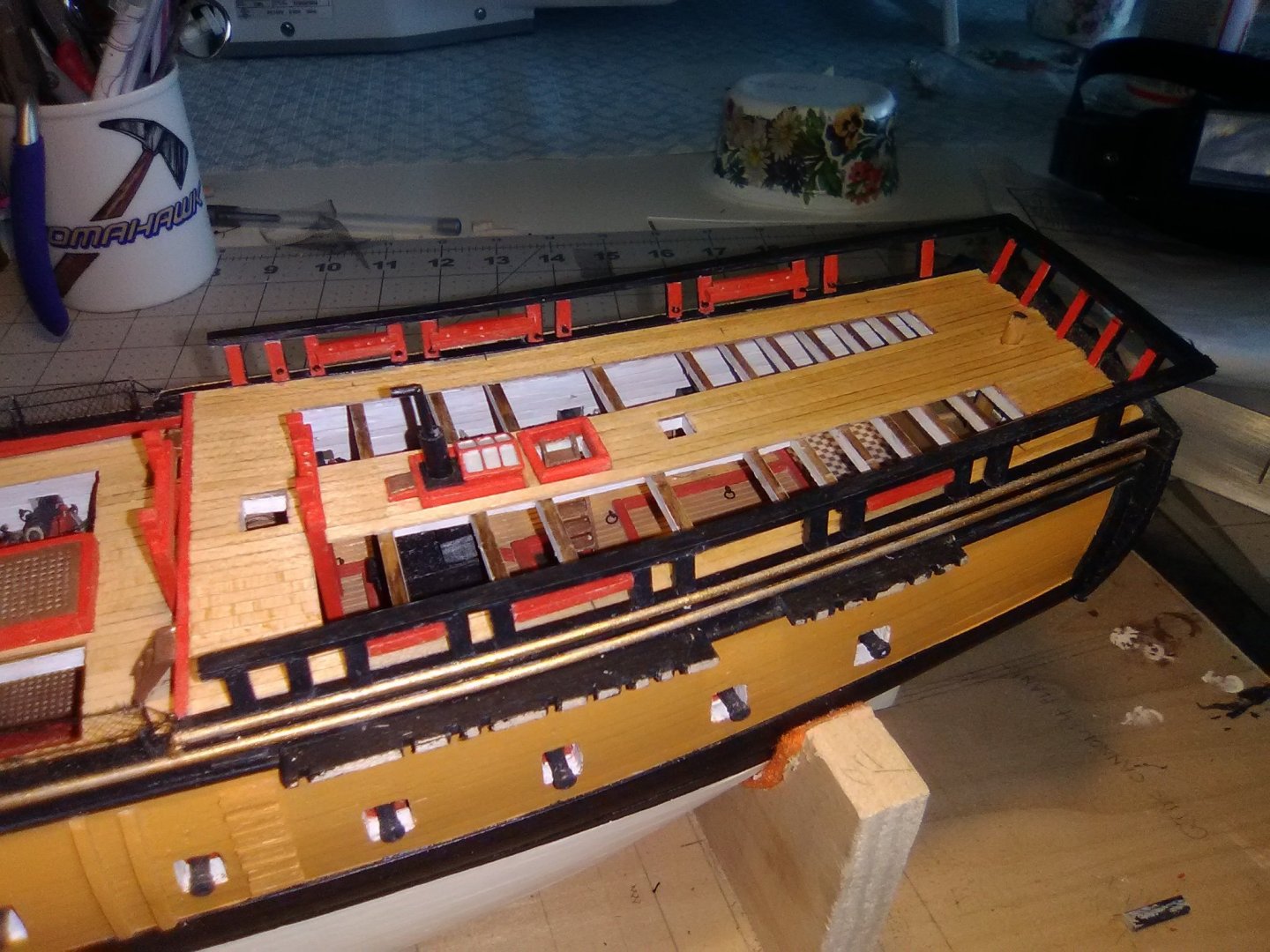
Main Deck planking completed The planking for the main deck is completed - I’ll wait until after it’s done on the quarterdeck before I clean all the saw dust out of the gun deck. Next up will be installing the short vertical bulkhead that divides the main deck from the quarterdeck.
- 142 replies
-
- 11
-
-

-
- alfred
- solid hull
- (and 2 more)
-
Good luck Avi! She is not an easy choice for a first build but as you have seen on the Connie build logs on here it can be done, and done well. Best advice I can give is go slooooow. Take each step as a project in itself and forget how much is left to do. If you measure 4 times and cut once you should be in good shape.