


wefalck
-
Posts
6,664 -
Joined
-
Last visited
Content Type
Profiles
Forums
Gallery
Events
Everything posted by wefalck
-
 You are holding down the model through a neodynium magnet, right ? Good idea. Nice model ! First I thought it was the old 1/32 scale Airfix kit.
 -
Love those later 19th century/early 20th century steam fire-engines ! I have a project in 1:90 scale on hold. Purchased the Preiser-kit some 25 years ago, but could never find out on what preserved engine it was based, probably something in a museum in southern Germany: https://www.maritima-et-mechanika.org/maritime/models/steamfireengine/steamfireengine.html. Whenever I came across a museum species, I took lots of pictures to better understand their mechanics. At steam-fairs and similar occassion I have seen some in operation. The most difficult task would be the coach-lining that was used in Europe at least frequently.
-
Somewhere in the depths of my picture analogue archive there must a couple of images of one on a country road in Hungary in the early 1970s. They were seen then and there occassionally. Here is a Wikipedia-page on the company: https://en.wikipedia.org/wiki/Velorex. There are also quite a few pictures on the Net and YouTube has videos with them. Didn't know there was a kit for it. Nice idea to present it in a sort of 'exploded' form !
-
What about the drawings or other sources the original modeller worked from ? There should be a reason, why these bits are placed so close to the hatch and why they are so high - both features are not really optimal from a mechanical and working point of view. Normally, you would place the axle of the windlass as close to the deck as you can, so that its fulcrum on the uprights is as short as possible.
-
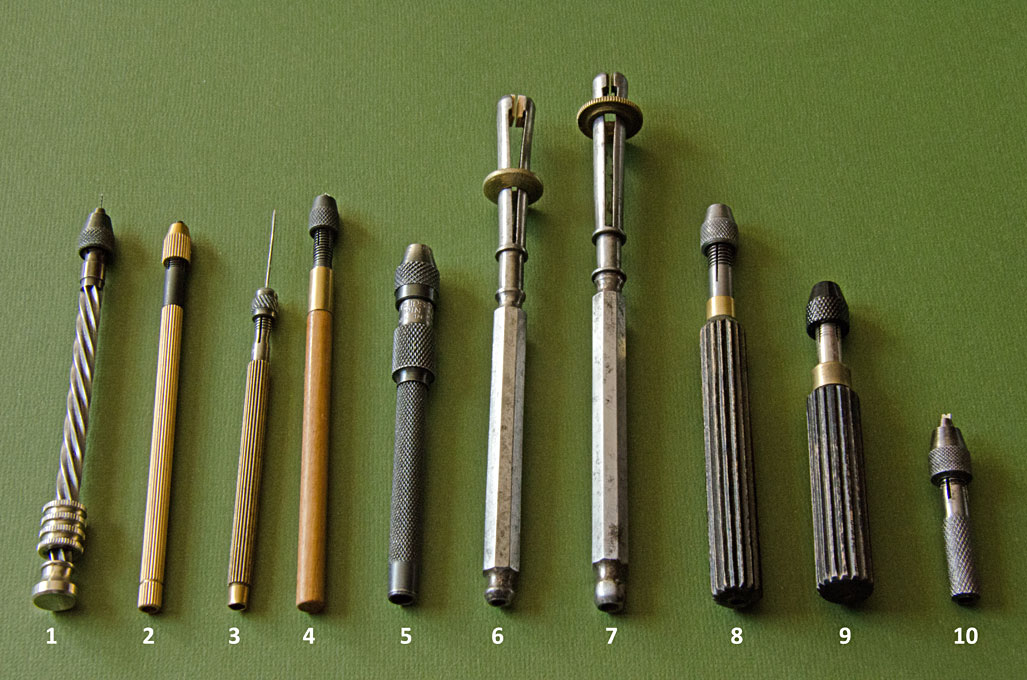
As you can see in my picture above, No. 1is an archimedes drill that closed down to virtually zero. I got it some 30+ years ago from the local watchmaking supply store in Nottingham/UK. For such products Internet-buys can be problematic, as you cannot check how well it is really made. This drills are also made in a 'double-action' version with spring-return. The Starret/Eclipse toolmakers pin-vices are very good for their purpose. For work on models with various inserts they are often too bulky. For this I prefer slender ones as No. 2 or 3 above. It is always good to have a selection of types, as there is no all-purpose one.
-
Indeed, such washings tend to pull and blend things together, creating a visual unity and depth of relief. I would rather doubt, that silver was used on a real ship (it would work for a model), as in the presence of sulfate-sulfur in the seawater it would probably tarnish rather quickly and become black. If a silvery effect was desired, they could have used ground and burnished on mica (muscovite, the stuff that was also used as heat-proof glass-panes in lamps or for windows).
- 2,699 replies
-
- 5
-

-
- heller
- soleil royal
- (and 9 more)
-
However, soil scientists still think that steam-ploughing was better for the fertility of the soil, as going over the soil with heavy machinery compacts it increasingly, thus reducing its water retention capacity (the hydrologists call this field capacity) ...
-
I think they operated with a crew of 4: 2 drivers on the engines, 2 men on the balance-plough. In addition, the farmer/landowner had to provide a few hands to move the trolleys with which the idle cable was kept off the ground and a horse with driver to be harnessed to the water-cart that supplied the engines with boiler feed-water. He normally also had to supply the coal for the engines, I think. These ploughing teams would go across the country, one engine towing the plough and the other the living-van and the water-cart, the latter two also supplied by the engine manufacturers. There is a 1970 book that describes the 'business' and some of the folklore around it: HAINING, J., TYLER, C. (1970): Ploughing by Steam.- 360 p., Hemel Hempstead (Model & Allied Publications Ltd.). In those pre-Covid days there were often steam-ploughing demonstrations at the big steam-fairs, such as the one in Dorset: https://www.gdsf.co.uk
-
One has to distinguish also between what a real ship would have looked like at the time and how we today depict them. Fashion has always been an important factor, but also technological constraints. 'druxey' gave already a comprehensive overview to which I would like to add a couple of point: - The price of pigment is determined by the raw material and the cost of converting this into a pigment ready for use; most pigments used outdoors and on ships are minerals, which had to be refined and ground to a very fine powder; It was not until the later 17th when pigment mills driven by water-wheel or windmill (in the Netherlands) came into use, allowing larger quantities of good quality pigment to be produced, bringing down the cost of paints; as a consequence, larger areas of ships become painted since then. - Soot as a black pigment does not need to be ground down, so has been available for a long time. - Paint seems to have appeared on warships first, were cost is of less concern (at least to those, who ordered them, but perhaps not the tax payers ...), than on merchant vessels; merchant vessels begin to be painted all over only from the second quarter or the 19th century on. - The fashion of painting merchant vessels (I am talking only about northern Europe here) in the 19th century seems to evolved from painting the wales (mainly black, but also white, green or blue) and some thicker planks only, with the rest scraped and oiled/coated in Stockholm tar to the inverse, where only one or more of the wales is scraped and oiled. In the later 19th hulls were mainly black, sometimes green and very occassionally white (requires a lot of maintenance, due to the dirty harbour waters). So, not painting ship models, or only their wales and inside bulwarks, is basically a fashion among modellers. Perhaps it came about to show off their craftsmanship in woodworking, but it is certainly not what real ships would have looked like in the 18th and 19th century. In any case, accentuating different parts (wales, coamings, stanchions, etc.) by using different coloured woods is entirely artisanal and has nothing to do with how the ships looked like (though different types of wood were used, of course, for different structural parts).
-
Antique crochet hooks are useful. It seems the really fine ones are not made anymore, since chrochet-lace mats have gone out of fashion (except in China and N-Korea it seems). I inherited a few. Otherwise check on flea-markets. I also found on a flea-market some antique eye(?)-surgery instruments, including a very fine lancet (scalpel), which is useful for cutting threads in confined spaces. Another useful, home-made, instrument is a long sewing needle with the eye cut off, so that only a short two-pronged fork remains; this is useful for holding down threads or manoeuvering them around; they can be held in either a slender pin-vice or you can make a custom handle from wood.
-
There are many different styles of pin-vices and some of them close to near zero (at least when new / not abused). Check out watchmaking supply houses and the notorious electronic bay. Here is an overview over my selection that was either inherited or purchased: 1 - Archimedes drill for watchmakers. 2 - Slender modern pin-vice with hollow fluted brass body. 3 - Slender antique pin-vice with hollow fluted brass body. 4 - Shop-made pin-vice with walnut handle and head made from an insert drill-chuck; these drill-chucks are unfit for their intended purpose as they usually do not run true. 5 - British Eclipse toolmaker's pin-vice with knurled steel body; these come in different sizes - similar to the USAmerican Starrett. 6 - French-style pin-vice; these are closed with the sliding ring and have usually brass inserts in the two jaws that can be adapted to special needs; 7 - Dito, here the jaws are replaced in hard-wood for delicate parts. 8 - Antique laboratory pin-vice with fluted wooden handle. 9 - Modern pin-vice with fluted wooden handle; these come in different sizes and capacities. 10 - Antique toolmaker's pin-vice for very delicate work in confined spaces or as handles for small files and reamers.
-
boom rigging on a ship's launch boat
wefalck replied to Peanut6's topic in Masting, rigging and sails
You probably would have a cleat on both sides, because the guy at the helm would always sit on the weather side to be able to look up the sails and to balance the boat with the other crew-members. -
It appears to be some sort of landing carriage - launches for landing-parties were armed with small guns in slide-carriages as amphibious artillery support. Their barrel could be transferred to landing carriages. Most designs where two- or three-wheeled, with the third wheel removable when in firing position. A wheelbarrow would be a good option for operation on narrow tracks. At that time the Dutch were busy carving out a colony in SE Asia in the wake of the faltering VOC, an area probably with not too many roads, even by European early 19th century standards. If you are on uneven terrain, you would not push the wheelbarrow, but rather pull it. On the other hand, there are also two eyebolts at the front of the wheelbarrow, so that towing ropes could be attached for one or more men pulling on each of them - which was a common practice in civil engineering and mining. The man at the handles would mainly need to lift and balance it. As the centre of gravity of the gun would be more or less above the axle, when lifted up, it would not be a too heavy load for a single man with say a 3 pounder gun. The Chinese wheelbarrows for over-land transport had much larger wheels, which facilitates their movement over poor roads and paths. Also the loads were put onto both sides of the wheel, rather than on top of it, which lowers the centre of gravity. Due to its relatively large mass and diameter, the wheel would also balance to some degree the wheelbarrow by the gyrostatic effect. Wheelbarrows for transporting goods over long distances were sometimes equipped with sails to aid moving them along.
-
The Brits used armoured traction engines in the Boer Wars in the early 1900s and later during the early years of WW1. The problem with any kind of steam-engine in a war zone is, that even a direct hit with rifle bullet could lead to a catastrophic boiler explosion. The first use of traction engines in war I am aware of was during the Franco-German war of 1870/71. It was an experiment for towing supply waggons and also heavy siege artillery as the one used around Paris. I think the experiment was quite successful as such, but met with reservation from senior generals, who were used to horses. The railway on the other hand played a major role in the strategic planning. At that time the traction engine engineering was still in its infancy.
-
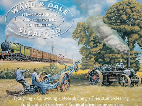
Thanks for the kind words on this 30+ year old effort of mine Here in Europe the term 'tractor' seems to be used only for IC-engine powered tractors, otherwise they are 'traction engines'. However, this is not a 'tractor', but rather a 'ploughing engine' as it does not pull the plough across the field directly, but rather by cable and winding drum: From: http://fumtools.co.uk/product/ploughing-engine-and-steam-traction-engine-jumbo-fridge-magnet/: And yes, the torque these engines can excert depends on the psi in the boiler and the cross-section of the cylinder(s) and not on rpms, which is why they survived for certain high-power applications (such as the deep-ploughing mentioned above) into the 1960s.
-
Yes, I meant holding while carving ...
-
You are getting better, Mark, practice helps. How do you fix the parts during carving ?
-
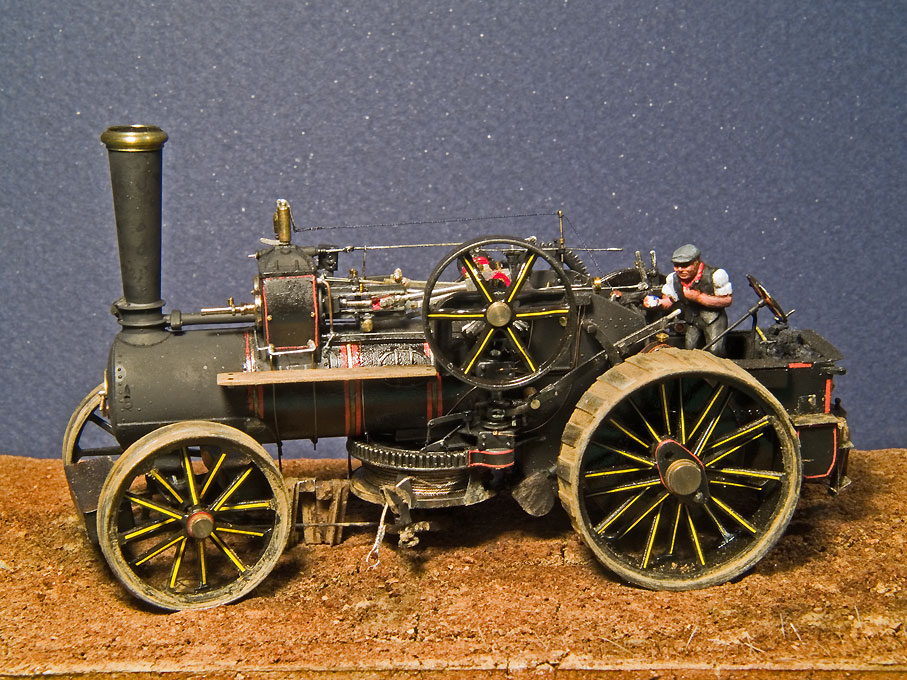
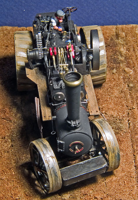
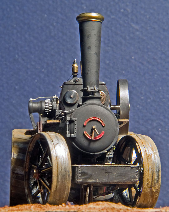
Well, the driver has his tea-break with his emaille-mug, if you look carefully The class Z7 was about the second biggest Fowler made. Their biggest was the Superba - several of them were ordered by the Mussolini-government to drain the Pontinian swamps south of Rome to get rid of the Malaria problem that plagued the city every summer. I think some of the German sets that were custom-build to drain the fen-lands (before they were considered wetlands to be protected) in northern Germany and to allow peat extraction. After the peat was extracted, the remaining moorland was deep-ploughed with a single shear plough in one pass to a depth of five(!) meters. One of the ploughing engines and a plough have survived in the Emsland-Museum close to the Dutch border.
-
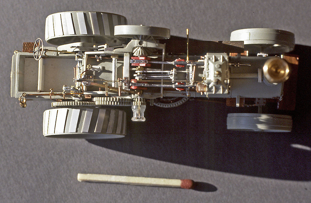
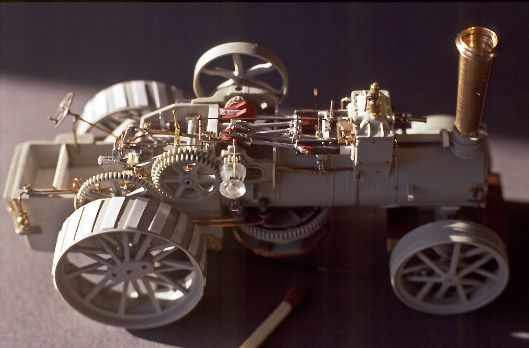
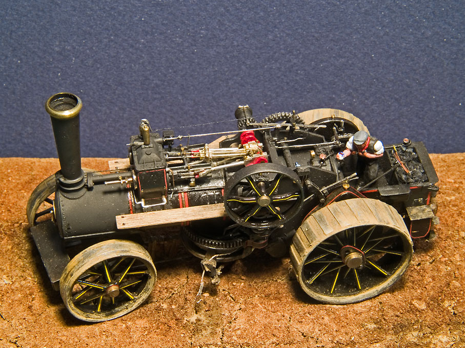
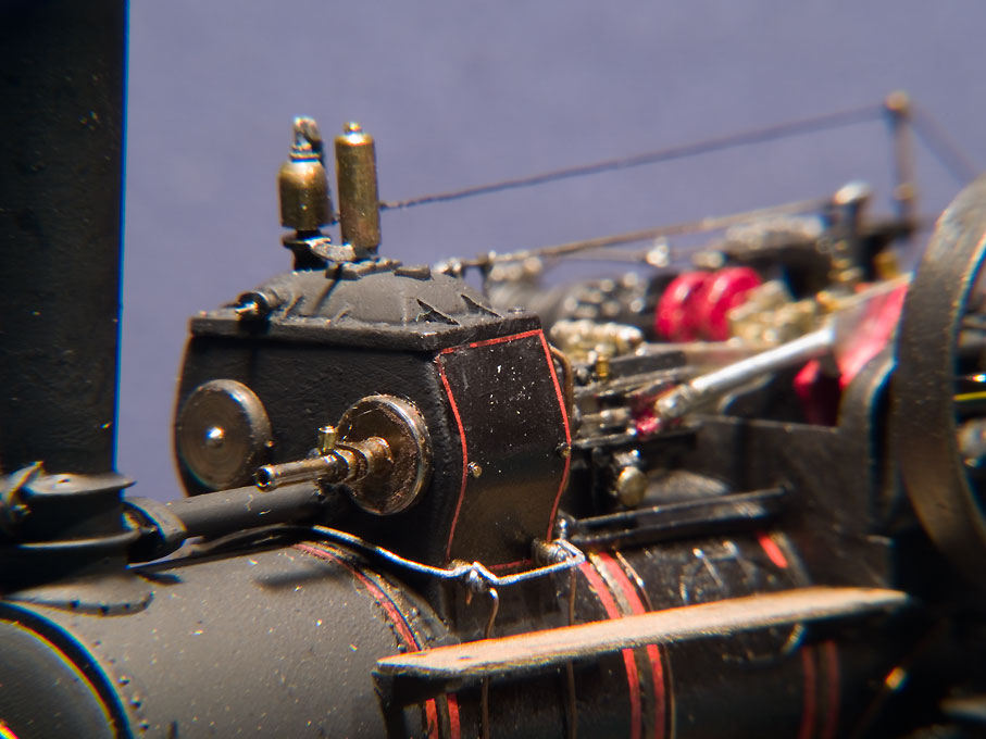
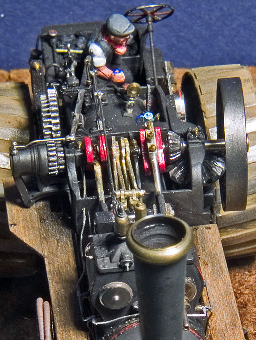
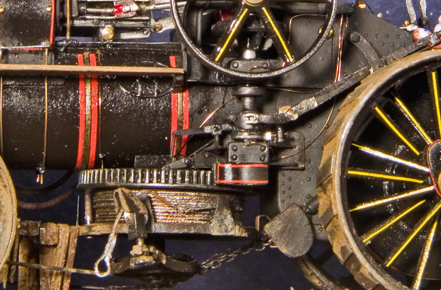
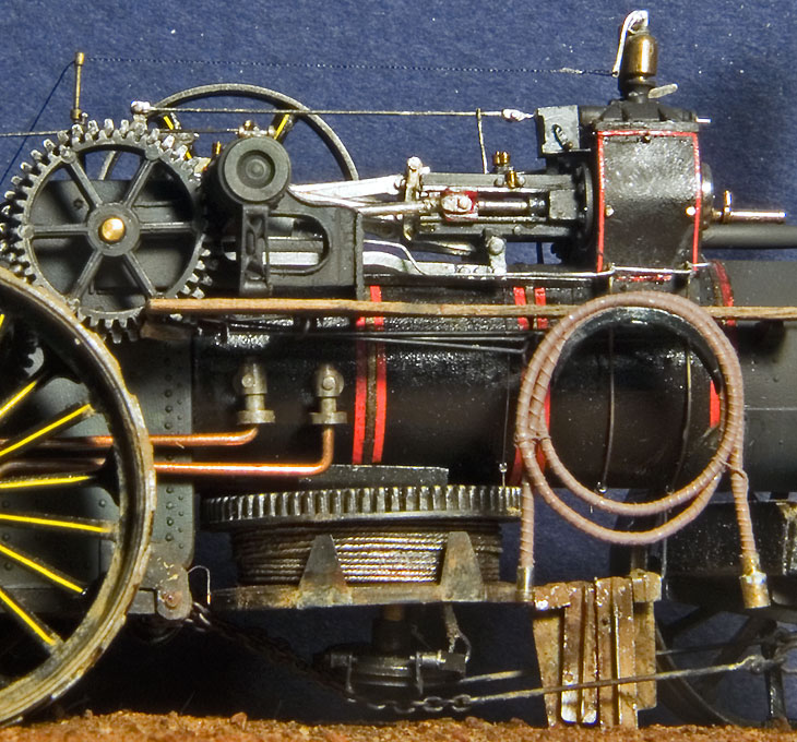
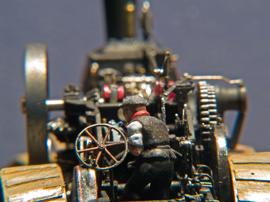
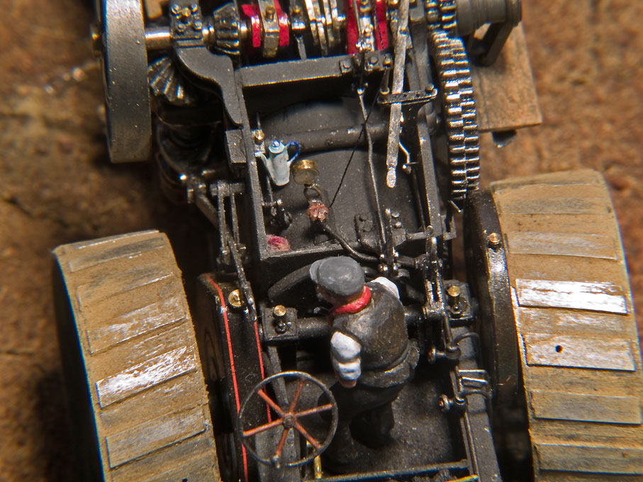
In the UK there is a real steam-engine scene, whole in continental Europe and much of the rest of the World these thingies may be only known as a historical phenomenon. Also, due to the industrial development lagging behind, they have not been as wide-spread, as in the UK. Having had the Matchbox model of a traction engine, I was aware of their existing from an early age on, even though I grew up in Germany, I certainly was not aware of the extensive 'steam scene' in the UK until I came to live there in 1987. I then attended various 'steam-fairs' and it turned out that the uncle of a colleague of mine actually had one ... This model was built around 1989/90. I just got my watchmakers lathe, but building a working model was certainly out of scope at that time. I happened to chance upon the Keil-Kraft kit, which was still current then - the company faltered since then. Just at that time the monthly Model Engineer published a series on building a working model of a Fowler Z7 (HAINING, J.: Countryman‘s Steam - Fowler Class Z7S.- Model Engineer, 5 August 1988 - 1 June 1990.), which came very handy for detail drawings, particularly for the actual steam-engine. A local museum owned a Fowler Class BB1 ploughing engine which I could photograph and sketch for more 'typical' Fowler details - the makers followed their design practices independent of the size of the engine. The visits to various steam-fairs furnished further photographs of Fowler engines. The assembled, but not yet painted model The Keil-Kraft kit was ok with respect to the proportions and the principal structure, but lacked most of the technical details that are very visible on such engines. Most notably, there was big hole, were the two-cylinder compound engine is supposed to be. So most of these details were built from scratch in brass, steel, aluminium, Plexiglas, and styrene. The engine, of course, is not working, but the appearance of the engine, the gearing, the ploughing gear, etc. has been faithfully reproduced as far as it is possible at 1:76 scale. Fowler was a very interesing and innovative company in the field and the market leader in steam-ploughing sets. A set consisted of two identical ploughing engines and a so-called balance-plough that was hauled between them across the field. The sets were expensive so that only very rich land-owners with large fields could afford them. Typically they were operated by contractors, who would move from farm to farm. Off-season they were employed in drainage work, pulling tree-stumps and everything, where a strong winding drum with a steel-cable was needed. The winding drum has an interesting history and was the key innovation by Fowler. The invention was not made by John Fowler himself, but by a young German engineer, who came to the UK to learn and in search of work. Max Eyth also became an important sales engineer, first helping the Viceroy of Egypt to build up a cotton industry and later in his home country from where he worked also in Eastern Europe. In Germany he also became known as a writer through his memoirs and various novels. Compound cyclinders with their drainage cocks, safety valve, and steam-operated whistle The history of Fowler as a company is written up here: LANE, M.R. (1980): The Story of the Steam Plough Works. Fowlers of Leeds.- 410 p., London (Northgate Publishing Co. Ltd.). Fowler not only produced plouging engines and ploughs, but also a wide range of traction engines, locomotives, and other items. The clutch-system to connect the winding drum to the steam-engine Two-speed driving gear and clutch and boiler-feed injectors including water-hose Driver's view Driving stand with all the levers, valves and gauges
- 32 replies
-
- 27
-

-
-

-
What Glue is Best for Rigging Ropes?
wefalck replied to Bill Jackson's topic in Masting, rigging and sails
I am using either shellac or something called zapon-varnish, which is similar to nail-varnish and is used tradtionally to varnish brass and silver aginst tarnishing. It is less brittle than shellac. The great advantage of such varnish is that it can be softened with a drop of acetone, so that one kan adjust knots or the belaying. If applied somewhat diluted, it is virtually invisible. -
Harriet McGregor by Boccherini
wefalck replied to Boccherini's topic in - Build logs for subjects built 1851 - 1900
How are you going to make the belaying pins ? I am going to have the same problem in the not too distant future - but an order of magnitude smaller I gues. What I have been thinking of, is to turn the belaying pins and their sockets in one piece - this safes me drilling the tiny (0.25 mm) holes for the pins. The belaying pin then will be cross-drilled half-way for the stems and the stems soldered in. Not sure, whether I can hard-solder such small parts with equipment without melting everything. -
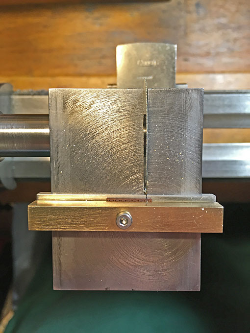
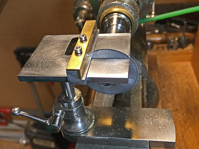
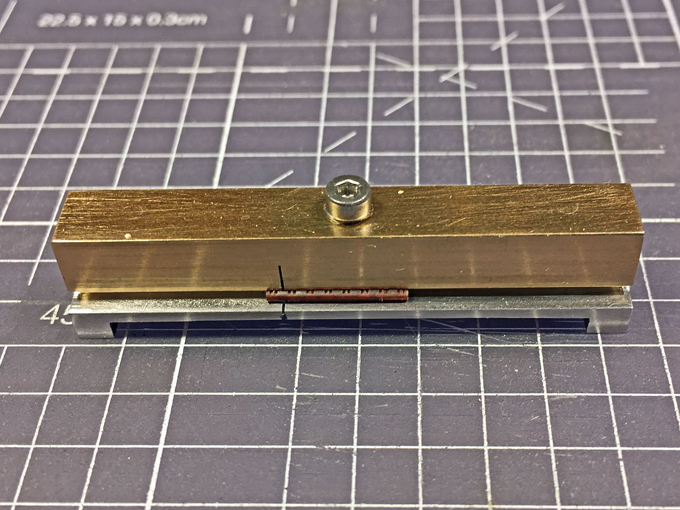
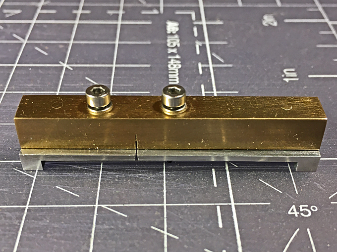
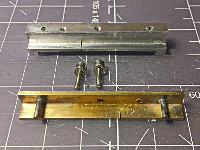
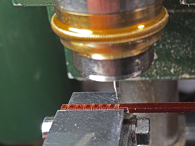
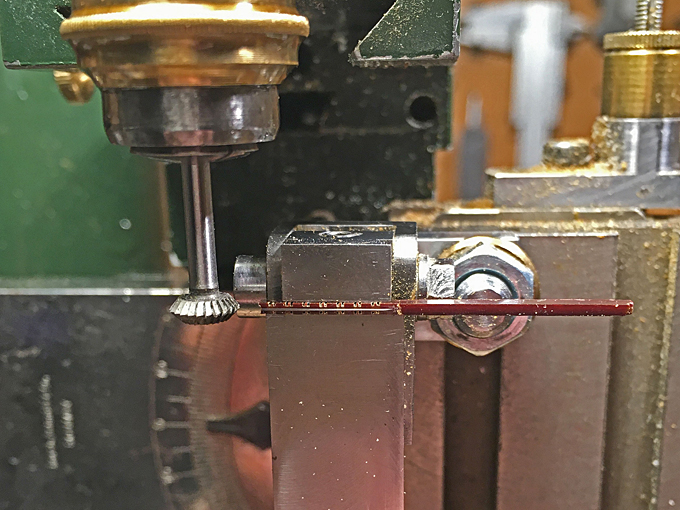
Sorry for the belated thank you for your kind words ! ********************************************* Block-making 2 Somehow it seems to be always two steps ahead and then at least one step back … apart from the actual manufacturing problems, I somehow loose about 30% of the originally made blocks somewhere along the road. They jump of the tweezers and other tools … and the bakelite being light and elastic they jump far away and never seem to stay on the bench or in my apron … I was not really entirely satisfied with the blocks I had turned out so far and tried out different variants of the above method over the past few weeks. Perhaps my improvised mill from a broken 0.2 mm drill was not sharp enough, anyway, the milled slots had a tendency to break out. I got myself from China (a lot cheaper than from European sources, where companies would have charged me for the shipping alone the amount of money that I paid for the item) a proper 0.2 mm end-mill, but the same happened. This is probably due to the fact that this kind of bakelite has a layered structure inherited from the paper that is used in its fabrication. Perhaps it would have been better to cut the block perpendicular to the layering. Cutting the grooves for the copper-wire straps I tried out a method that has been shown on various fora, namely saw cuts along the full length of the block to simulate the grooves for the sheave and then to drill a hole for the rope. The rest of the procedure was as above. Drilling the blocks with a 0.2 mm drill A problem was also cutting off the blocks from the billet. Somehow my method was tedious and at least about one in five blocks ended up flying around the workshop to be never found again. Not very efficient. So, I built a tiny gadget for the saw table of my lathe along the lines of the cross-cutting slides used on table-saws. This clamps the billet and the cut off block securely during the cutting and allows to locate the saw-cut precisely. A miniature cross-cutting slide for cutting off blocks from the billet It is a piece of rectangular aluminium 8 mm x 6 mm into which a recess is milled at the bottom so that it fits over the saw table and is guided parallel to it. Then a step is milled into the front, over which a 6 mm x 6 mm brass angle fits to serve as down-hold. The angle is guided by two pins that have been hard-soldered into it. Two screws (I have added a second one since taking the pictures) push the angle down onto the workpiece. The saw slot was cut in situ with the 0.2 mm wide saw-blade that I am going to use with the gadget. Now I can cut off the blocks safely and quickly without the risk of losing them. The cross-cutting slide used on the watchmakers lathe saw-table After separating, the blocks are shaped and rounded off individually using an abrasive wheel in the handheld drill. Earlier attempts with a small homemade tumbler were not successful, as the blocks are too small, too light, to few and the material too hard. Doing the rounding off in the hand-held vice works quite well. All the previous methods were aimed to efficiently round off the entrance to the borehole in order to simulate the sheave and thus to make the rope enter and leave tangentially to the sheave. In order to achieve this now, the rounding-off has to be done manually. Not so easy as the bore is only 0.2 mm. For diameters above 0.25 mm I purchased a diamond-studded round fret-saw blade, but this is the smallest diameter on the market. After some head-scratching I fashioned a micro-chisel from a broken fretsaw-blade, which is held in a pin-vice for the time being (have to make a graver handle). With the chisel the groove is rounded into the bore, while the rough block is held in the hand-vice that I have adapted for the purpose. The groove for the ‘iron’ straps were filed with a miniature (1 mm x 1 mm x 1mm) triangular file. Brass insert-jaws in the hand-vice, fashioned to hold blocks during manipulations The next challenge was the external strapping with a hook at the end. In theory, the straps are strips of flat iron bar. While it was possible to flatten the copper wire that I was going to use in controlled way, the material broke easily and it was difficult to place the flat sections before twisting the ends together to form the hooks. Therefore, a practical concession needed to be made and the straps were going to be round. The next issue was to hold the block while attaching the strap. I made a special clamp from Novotex for the third-hand, but it did not hold the block securely enough. In the end it occurred to me that also the hand-held vice could be used, while clamping it into a larger vice. Still the overall operation is very delicate. Finally, the tail end of the strap is cautiously bent into a hook. However, the copper wire is too soft to serve as a hook and also the structure of the two twisted ends is too obvious. Therefore, the hook was covered in a drop of soft-solder, which stiffens it and covers up to some extent the twisted structure. In addition, the back of the hook was somewhat flattened to better simulate the shape of a real hook. Overall, this is turned out to be a very time-consuming procedure and I reckon, that it takes me upward of an hour per block, adding up all the different steps, notwithstanding that they are made in small batches. That’s ok for a small ship, but would be out of question for a larger sailing ship. I am still not entirely happy with the fact that the blocks and in particular the hooks are not as uniform as I would have wished them to be. The lighter 2 mm blocks and the darker 1.6 mm long double blocks (they will be eventually all painted white) To be continued ....
- 935 replies
-
- 20
-
-
-
Ochre is a pigment widely used on ships of all times. Unfortunately, ochre is a complex mineral with varying properties depending on the source and its further treatment/refinement. Basically it is an iron-oxyhydroxide (FeOOH), but can be mixed with magnetite (Fe3O4), colloidal iron-hydroxide (Fe(OH)3), iron carbonate (FeCO3), and various other impurities, such as manganese compounds. In practice, the colour of natural occurences can vary from pale yellow to a blueish dark red. The more mineral water it contains, the paler the yellow and the less (in general) the more orange-red it appears. By heating it, one can make it deep red. Given this variability and the cost of refinement, since the middle of the 19th century the better quality is synthesised by precipating it from an iron solution, but the temperature variation still is there. In addition, ochre is rarely used by itself as pigment in paint preparation, but often diluted with some cheap white pigment - which changes it tint, particularly, if the pigment changes the pH of the paint, as e.g. ground limestone would do. The kind of binder used and any addition of driers will also change the tint of a paint - and glossy surface looks different from a satin or wheathered one ...
-
Just to add to Bob's comments: I have been using Vallejo et al. acrylic paints pre-diluted for airbrushing in such pens. As they come in bottles with pipettes, they are easy to adminster to the pens. Both, a curse and a blessing is the fact that acrylics dry very fast. So frequent cleaning of the pen is required, but that is easy. The typical draughting sets usually also include such pen-inserts for the various compasses, which could also be useful for making your own decals in this way. Earlier this year I also was able to buy cheaply one of those old-time gadgets with which one can generate broken lines - the pen is lifted and lowered by a toothed wheel as you run it along your ruler. Thought it might come handy for exactly that purpose or for generating rivet lines using a tailor-made toothed wheel and acrylic gel ... in fact the pens might come useful for generating welding seams as well, though I had not need yet to try this out.