


wefalck
-
Posts
6,644 -
Joined
-
Last visited
Content Type
Profiles
Forums
Gallery
Events
Everything posted by wefalck
-
 Sure they got hot when worked hard 🙃 Fraxinus excelsior L. (ash) was probably the most used species of wood in Europe, perhaps also Ulmus spec. (elm). In Northern America probably also hickory (Carya spec.)
- 433 replies
-
- 3
-

-

-
- open boat
- small boat
- (and 1 more)
-
I am sure there are many different patterns of oars, depending on the environment they are used in and how many men row on one oar. Sea-oars in general are symmetric, meaning there is not front or back and they are straight, i.e. the blades are not dished. Per stroke they are less efficient than inland-water or racing oars, but they are safer to handle in a sea. For this reason they are also fashioned from a single piece of wood, rather than having separate blades, as is common in inland-water oars. As there are no heavy blades, there is also less need to counter-balance them apart from the gradual increase in diameter towards the inboard end. Inland-water oars often are much thicker on the inboard end to counterbalance the longer reach and the heavier blade. Just to mention, these rationales apply to European-type craft, while in other regions of the world heavily counterbalanced sea-oars are seen.
- 433 replies
-
- 5
-
-
- open boat
- small boat
- (and 1 more)
-
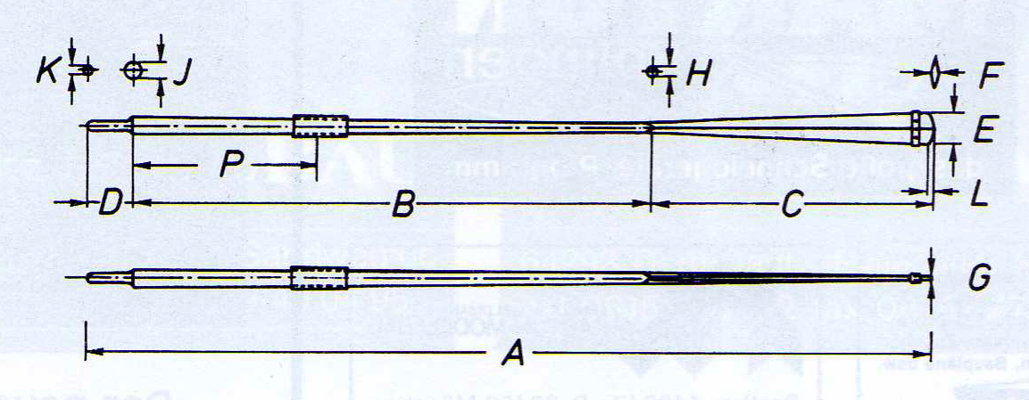
Just remembered that German colleague of mine wrote a three article series about the boat-oars used for the different types of boats used in the Imperial German navy. According to the contemporary sources the 8.5 m long cutter with 2.1 m beam and seven thwarts was equipped with the following oars: 12 oars in total of which 8 were type VI and 4 type VII. The dimension are then a per image: Type VI: A - 4250 mm, B - 2630 mm, C - 1400 mm, D - 220 mm, E - 140 mm, F - 16 mm, G - 8 mm, H - 43 mm, J - 65 mm, K - 40 mm, P - 815 mm and the leather cover 390 mm long. Type VII: A - 4000 mm, B - 2480 mm, C - 1400 mm, D - 220 mm, E - 140 mm, F - 16 mm, G - 8 mm, H - 43 mm, J - 65 mm, K - 40 mm, P - 815 mm and the leather cover 390 mm long. The longer oars are used towards the rear of the boat. So the oars have an overall length of around 13'11" and 13'2" respectively. The inboard end is about 41" and as there are two men on each oar they do not overlap in the middle, as they would for a single man on two oars.
- 433 replies
-
- 6
-
-
- open boat
- small boat
- (and 1 more)
-
Well, as others have said already, there is no such thing as a free lunch (or very rarely so). However, in my 35+ years of experience as (natural) scientific writer, peer-reviewer, corporate editor for an UN organisation and proof-reading editor for the German equivalent of the NRJ, I observe a change in the scientific publishing world. In the old days, when everything was printed, the publishing houses financed themselves through the subscription fees for their journals. Depending on the type of journal, for the most part subscriptions were taken out by (university) libraries or scientific institutions (through their respective libraries). To some degree, private individuals also took out subscriptions in order to have their private copies. For instance I had for several years subscriptions to Nature and Geochimica Cosmochimica Acta. The latter is published by the American Geochemical Society and part of the membership fee goes to financing the journal. The same system applies to many journals that are published by associations, e.g. NRJ or our German LOGBUCH. Journals also offered extra copies of their articles to authors as separate bindings against a (sometimes quite hefty) fee. Over here in Europe, universities and research institutions are usually funded by tax payers' money, so it us all, who finance the publication of scientific journals. This means the cost are distributed over millions of people so that the scientific world has this tool of exchange of knowledge. It is is a kind of mutualisation, as eventually the whole society will profit in one way or the other from the knowledge generated. Over the past three decades or so there has been a game change in the scientific publishing world and it has become more like 'real' commercial publishing houses, with increasing pressure to increase returns on investment, while some of the university-run publishing houses may have run on cost-covering margins only. This of course led to an increase of subscription fees. One should think that the transition to e-publishing with no printing, binding and mailing costs the subscription fees should have gone down, but that does not seem to be the case. In fact many journals started to charge the authors fees for publishing their work, while in the past this was mostly free or you had to pay only for fancy extras (e.g. colour photographs). As the funding for public institutions in the wake of Reagonomics/Thatcherism and due to shifting societal priorities was gone down, many (university) libraries had to become very selective with respect ot journal subscriptions. This made access to some journals or for people at smaller institutions difficult. However, there was/is always the option for distance loans or reprints of articles that these libraries offered for only a nominal fee. To counteract this problem, the European Commission requires from all its participants in research projects funded by them, that the work is either published in free-access journals or that you budget-in the cost of publishing in some high-flying journals. Peer-review is the traditional quality assurance mechanism in science. It is done on a sort of tit-for-tat basis, assuming that the whole scientific community participates in it: you invest your time in reviewing a paper, while your colleagues invested their time to review your papers. While it is normally anonymously to help towards impartiality and avoid bad feelings between individuals, it is also a way to improve your standing in the scientific world. And it is a way of learning and gaining knowledge before everyone else. However, the system now becomes a bit undermined by obscure on-line publishing houses, who charge everyone, authors and readers, but expect the peer-review to be carried out for free - I frequently get such requests from Asia ... Finally to the access to 'old' information. Of course, anything on which there is no copyright anymore is in principle free to access and use. However, the instiutions that hold this information (books, photographs, drawings, works of art, etc.) have costs and it costs them money to give you access to it. So it is understandable, that they have to charge you a fee in order to cover these costs. Again here comes the problem of diminishing funding for public institutions. While in the past this was seen as a common good and service to the whole society that in consequence was paid out of taxes, since the 1980s the paradigm shifted towards the idea that the 'actual' users should pay - which resulted in exorbitant fees (compare the pre-1985 fees for copies form the NMM in Greewich with todays fees ...), making this information rather difficult access. And then there are also those black sheep who exploit the laziness or ignorance of people by garnering information for free and trying to sell it. There is nothing wrong with companies that do information collection for you against a fee, but often they then pretend that they hold the copyright ...
-
Sherline Mill Essential Accessories?
wefalck replied to Some Idea's topic in Modeling tools and Workshop Equipment
This looks re-assuring. -
Just checked against my more or less contemporary sources - there is a textbook on German (naval) boats that was first published in 1878 and then subsequently re-edited about every four years until 1929 (I have all issues either as hardcopies or ebooks). The '22nd class cutter' is of comparable dimensions, i.e. 8.5 m long between the perpendiculars and 2.1 m beam. It has seven rowing thwarts and the complement is given as 35 rowers and other numbers, which seems to imply four rowers per thwart - indeed rather crowded.
- 433 replies
-
- 6
-
-
- open boat
- small boat
- (and 1 more)
-
Sherline Mill Essential Accessories?
wefalck replied to Some Idea's topic in Modeling tools and Workshop Equipment
The price/quality relationship of the Sherline 3- and 4-jaw chucks is very good and I have acquired all their sizes for heavier work on my larger watchmakers lathe over the years. What is an advantage on smaller lathes is that their body is thinner and not so much overhung compared to other makes of chucks - of course they are less deep then, but it is an advantage, when machining shorter larger-diameter stuff. I also have/had a couple of their motor units, which at that time I bought them some 20 years ago gave a lot of power and good control. Unfortunately one unit ate its carbon brushes too fast and unnoticed so that I managed to destroy the commutator. Like me, many people use these units on other machines. However, with the rise of the electro-scooter, powerful motors and control units have become available now from other sources. -
Sherline Mill Essential Accessories?
wefalck replied to Some Idea's topic in Modeling tools and Workshop Equipment
The Sherline certainly can handle steel. My concern would be steel swarf on extruded aluminium parts from which the machines are made. One has to be me more meticulous in cleaning, than for a machine made from cast iron or steel. If one also has the lathe, one can make a lot of spindle tooling oneself. I do this all the time on my watchmakers lathes and milling machines that all take the same collets. I think Sherline sells blanks to fit into their spindle taper, as well as various threaded arbors. There may be also blanks that screw onto the nose thread. -
BTW, from a Japanese manufacturer you can get very small studded chain, that is printed in 3D ...
-
Sherline Mill Essential Accessories?
wefalck replied to Some Idea's topic in Modeling tools and Workshop Equipment
Unfortunately, Sherline choose to go for a proprietary taper in their spindles. Not unusual for manufacturers to ensure that you buy equipment from them. ER collets is a kind of standard for workholding: https://en.wikipedia.org/wiki/Collet#ER_collets. Now, that the Sherline has a different taper, you need an adapter, i.e. a collet chuck. They come in two different configurations: either they screw onto the spindle, like say a 3-jaw-chuck, or they have a tapered shank that is drawn in by a draw-bar. The problem is, that any 'interface' degrades the precision and with a collet-chuck you have two more than with a directly drawn-in collet. ER collets these days come in wide price range, from a couple of quid per collet from China to may be for 150€ for an original Regofix one. As you intend to mainly work on wood, run-out of all these configurations are probably good enough. It is important to remember that ER collets are designed for tool-holding. They are slotted from both ends, which means that they distort and have the tendency to 'squeeze out' anything that does not pass through the full length of the collet. If I had to choose between a drill-chuck in a mill or a lathe tailstock and an ER-collet chuck, I would go for the latter (and have done so), as it shorter and has less run out. Got a cheapo Chinese one and it is good enough for my purposes. Check all spindle tooling for the maximum rpms it is rated for. For instance normal drill-chucks are not rated for more than 5000 rpm or so and not for use with milling cutters, as they don't like side-pressure. -
Sherline Mill Essential Accessories?
wefalck replied to Some Idea's topic in Modeling tools and Workshop Equipment
Why would you get an (ER) collet-chuck for the mill for which you can get proprietary collets. Didn't check the available sizes, but they certaily cover the typical end-mill shank sizes. In fact, I thought such collets would be the standard kit for the mill, how else do you hold the cutters ? The Sherline mill is mainly made for work with non-ferrous metals, I suppose. What is 'essential' in terms of accessories depends really on the type of work. I don't have a Sherline, but on any mill different sizes of vices for me are really 'essential' and I would not necessarily vote for the Sherline vice. Toolmakers insert vices are a more precise option and come in many different dimensions to suit the work. -
Minimum plank length
wefalck replied to Don Case's topic in Building, Framing, Planking and plating a ships hull and deck
I think this is a rather unfair comment ! If there is a straight anwer, you will probably get it. But it is a matter of asking also the 'right' question - a waffly question will result by necessity in a waffly answer. One has to specify the country and the period at least, as most answer will strongly depend on these two variables. What people today also tend to forget, that the shipbuilders of the day couldn't just walk into a DIY shop and get the material they wanted (and even today you may not find the right stuff for a job), but had to do with what was available. In general, naval yards had (more) control over their supply chain and could impose stricter rules, while in commercial shipping it was more a question of what the customer was willing to pay and what they were able to lay their hands on. So please be fair to those, who volunteer to make comments with the best of their knowledge on a subject, where a lot of detail knowledge has been forgotten over the centuries. -
On German boats they use bronze inserts. Less wear and need for greasing, I suppose.
- 433 replies
-
- 3
-
-
- open boat
- small boat
- (and 1 more)
-
"The length of the model is 1728 mm, it is not a very large model. This size is convenient to work with in my small workshop. " ... Ouch, this is longer than my workshop, not talking about the width ...
-
Stitching sails with sewing machine
wefalck replied to Jorge Hedges's topic in Masting, rigging and sails
Yes, indeed. I did a little search, but 'tissu de Laon' did not turn up anything useful. Here it probably goes by the name 'batiste' or 'cambray', used for handkerchieves and the likes. -
G.L., that's a clever gadget Bruno Orsel came up with, to kind of having a adjustable spline as a ruler. Also the sping in this case is better than heaving a 'feather board' or a roller-bearing there, as some people use. Have to put this into my folder of modelling techniques. And, she begins to look like boat, rather than the carcass of a dead animal
- 153 replies
-
- 3
-
-
- Ancre
- Bruno Orsel
- (and 2 more)
-
What paint did you use and do you have a paint number for the buff/yellow of the funnels ? In a way it is a pity that all the lovely metal-work is not hidden under paint ...
-
HMCSS Victoria 1855 by BANYAN - 1:72
wefalck replied to BANYAN's topic in - Build logs for subjects built 1851 - 1900
Yep, well done. This is how I perceived it from the image. Will you add also the cord (not sure about the exact term in the context of bells ...) ?- 1,013 replies
-
- 4
-
-
- gun dispatch vessel
- victoria
- (and 2 more)
-
Treenail holes
wefalck replied to Don Case's topic in Building, Framing, Planking and plating a ships hull and deck
That was my thinking also ... -
Treenail holes
wefalck replied to Don Case's topic in Building, Framing, Planking and plating a ships hull and deck
My understanding was/is that treenails are slightly tapered and driven into their respective holes from the outside, after having been dipped into tar and the holes themselves also being tarred. The treenail then is spilt inside the hull and the wedge being driven in thus locking (clenching) the treenail. On the outside, the treenails would be planed flush with the planking. Any attempt to caulk a treenail would loosen it in its hole and, hence, compromise its function of locking the planking to structural members of the hull. I am not sure, but I think also that the grain in the treenail was set perpendicular to the run of the planking. Otherwise, as the planks shrink perpendicular to the grain when drying out, the loosening of treenail by the holes becoming larger would be compounded as the treenail also becomes smaller perpendicular to the grain. -
I would double the resolution over what the printer can do and scale the drawing appropriately. The decals will certainly stick to the aluminium, but the question would be, wether it does not peel off again, when one tries to drape the flag. Probably one of those decal softeners would help, because they seem to dissolve the backing film, leaving essentially a coat of paint in place. That is less likely to peel than a film of something. Otherwise, it could be a good idea to shop around the fora of figure modellers. They deal with the problem of complex patterns and images on draped fabric all the time and might have other ideas - apart from actually painting it by hand
-
Nice project indeed ! Coming back to the flags: you could print the flags onto decal film and then apply the decal to the backing material of your choice. Some people use aluminium foil, as it can be draped nicely. Not sure, whether this would work with decals attached, I have seen this done only with painted flags. Another option could be silk- or cigarette paper. My concern would be the lightfastness of the print-out. One should probably give it a coat with an UV-protecting varnish.
-
A bit too small scale for me, but very nice model indeed! A few years ago I had planned to visit her, but then my (business) trip to Athens was called off at the last moment ...
-
Didn't have time (yet) to read through the whole log: did you already build the engine or is that treat this still to come ?