


wefalck
-
Posts
6,642 -
Joined
-
Last visited
Content Type
Profiles
Forums
Gallery
Events
Everything posted by wefalck
-
 I am rather surprised to read about double-planking for a kit of an open boat. The rough first layer of planking would be very visible on the inside, doesn't make much sense.
 -
Good to hear. Take your time and don't give in to forum pressures I hardly dare to say that we are just back from tasting Italian food in Italy ... spent a few days in Venice. Took also the opportunity to visit again Gilberto Penzo (http://www.veniceboats.com) to get a copy of his latest book: http://www.veniceboats.com/libro-Il-trabaccolo.htm.
-
This is indeed a dilemma that makes me shy away from kits, as attractive as they may be: I am afraid that I would throw away half of the parts ...
-
... however, in fair weather, they were left open to aerate
-
On the topic of replacement parts: I was actually wondering, whether it would not be better to replace parts that would have had machined surfaces on the real thing with machined parts - thinking of axles, piston rods, bearings, bushings, the crankshaft parts etc. I would have probably done that, as the machined surface is so much more precise than the cast surface. Oh yes: the model is coming on very nicely !
-
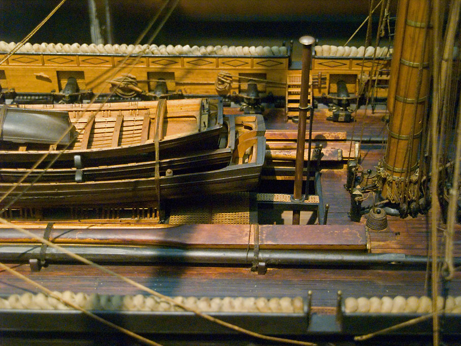
Actually, I have seen quite a number of models with hammocks in their boxes/netting and people discussing ways to make them, from rolled toilet-paper to epoxy putty ... The hammocks were tightly packed against each other - storage space was precious and not the whole crew's hammocks could normally be stored that way. Here is an image of a contemporary model of the French BELLE POULE (1834) in the Musée de la Marine in Paris, as fitted out to retrieve the remains of Napoleon I:
-
HMCSS Victoria 1855 by BANYAN - 1:72
wefalck replied to BANYAN's topic in - Build logs for subjects built 1851 - 1900
The 1847 edition is available on-line, the 1860 one not, as far as I know: https://archive.org/details/elementssailmak00kippgoog Didn't have time to check on the issue ...- 1,013 replies
-
- 4
-

-

-
- gun dispatch vessel
- victoria
- (and 2 more)
-
HMCSS Victoria 1855 by BANYAN - 1:72
wefalck replied to BANYAN's topic in - Build logs for subjects built 1851 - 1900
Pat, just a couple of comments on your questions in the last two posts: - you wouldn't need to worry about showing individual mast-wedges. They would normally be hidden under a painted/tarred sail-cloth cover that is nailed down to the deck and to the mast. The upper edge may also be fastened to the mast by winding a thin rope around it, that would also be painted over. - the eyelets/cringles for the mast hoops are usually set into the seams between two sail-cloths. Sometimes there is an additional in the middle of the cloth - this depends on the angle with with the cloths run against the mast and, hence, on the effective distance between the eyelets. The sail-cloths would normally run parallel to the after edge of the sail, so the angle at which the cloths intersect the mast depends on the angle of the after edge of the sail. - the hoops are normally strips of flexible wood that are thinned out at the end to overlap. The overlapping ends are 'sewn' together. At this point the hoops would be lashed to the eyelets/cringles of the sail.- 1,013 replies
-
- 3
-
-
- gun dispatch vessel
- victoria
- (and 2 more)
-
I don't know for the RN boats, but he German ones were originally painted black and later in the War in dark grey. I would assume that the decks assume after a short while a dark grey colour, similar to older tarmac, due to weather and wear.
-
Macro photos with an iPhone
wefalck replied to Tomculb's topic in Photographing your work. How to do this.
Yes, I have had such a slide since the early 1970s for my SLR (Novoflex, together with the bellows and all that gear), but getting the iPhone focus to stay at the place where you want it to is not so easy, as it tends to adjust itself all the time ... -
Macro photos with an iPhone
wefalck replied to Tomculb's topic in Photographing your work. How to do this.
One problem I have with close-ups and 'macros' using the iPhone is that it is very difficult to target the focal plane - there no really good manual focus. -
Cutting thin(!) copper sheet with a steel ruler and a cutter on a cutting-mat should not be really a problem. Don't try to cut through in one go, but in several passes. A pair of old(!) scissors should also work. Straighten out the strips/plates by rubbing them softly with a cork on the cutting-mat. You may also need to sand the edges slightly with very fine wet-and-dry paper to remove burrs. If you have a table-saw, you can also stick the copper sheet with a glue stick to some thin MDF or plywood and then cut the strips with a fine-toothed saw-blade.
-
New Workshop Bench Height ??
wefalck replied to PeteB's topic in Modeling tools and Workshop Equipment
I am virtually always seated when working, but then I have only miniature machines. When considering the height of benches for machines, one has to consider from which angle you would be mostly looking at the work, so that one can watch both, the surface worked on as well as the cutting tool (this being a lathe tool, saw blade, abrasive disc, etc.). When working seated on details, one may want to consider also arm-rests as e.g. jewellers use in order to relieve your back from bringing your hands up to eye-level for prolonged periods of time. -
Not sure, whether this was also correct for the RN, but in other navies at the beginning of the War, they ripped off deck-planking and Linoleum, particularly also on interior decks, in order to reduce fire hazards. This certainly did not improve the living conditions, but in war-time there are other priorities. Steel decks were typically painted in oil paint mixed with sand in order to improve the foothold during wet wheather. Or they used some wild concoctions containing cement, marine-glue etc. with coarse sand.
-
OK, this has all nothing to do with USS CAIRO in 1862 and we shouldn't dilute the building log with small talk ... at the end of the Cold War and after the Sovient Union disintegrated, Russia didn't need much of its Pacific and Northern nuclear fleets anymore and the submarines were laid up around Wladivostok and Murmansk. After some time, many of the surplus submarines were cut up and scrapped, keeping just the central reactor sections afloat. The reason was that Russia didn't have the necessary defuelling and decommissioning capacities and capabilities then. In the late 1990s the IAEA in Vienna organised a funding programme with international donors to ensure the proper defuelling and decommissioning of these reactor sections, as they were deteriorating and threatening to leak radioactive contamination from the primary reactor circuit. A colleague and friend of mine at the IAEA ran this programme in the 2000s. I myself have been involved with programmes to help the Russians sorting out the environmental contamination aspects of this.
-
Yep, you can knock out the brass inserts. They are a tight press fit with a dove-tail. I made some hardwood and Novotex inserts that simply could be hammered down (with caution), while in the case of brass or aluminium, you would need to file-/mill-on the rough dove-tail shape. If you don't get it completely right, you can probably also use Loctite or CA to fasten them, but I prefer it the old way. I made some flat jaws to work as a miniature hand-vice, but also milled recesses into the brass inserts to hold my bakelite micro-blocks while shaping and stropping them.
-
(Semi-)sunk Russian nuclear submarines in the North gave dozens of my colleagues for years a lot work
-
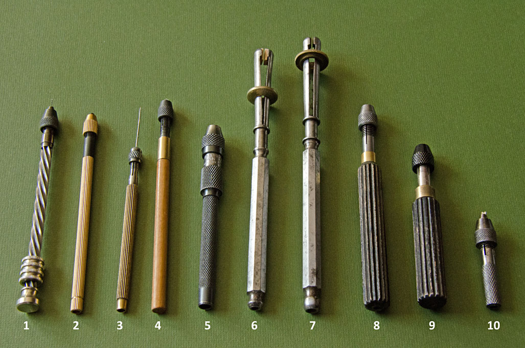
When it is about holding blocks during 'stropping' one can think about alternatives to hemostats. One can fiddle a wire loop through one of the bores and fix this wire somewhere on the workbench - this is akin to the full-size practice. For larger blocks, where the bores are big enough, one can also drive a headless steel-pin into a piece of wood and hold this in a vice or similar - the block then is hold by this pin while working on it. During manipulating blocks for shaping, people make themselves wooden clamps with a recess at the front to hold blanks. The principle for such clamps, albeit in metal, you can see at nos. 6 and 7 in the image below: It may also be possible to modify a wooden clothes peg for the purpose.
-
Macro photos with an iPhone
wefalck replied to Tomculb's topic in Photographing your work. How to do this.
I am quoting from memory, but the focal distance was less then 1", which makes it difficult to access details on a model and to illuminate the objects. -
Macro photos with an iPhone
wefalck replied to Tomculb's topic in Photographing your work. How to do this.
Yep, have one of those too. However, the 'macro' lens turned out to be too macro for our purposes. -
Macro photos with an iPhone
wefalck replied to Tomculb's topic in Photographing your work. How to do this.
Indeed, the 'magnification' is only done by software: when you save the photo you have just taken (not the screenshot), you get a normal-sized picture. When you 'zoom' the (i)phone just saves the cropped image, but the actual resolution stays the same. I do not bother with these fake zoom functions, but take a picture as close as the focal distance permits and then do all the cropping and post-processing in e.g. Adobe Photoshop. In order to avoid motion blur from your trembling hands, it is a good idea to get a Bluetooth remote control (as the come e.g. with 'selfie-sticks') - then you don't need to type on the phone. Some selfie-sticks also convert into table-top tripods, which reduce the blur even further. -
Good ! So, hopefully you will be back here in the not too distant future 🙂
-
Checked on 'hansard' yesterday, as confusing 'u' and 'n' is quite frequent, but none of my dictionaries knew this vernacular term from Normandy ... learned something
