


wefalck
-
Posts
6,664 -
Joined
-
Last visited
Content Type
Profiles
Forums
Gallery
Events
Everything posted by wefalck
-
 Didn't look into this thread for a while. It is coming on very nicely, the diorama. Love getting lost in detail ... The Jordan kits seem to have been available over here in the mid 1970s. I vaguely recall a review/building log in a German modelling magazine then. People were amazed by the detail in that scale. I remember envying other kids in the early 1960s, who had inflated tubes to go onto the water. My father never let me have one - perhaps because I wasn't able to swim yet at that time ... it was also difficult to carry the thing inside the car, when we were going down to the Rhine river on the summer weekends - it had to be inflated at a filling station.
- 189 replies
-
- 11
-

-

-
I think Håkan is right, the term 'tabernacle' also came to my mind. In other languages, e.g. German it is als called a 'mast-stool'. Otherwise I silently follow the evolution of this project. I find the choice of dark wood a bit sombre, but really like what you are doing with it !
- 153 replies
-
- 3
-
-
- Ancre
- Bruno Orsel
- (and 2 more)
-
Copper wire down to 0.05 mm is readily available from electronic supply stores or through the Internet. For small unstudded chains, such as used for hand-rails, I developed the following procedure: take two wires of the diameter that is appropriate for the scale wire diameter of your prototype; twist them together, so that the length of each twist is about the length of scale chain link; half the twisted wire and twist together the two halfs into the opposite direction with the same amount of twists - the result looks like a twisted chain. May need a bit of practice to get this done smooth and evenly. For galvanized chain - common from the late 1840s onward, I start with either blackened copper-wire and slightly dry-bush it in silver, or I take tinned copper-wire and let black ink/acrylic run into the depressions after twisting. For anchor-chains, of course, you need to check the protype dimensions and chose the right scale link sizes - there is no 'one-size-fits-all' or something like '1/700 scale anchor chain' ...
-
Nice subject. I had something like that in mind for some time, an early post-WWI type with a visible marinised surplus aero-engine - very detailed aero-engine kits have come onto the market for 1/48 WWI aircraft modellers.
-
Lancia Assunta by maurino
wefalck replied to maurino's topic in - Build logs for subjects built 1901 - Present Day
Where in the Adriatic does the prototype actually come from ? -
Brass piano hinges
wefalck replied to Chariots of Fire's topic in Metal Work, Soldering and Metal Fittings
'Chariot', have you tried ebay-shops (usually Chinese) selling hardware for jewellery-making and associated stuff ? The variety of items there you may have never seen or heard off before is quite amazing ... Otherwise, a DIY-process as Bob suggested may be the only solution ... check out the building logs of Michael Mott and KeithAug, if I remember correctly, at least one of them has done such small hinges. -
The tighter you wind the strands, the harder and stiffer they become - which means that the two pairs will slip past each other, with the final product looking like a three-stranded rope with a fourth strand running along a groove (diamond-shaped cross-section). Perhaps you rope was soft enough so that the strands squeezed together ... Making a ropewalk yourself and according to the dimensions you need is not really magic and certainly within the capabilities of anyone, who arrived at the stage, where he feels the need for proper rope ... the parts, such as gear wheels, bushings or ball-bearings, rods for axles etc. are readily available on the Internet; the other materials one can get at any DIY store. Unless one needs to produce hundreds of metres of rope, I find single-use machines, such as those of Domanoff rather expensive for the use they will get.
-
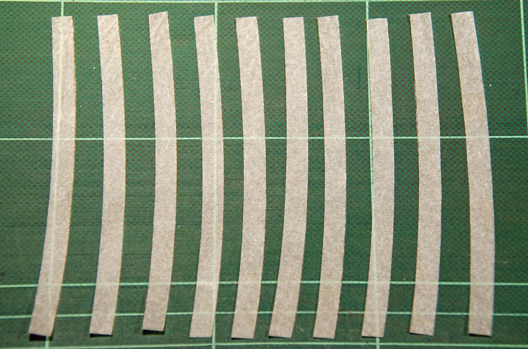
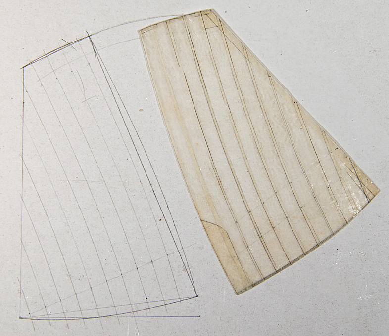
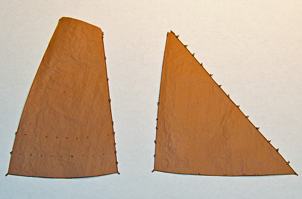
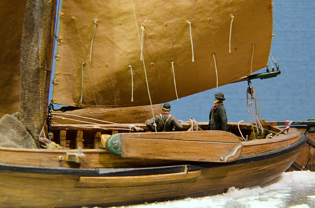
It is also quite possible to assemble silkspan-sails from individual panels and add doublings etc.: Cutting the panels from a sheet of silkspan stabilised with acrylic varnish Assembling the sail using acrylic varnish as glue Boltropes, cringles etc. attached as per Allen's description, sail also painted to look 'tanned' Sail rigged and reefing ropes attached It also works with what is called silkspan over here in Europe, that is a very thin silk cloth.
-
Thanks for the suggestions. It seems that the company is still around actually, at least for selling existing stock: https://www.irminiatures.com. However, looking at the pictures, the figurines are 1970s standard as far as details and animiation is concerned. In addition, individual imports from the USA have become largely a no-no due to high shipping and import duty costs, unfortunately.
-
HMCSS Victoria 1855 by BANYAN - 1:72
wefalck replied to BANYAN's topic in - Build logs for subjects built 1851 - 1900
I agree (from experience) that using some thread is easier to handle than wire for rigging. On the other hand, it depends also on the diameter of rigging and the metal chosen. Copper kinks relatively easily, but it easier to turn into loops etc. than harder wires, such as steel or NiCr. On the other hand, when twisted, the wire becomes less prone to kinking. There is also tinned copper-wire that is a bit stiffer than pure copper. I found it not so easy to turn more than two wires into an evenly twisted wire-rope. The tension on each strand has to be equal to prevent buckling of one or more strands. With some practice this problem perhaps could be overcome. The problem with using thread to simulate wire-rope is that the twist is much steeper than that of wire-rope and the individual strands stick out too much. When making your own rope, this could be perhaps overcome by trying to make a multi-strand rope from thin threads ...- 1,013 replies
-
- 4
-
-
- gun dispatch vessel
- victoria
- (and 2 more)
-
HMCSS Victoria 1855 by BANYAN - 1:72
wefalck replied to BANYAN's topic in - Build logs for subjects built 1851 - 1900
I agree with the others, she is coming along nicely ! Deck details, such as flag-locker really make a model coming to life. While the decks of a warship obviously were kept very well in order, they and the bulwarks were certainly not as empty as seen on some models. Metal or plastic sheet is a good choice for small detailed items such as the locker. Wood may be just to 'grainy' for that. Oh yes, and the bowsprit begins to look like the real thing too. I love this transition period, where 'engineering' slowly creeps into the traditional fitting out of ships.- 1,013 replies
-
- 4
-
-
- gun dispatch vessel
- victoria
- (and 2 more)
-
@knightyo, it appears that you picked copper-painted paper, rather than real copper-tape. Copper-tape today is available in various thicknesses and presumably with various adhesives. It seems to be used in various industrial applications as conducting tape. Another tradtional handicraft application is in stained-glass window and object fabrication, where each piece of glass is surrounded by copper-tape that is folded into an U-shaped channel; the pieces then are soft-soldered together. This tape is much thicker than that for industrial applications. I probably made this point earlier: coppering in seawater develops after a while a dull brownish-red oxidation surface. So the question is how you want to present your model, in working-day appearance or as a show-piece of your craftsman skills. In the latter case, I would not worry too much about the initial appearance of the copper, it will develop a dull reddish surface over the years, if not varnished. I don't know how at that time the sheet-copper was treated after rolling, but I could imagine that it was given a rub down with chalk after annealing between and after the rolling passes to remove scale. So, the plates probably would have had a clean uniformly copper-coloured satin surface. Therefore, I would not worry about giving the plates a different appearance. Any colour differences would even out after a while in the seawater. The effect of 'coppering' is probably based on a collection of processes, also depending on the species against which one wants to protect the ship. The copper plates are applied over a layer of tarred felt. Tar contains lots of unhealthy compounds, including polycyclic aromatic hydrocarbons (PAHs) and phenols, which probably would cut short the life of many nasty little things. The copper itself is smooth, making it difficult for barnackles and seaweeds to get a foothold. If they can get a foothold, say at the seams, they may dissolve some of copper - while copper is an essential element for many living things, too much of it is not very healthy. Then the copper surface is constantly, but slowly, eroded by forming copper-oxides and -sulfates, which again makes it difficult for unwanted growth to get a foot-hold. So overall, the copper-sheathing is a 'defence in depth', with various complimentary mechanisms.
-
I have used soldering tin with rosin core for this purpose. After pushing the drill through the jaws seem to close on it quite centrically …
-
I agree, that digressions into contextual aspects of the modelling subjects can be very interesting, as they help us to understand why things are as they are and how they were used ... The pieces of industrial history you mentioned are very interesting as such and over here in Europe we are certainly not aware of the details and interconnections. I could bend the story from IC powered tractors back to steam-powered farm implements by mentioning, that another big US American farm-machinery manufacturer, John Deere, bought out in 1956 a well-know German manufacturer, who started off with farm machinery in 1859 and then took up building portable steam-engines (locomobiles) in 1878 to become the biggest manufacturer in Europe. In the early 1920s they began to develop the IC powered tractor and the Lanz 'Bulldog' was successful well into the 1960s in its various variants, including road tractors that took over the role of steam traction-engines for heavy haulage.
-
What paint brushes to get?
wefalck replied to Ed Gibbons's topic in Modeling tools and Workshop Equipment
Recommending brands is always tricky as their availability depends on the continent you are on. Nevertheless, I have been using DaVinci synthetic brushes for decades. As noted by a colleague, they come in many diffrent shapes and sizes, intended for different sorts of jobs. These diffrent shapes are mainly designed for use on flat surfaces. I personally found that on models with their three-dimensional surfaces the standard brushes with long hairs often do not work so well, but there are also types with shorter, stiffer hairs, e.g. so-called spotters, that work better. There are also speciality brushes, such as lining-brushes with very long hairs, that are traditionally used by sign- or coach-painters to paint long, narrow lines. In more recent years they also seem to be used by so-called nail 'artists'. They are difficult to use on small, three-dimensional surfaces, unless you have a lot of practice (which I don't). Having said that, I prefer to spray-paint using an air-brush whenever possible and when a uniform coat of paint is required. -
As far as I am aware, there are two (traditional) types of lug-sails, the standing lug and the dipping lug. As the name indicates, only the dipping lug is normally shifted to the lee, when tacking. The difference is that the part of the yard before the mast of a dipping lug is shorter than that of a standing lug. Also the tack of dipping lug is belayed onto the mast, so that in consequence the luff is inclined. On a standing lug the tack is belayed somewhere forward on the boat, so that the luff is more or less vertical. A standing lug can also be taken around the mast, but you will need more crew for this to control the tack and the large part of the sail before the mast. You probably have to take the sail down for this except in very light winds. Tradtionally, lug-sails do not have a boom - for a good reason, because they are the sails of working boats, where you want to take in the sail quickly with a small crew and do not want to clutter the boat with another spar where you have to handle nets etc. The boom seems to be a modern addition to sporting boats.
-
" ... But I digress, sorry.... " Yes, the original post was about steam-ploughing machinery
-
What they do in museums for cut-away models is to paint the cut cross-section of metals (oxide) red and that of wood is left in its natural colour. This would also nicely off-set the iron cladding against the wooden backing of the armour.
-
If it is 'stainless' it would be virtually impossible to solder - soldering relies on forming a sort of alloy between the solder and the material being soldered. Stainless steel can be welded, but this requires normally a protective atmosphere (e.g. a flow of argon gas). Electric spot welding would also be possible. If one has a lathe, the best way would be replace the part with a turned one probably. Or I would have turned a wooden core to match. Looking forward to further progress in the construction ! Love those 'mechanical' projects.
-
I am not wheelwright, so I don't know anything about their reasoning. However, in reality it may not be sufficient to look at the static aspect, but also at the dynamics. Depending on the surface over which you move, the load will not only have a vertical force, but there may be other components, in all directions relative to the movement. In some cases, also the camber of the road is taken into consideration - having a curved axle adds springiness. The reasoning of using would without defects makes a lot of sense, but I think it could probably also applied to wood, where the grain follows the curve of the piece (or rather the other way around.
-
Inclined or curved spokes give the wheel are certain springiness, thus protecting the wheel itself against bumps, as the well as the load. I don't this is meant to be ship-board carriage, rather to be a gun to be used in a fortification. Probably something to be used in landing operations, where temporary field fortifications would be errected. The recoil on a low carriage with small wheels would be easier to control, than on a field piece with large wheel. Not sure since when braking shoes on field have been used. For carriages and waggons they were used at least since the early 1600s I think.
-
Keith, I would agree with Pat, that the placement of the windlass-barrel half-way above the hatch is awkward - for the use of both, the hatch and the windlass. There is another mechanical/operational issue with this being a windlass: one has to somehow stop the backslash. On very primitive windlasses this is done by having the holes of the handles off-set by 90° at both side of the barrel. While heaving on one side, one inserts another handle at the opposite side, so that maximum backslash would be 45°. Not very safe to operate and, therefore, at least since the 18th century pawl-drums were used, i.e. a sort of broad ratchet-wheel with saw-teeth. Into these teeth fall the pawls that are mounted on a pall-bitt in the middle of the windlass and in front of it. This pawl-bit is missing in the present arrangement. When I first saw the picture, it made me rather think of a cargo-winch. Such cargo winches had two spill-heads on each side. They were normally geared, which means that there was an axle above the winch stem that carried hand-cranks on both side. Power was transmitted through a pinion and the gear-wheel. At one of the bits there would be also a ratchet-wheel and a pawl.
-
boom rigging on a ship's launch boat
wefalck replied to Peanut6's topic in Masting, rigging and sails
Permit me to disagree, Roger. I rarely saw belaying pins on boats and this for a good reason: they are easy to loose and cleats would be probably stronger too. Cleat are also safer, particularyl when arranged horizontally inside the hull or parallel to spars, such as mast or booms (which also is needed because of the direction of pull, of course. I wouldn't like to step onto a belaying pin sticking up vertically inside a boat ... -
Ah, that's why it looked familiar. I have no special interest in London buses, other than that I am rather emotionally attached to London (including the old open-platform 'Routemaster' buses) since my first vist in 1972 and later having lived and worked nearby for some time. I certainly would have made a lot of the mechanics from PE, rather than cast them in resin. There would be lots of opportunities to make a much more detailed kit. If I am not mistaken, Airfix at some stage also offered a kit of a London bus as converted fro military service in Flandres during WW1. Or may be this was a conversion in old modelling book from the early 1970s I have. There was a shortage of military motor vehicles, so the Brits and French (the famous Parisian taxis) pressed civilian vehicles into service. I gather there are not too many kits of early buses. Berlin also had motor-buses very early on.
-
Sorry, but what girl are you talking about ?

