


wefalck
-
Posts
6,644 -
Joined
-
Last visited
Content Type
Profiles
Forums
Gallery
Events
Everything posted by wefalck
-
 Actually, the 'tarred' bilge looks very convincing ... the rest is coming on nicely too.
 -
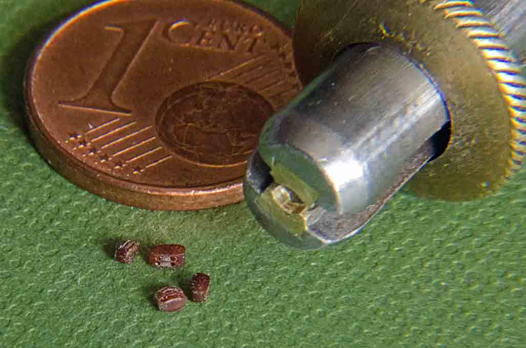
I litterally spent the last six months trying to solve exactly this problem. For my current project I need only 1.6 mm and 2.0 mm long double outside iron-strapped blocks in a shape appropriate for the later 19th century, but I meant to develop a procedure with which I can make larger number of reasonably uniform blocks down to 1 mm length. There were originally two main criteria: a) avoid drilling numerous tiny holes down to 0.1 mm diameter and b) ensure that the rope runs out tangentially from the block and doesn't stick out radially with a sharp kink. Many years ago it occurred to me that one could etch the shells and sheaves from brass sheet (using surface etching) as parts that can be folded up and then soldered together. Unfortunately, at the moment I am not set up for etching anymore, so this idea was not practical. Since I bought a small laser-cutter about two and a half years ago, I attemped to adapt the above idea and cut the pieces from Canson-paper. Cutting the parts as such went well, but the precise alignment of the tiny flecks of paper proved impossible and the holes for the rope tended to fill up with the lacquer I used for laminating. Being paper (albeit soaked in lacquer) the blocks could not really be sanded - particularly holding them for the purpose was just not feasible. After numerous attempts with different configurations for building the blocks from layers I gave up. I also attempted a variant of the above using brass sheaves and making only the shell from paper. However, turning 0.6 mm brass sheaves of 0.2 mm or less thickness did not work even on my watchmakers lathe, at least not in quantities. I tried the method of building up layers from styrene sheet and using brass sheaves. While styrene sands better than paper, the problems of holding and making the sheaves remain. For an earlier model I had tried to mill and drill blocks from brass or perspex rod. Perspex is easy to machine, but thin parts are very brittle. Brass can be machined to intricate shapes, but drilling multiple 0.2 mm holes into brass is a challenge and may result in many broken drills ... In the end I reverted back to a miniaturisation of the traditional method of shaping blocks in a row from strips sawn to the outside dimension. However, I am not using wood, because the grain, even in boxwood, causes problems at these small dimensions. I prefer to use brown bakelite as used in electronics and electrical applications. Bakelite can be a bit brittle, but machines and polishes well. The procedure I finally arrived at is (based on the capacity of my micro-milling vice, I working with batches of eight blocks) for a 1.5 mm block: 1- Cut strips that are a tad wider than the blocks are long from bakelite sheet of suitable thickness (here 1 mm) 2 - Mount strips into the milling vice so that 0.15 mm deep grooves for the sheaves can cut with a 0.2 mm circular saw blade 3- Repeat from the other side 4- Re-orient the milling vice so that at one end, in suitable distance from the edge, 0.2 mm holes can be drilled through the grooves 5- Re-position the strip, so that the grooves for the strap can be milled into the top- and bottom-ends with a conical burr 6- Rough-shape the block by milling off the corners with the same conical burr 7- Take the strip back to the circular saw and cut off the individual blocks 8- Hold the block in a pin-vice that has a recession milled in and round-off with a rubberised abrasive wheel in the hand-held drill 9- Round-off the groove into the drill-hole using a tiny graver fashioned from a piece of 0.2 mm thick piercing saw blade (for holes above 0.25 mm diameter also diamond-studded piercing saws wires are available that can be used for this) The blocks are now ready for the external strap. I tried the strapping with flattened copper-wire, but this proofed to be too flimsy and broke all the time. In the end I used the round wire, although this is not quite correct - there are limitations. Basically, I loope the wire around the block and then drilled the two ends together. For blocks that have an eye at one end, the eye was first formed with very fine tweezers and the wire then looped around the block as before. The block was held in the same adapted pin-vice as above. A collection of blocks and the special pin-vice to hold them This is how far I got. The next step will be forming the hooks and stiffening them with solder. Otherwise the wire is too soft. Earlier stages of these tries are illustrated in my current building log:
-
Very clean work, as usual. Are these doors stamped or soldered together from two layers ?
-
No. The yoke was used when rowing and under sail. Locking the rudder would make it rather hard to steer the boat with the oars and it is very tiring for the rowers, when they constantly have to adjust the speed or force to make small corrections of the course. This is done by one or two 'helmsmen' at the rudder pendants according to the commands by the NCO or officer in charge of the boat.
- 433 replies
-
- 5
-

-

-
- open boat
- small boat
- (and 1 more)
-
On the yoke vs. tiller: I had a look in my old textbooks on naval boats, but there they state that cutters may use a yoke for steering and it is not very wide. I gather, when being rowed, sharper turns can be achieved by rowing on one side only, while under sail, the driver placed far aft, yawl-fashion would aid the steering by either hauling it more or less taught, so changing the tendency of the boat going into the wind or otherwise. Thus the rudder would only be needed for small corrections of the course.
- 433 replies
-
- 3
-
-
- open boat
- small boat
- (and 1 more)
-
Nice work on the flags. And I agree that printing on thin paper is probably more successful. I usually then repaint with acrylics, as the the printer inks may not be very lightfast. Also liked the 'engineering' approach to the grapnels. Not so simple to recreate these simple fire-welded units. The flags made me curious, as they have as the main motive the colours of Aragon (the red and yellow stripes), which also appears in the flags and coats-of-arms of Catalonia, Barcelona, Valencia, Spain in general, and various others. Its a long story dating back to the Counts/Kings of Aragon, who sort of spread to the coastal zone of Eastern Spain and SE France as the Reconquista progressed. A bit of the history and the flags can be read here in German/English: https://www.flaggenlexikon.de/ffrkprov_dt.htm. It appears that your flag was created only in 1999 for the then newly created 'region' of Provençe-Cote-d'Azur (the French administration assembled a number of the Départements created after the French Revolution into larger units of certain economic and cultural coherence over the past 20 years or so, to some degree re-establishing the ancient feudal-political units that the revolution intended to break up).
-
To my knowledge Lees reviewed the literature and the models of the time. With models of the time it is always an uncertainty, if and when they might have been re-rigged or 'restored', of course. However, these are the best guesses we have. Books that cover a too wide range in time and geography are always problematic, because they will lack in depth and thoroughness - due to the limited knowledge of the authors and constraints imposed by the publishers (who are only interested in what sells, not what might be useful for a small group of afficionados).
-
The question may be a bit too late, but weren't the oars not to have a metal band around the blade to prevent splitting ?
- 433 replies
-
- 4
-
-
- open boat
- small boat
- (and 1 more)
-
According to my 1878 textbook on naval (and other boats), the cutters in the Imperial German Navy, which were modelled after those of the RN according to a statement in this book, had a yawl-rig with lug-sails and a short running bow-sprit, very similar to the drawing David showed earlier. The driver-mast was bracketed to the transom. Gigs and smaller boats had a single lug-sail. I have no information on Italian naval boats, but it seems that they were quite similar all around the world at that time.
- 433 replies
-
- 5
-
-
- open boat
- small boat
- (and 1 more)
-
Well, this are not so good and good news: you might get faster to a solution of this problem. Good luck and take it easy afterwards !
-
That breath of fresh air might be needed Although, the sailors of old usually had lots of that, when going over that business. Smaller boats, such as fishing boats had no facilities of any kind, one had to hang the bottom over the rails ...
-
To be hones, I never understood the concept of 'first model'. If I knew about a problem and about the possible solutions, I would have the ambition to correct it. Otherwise, I would see this every time I look at the model later and would regret ...
-
They still seem to have been in use in lower end housing between the wars in Germany … they were called ‚gold buckets‘ …
-
It is quite possible that buckets were used and that the seat of ease contained a bucket, rather than opening to the outside. Sometimes small vessels had in later years small deckhouses at the forward bulwark one both sides (one may have been the paint-locker) with a half round roof. That's for 'serious' business, otherwise you just pee over the lee-rails or into the gutter ...
-
I was about to make the same comment as 'Beef Wellington', the barrels are way to small for the carriages or vice versa. In order to determine which one might be right for your ship (what is 'LN' ?), you could have a look what kind of guns she would have carried and then check against contemporary sources how big the guns would have been. Another possibility to check is to measure the hight of the bearings for the trunnions above the deck - this should be more or less at the middle of the gun ports so that the muzzle would be in the middle of the gun port (as was pointed out by someone already), when the barrel is elevated to the horizontal. Hopefully, one of them is the correct size. Then it would be a good idea to make either the barrels or the carriage from scratch. There are lots of ideas how to do this on this forum.
-
Imitating expensive woods (or marble) has been very much en vogue until the 1920s or and still seems to enjoy a certain tradition in some countries. Some 30 years ago I picked up this instruction manual: Hemming, C. (1985): Paint Finishes.- 144 p., London (Macdonald & Co.). that describes in detail how to do 'wood-graining', 'marbelling' and other techniques and what tools and materials to use.
- 433 replies
-
- 5
-
-
-
- open boat
- small boat
- (and 1 more)
-
How many did you need to make to get ten right ?... I don't want to be nasty, but just have a bit of consolation that others are also struggling with small and flimsy parts
- 433 replies
-
- 4
-

-
-
- open boat
- small boat
- (and 1 more)
-
You are absolutely right, there is no modern book that summarises the developments from the middle of the 19th century to its end, particularly for naval vessels and those of mixed propulsion (Underhill and others cover most relevant aspects for the merchant navy sailing vessels). Some kind of continuation of Lee's book, but one needs to look at the various countries as well, as many innovations happend also e.g. in France. ... Perhaps a retirement project for me
-
Sherline Mill Essential Accessories?
wefalck replied to Some Idea's topic in Modeling tools and Workshop Equipment
That's a nice Renishaw tilting table that you have there ... their stuff is interesting, but rather pricey. Looked at it years ago and took some inspiration for home-made equipment. That's the beauty, when you have a lathe and a mill that take both the same spindle tooling, you can make a lot of tools for them yourself. -
Sherline Mill Essential Accessories?
wefalck replied to Some Idea's topic in Modeling tools and Workshop Equipment
Well, ER are chucks are compressed from the conical surface, when the nut pushes it backwards into the cone. Due to the slotting from the front and the back, they have a rather wide clamping range, typically 0.5 mm per size. For this reason they are sold in 0.5 mm steps. ER collets below 1 mm nominal diameter are difficult to manufacture at an acceptable quality/price ratio. You can make yourself a sketch of the resulting forces and of what happens, when you insert a short workpiece into such a collet: there is a tendency to bend the collet tighter at the end, where it is not held open by the workpiece, as you push the collet in with the nut. This has a forward resulting component of the forces, that is the stronger, the shorter the workpiece is. Of course, if the tool goes through the full length of the collet, the bore of the collet will lay down equally onto the whole length of the tool. This is why ER are superior to the other collets, when it comes to tool-holding, because of the large contact surface. This distortion with short workpieces cannot happen in other types of collets that are only slotted from the front. The solid ring at the end prevents such distortion. They have a much narrower clamping range, usually 0.2 mm, and therefore are typically sold in 0.2 mm steps (at least for the size range of machines we use in our workshops). If you clamp a workpiece or tool the diameter of which is less than nominal diameter minus 0.2 mm, than it will indeed pinch only with the front edge, resulting in damage to both, collet and workpiece. Normally the bearing surface in such collets is between 0.5 and perhaps 2 or 3 mm long, so that even very short workpieces can be held securely. In my watchmakers lathe collets I can hold securily discs of 0.5 mm thickness and several mm in diameter. Such collets are manufactured normally from 0.2 mm nominal diameter upwards. One should also add, that into neither type of collets tools or workpieces larger than the nominal diameter should be forced. This will distort and eventually destroy the collet. -
The problem is that the period in question has seen a dramatic evolution in rigging technology and practice. While things in principle became simpler, they have become more difficult to reproduce in (smaller) scale. For the standing rigging iron and then steel began to replace plant fibres as iron armatures began to replace good old rope stroppings on blocks and shackles replaced hooks or knots. Also in many places chains were used. This affected in particular also steam vessels, whose rigging and sail plans more and more deviated from the classical categories and layouts. In consequence, I don't think PETERSSON, L. (2000): Rigging Period Ship Models. A Step-By-Step Guide to the Intricacies of the Square-Rig.- 128 p., Washington (US Naval Institute Press). is going to be very helpful. I believe he focuses on the 18th and early 19th century. Better sources that show more modern practices would be: BIDDLECOMBE, G. (1848): The Art of Rigging.- 155 p., Salem, Ma. (Reprint 1990 by Dover Publication, New York). BRADY, W.W. (1852): The Kedge Anchor; or Young Sailor’s Assistant. Appertaining to the Practical Evolutions of Modern Seamanship, Rigging, Knotting, Splicing, Blocks, Purchases, Running-Rigging, and Other Miscellaneus Matters Applicable to Ships of War and Others.- 400 p., New York (Published by the Author). BUSHELL, C. (various edtions from 1856 to 1893): The Rigger's Guide and Seaman’s Assistant Containing Practical Instructions for Completely Rigging Ships of War – Second Edition, with sixteen addtional pages on wire rigging.- 214 p., London (H. Lewis). FINCHAM, J. (1854): A Treatise on Masting Ships & Mast Making.- 384 p., London. KIPPING, R. (various edtions between 1853 and 1903): Rudimentary Treatise on Masting, Mast-Making, and Rigging of Ships.- 150 p., London (John Weale). UNDERHILL, H.A. (1946): Masting & Rigging the Clipper Ship & Ocean Carrier.- 304 p., Glasgow (Brown, Son & Ferguson). If I was allowed only one book, I would go for Underhill. Biddlecombe and Brady give more practical details, while the later works are more concerned with the layout of riggings. I am not aware of an English-language book that specifically covers the period 1870/1880 and naval ships, while there is for instance a very good one in German for the austro-hungarian Navy. A good book with lots of very illustrative drawings relevant for the early part of the period is also BOWCOCK, A. (2002): CSS Alabama. Anatomy of a Confederate Raider.- 191 p., Rochester, Kent (Chatham Publishing).
-
YOUNG AMERICA 1853 by Bitao - FINISHED - 1:72
wefalck replied to Bitao's topic in - Build logs for subjects built 1851 - 1900
Coming along nicely - what else ? .... I forgot what your plans were, will she be rigged ?- 257 replies
-
- 2
-
-
- young america
- Finished
- (and 1 more)
-
3d printing crew figures
wefalck replied to highlanderburial's topic in 3D-Printing and Laser-Cutting.
Daniel has become already pretty good with UV-curing resin printer and I have been bugging him to re. printed blocks, but the main problem is not the printing as such, but producing the digital sculptures (as someone last autumn already noted). It is a long way from turning your manually sculpted figures into printable files. Someone has to do that. As far as I know, Daniel is not really into 3D figure sculpting. Such things are always commercial questions, but it would be interesting to have a system similar to the abovementioned 'Hero Forge', where the basic animated figurines can be kitted out for different periods. There would be a range of basic poses that do not really change from century to century, but the attire will change more or less, say a group of sailors pulling at a halliard, going up the mast, furling sails, holystoning, etc. etc. If done in sufficient detail to cover say the 54 mm (=1/32) scale, they then could be printed in any smaller scale. -
If you want to see the botters in action, here is a film made in 1930, shortly before all that disappeared because the Zuidersee was dammed-up: