wefalck
-
Posts
6,642 -
Joined
-
Last visited
Content Type
Profiles
Forums
Gallery
Events
Everything posted by wefalck
-
However, I would be rather hesitant to use any such chemicals on plates that are already on the model. It is impossible to prevent the solutions from creeping between the plates and there they may create havoc with the cement ... otherwise yes, oxalic acid is a good complexant for divalent ions, such as Cu(II), and will bring bring any CuSO4 into solution. I gather you meant to use the descaler 'CLR' as an alternative to oxalic acid not alternating between the one and the other ?
-

Poly over acrylic paint????
wefalck replied to CPDDET's topic in Painting, finishing and weathering products and techniques
I would always be very hesitant to mix two paint systems. You may be lucky, but it can also spell desaster, depending on what the products actually are made of. Why would you want to put varnish over a painted surface. I would carefully reflect on the reason. Perhaps, acrylic paint isn't the right paint for the job, if you think you need to further protect it. Perhaps you should use a different paint system - there are also many different acrylics-based paint systems. Depending on the type of model, I personally also like the different sheens of different paints for different parts. A real ship would not be all over glossy or matt or satin. -
I knew most of the drawing instruments presented above and have several sets, one was given to me, when I started in secondary school and it is still in mint condition, the others I inherited. However, I never came across the Barch-Payzant lettering pens, they must be an US American speciality. In Germany we used for this what would be translated as 'funnel pens'. They are indeed tiny funnels that can be attached to a penholder in a way to keep the pipe of the funnel vertical on the paper. They were made in standard diameters to fit lettering templates. A thin wire ran through the pipe to keep it from clogging. They were essentially the forerunners of the technical drawing pens with an enclosed ink-reservoir or cartridges.
-
OK, it's sure choice, but I wouldn't want to have bright plating .... having said that, if your copper turns green, you have a serious corrossion problem somewhere. Green means copper sulfate or copper acetate, usually. You may have not done yourself (or rather the model) a good service by using vinegar (acetic acid) on the copper. If the green appeared before you applied the vinegar, you should investigate, where the sulfur/sulfate may be coming from before doing anything else. Or perhaps you cleaned the copper with vinegar before applying the plates and did not neutralise and rinse it properly ? Normally, copper in a household atmosphere just becomes a dull copper-brown. At the seaside or in heavily polluted industrial areas this may be different, but Colorado is neither, I believe.
-
Gary, chromatography 'columns' are always stainless steel. Albion Alloys in the UK sell brass tubes from 0.3 mm OD up with a wall thickness of 0.05 mm. In fact they sell tubes that are slide-fits into each other, so the next sizes up would be 0.4 mm OD with a wall thickness of 0.05 mm and so on. They are quite expensive though. Not sure what they are normally used for, as I don't think they are made just for modellers. Hypdodermic needles are also stainless steel tubes essentially. The thinnest ones are those used for insulin syringes. Not sure about the size, but they could be below 0.3 mm OD. The raw material for the syringe manufacturers presumably are coils of such drawn tubes, but I don't know, whether one can come by this material as normal mortal.
-
Thank you to you both for your kind words. Unfortunately, the path is not so straight. Which is, in addition to frequent interruptions due to business travels, a reason for the long intervals between postings ...
-
I had the same thought about grounding, but these tubes would be difficult to solder - they are used as chromatograpy ‚columns‘ and therefore must by of highly corrosion-resistant stainless steel. There are on the market also brass tubes of a similar diameter, I believe.
-
nubie question regarding string and knots
wefalck replied to EricWilliamMarshall's topic in Masting, rigging and sails
Knots are actually a bit of intuitive engineering, meaning that people over the millennia realised what knot with what material gave the best holding power, while still being able to be loosened (which is a key property in marine knots!) if and when required. Originally, these knots where developed for twisted/laid rope. There, the holding power derives from two properties: the locking of the strands of the rope and the friction between the different parts of the ropes. For this reason, some traditional knots do not hold very well with modern braided ropes. For the same reason, these knots may not hold very well with straight or only slightly twisted threads. The surgeons use catgut or similar, more modern materials, which is only slightly twisted and quite smooth. Hence the overhand knot does not hold very well and the surgeons added more twists to it. The modeller faces a similar problem, when simple threads instead of a properly laid model-rope is used. One day, you may move to making your own laid rope or buy some ready made and you will see that the mariner's knots will hold much better with this material. -
Didn't follow this thread so far, as it is not really 'my' period. However, looks like an interesting approach with the shop laser-cut parts. Just got myself a little toy laser-cutter to play around with ...
-
Instinctively, I would have glued the brass sheet to the wood, say using some CA or even a glue stick, but taking them up together sounds like a good idea.
-
Switched from X-Acto to Excel blades......
wefalck replied to CPDDET's topic in Modeling tools and Workshop Equipment
Most 'hobby'-shops tend to sell things in small quantities at elevated prices to innocent/ignorant modellers. Very few tools are specifically made for us, but rather are adapted from other trades, includings medicine, jewellers, horologists, dentists, etc. It pays to check out the tools of profession that work on small and delicate things. Whatever you may think about ebay, it has opened up the market for all sorts of things that would be otherwise difficult to come by or might get thrown into the (recycle) bin. I got a life-time supply of scalpel blades in all sorts of shapes at a very good price from an ebay-dealer, who sold sterilised scalpels in packs of 100 that where beyond the 'best before date', i.e. the date up to which the manufacturer guaranteed the sterile condition. Presumably a medical supplier or a hospital had thrown them out. -
nubie question regarding string and knots
wefalck replied to EricWilliamMarshall's topic in Masting, rigging and sails
These are the same as the 'real' ones. I usually get away with the half-hitch, double-half-hitch, clove-hitch, reef-knot and perhaps the sheet-bend. There are lot of Internet-resources on how to tie these knots, including animations (if you a geometrically challenged). As to the shellac, which usually has a slightly orange tint, you have to try it out on the material you want to use. The more it is diluted the less the colour becomes visible, but also its sticking capability reduces. Like so many things in modelling, you just have to try and find out what works best for you and the materials you are using. -
Brush painting hull ??
wefalck replied to CPDDET's topic in Painting, finishing and weathering products and techniques
Personally, I am not very fond of brush-painting acrylics for a couple of reasons: - one has to work very fast, as acrylics dry very fast, in order to avoid brush-streaks - acrylics remain slightly rubbery for a very long time, days, if not weeks; until they are not thoroughly hardened, it is difficult to sand them - one would need to paint the surface in one go, as quickly as possible and without interruptions, i.e. wet in wet. I am not an expert in high-quality brush-painting, but one of the techniques/strategies is to rub run down the layers of paint and then to repolish the last one to the shine desired. This is very difficult to do with acrylics for the said reasons. The brush size really depends on the size of the surface you want to paint. So, today, as air-brush equipment will cost you probably less than a meal for two in a good restaurant (depends on where you are living, of course), there is hardly a reason not to use spray-painting. And for this, acrylics are ideal. -
Do a bit of searching on the Forum, the various techniques and options for materials have been discussed before here. Just to make it clear, there is/used to be finely woven silk (silkspan in the USA, but this may be product name) and silk-paper for covering model aircraft wings and other parts. Both materials can make useful sails and have their pros and cons. It depends inter alia on the scale one is working in. A substitute for 'silkspan' may be also the fabric that is used for screen-printing, but I have no practical experience with it. It seems to be easier to get than 'silkspan' these days.
-
Over the weekend I have been to London and as our hotel was around the corner, my wife suggested that we visit once more the Wallace-Collection. Sir Richard Wallace and his father have put together also a nice collection of Dutch paintings, including a good number of seascapes. For a colleague over in the forum of the 'Arbeitskreis' I took pictures of several hoeker-like vessels (https://forum.arbeitskreis-historischer-schiffbau.de/viewtopic.php?f=16&t=1874) and also what I think may be an early form of a 'boeier'. In any case, judging by the carved and gilded decorations, it is obviously a pleasure-craft: J. van der Heyden (1637-1712): View of the Westerkerk, Amsterdam. Perhaps Ab can correctly identify this vessel ?
-
druxey, you are right in principle and I also have been an advocate of 'permanent' materials. On the other hand, I have a roll of gummed packaging tape that by now may be a hundred years old, considering the way it came into my possession, and it is still good as new. Perhaps over a 500 year time-scale things may be different ...
-
I only recently learned, when visiting the London Canal Museum last weekend, what Esparto Grass was used for: paper-making. It is mainly grown in SE Spain, in the provinces Valencia, Alicante, Murcia, and Almeria. The Spanish name is atocha. Perhaps, this is why Madrid's main station for trains to the South is called Atocha, leading to the plains, where Esparto Grass grows.
-
nubie question regarding string and knots
wefalck replied to EricWilliamMarshall's topic in Masting, rigging and sails
Perhaps I wouldn't use the word 'coating' and the underlying concept. The idea is to soak the rope material in order to stiffen it. When soaked-in, the lacquer/varnish becomes invisble, a 'coating' by definition is a visible layer. -
nubie question regarding string and knots
wefalck replied to EricWilliamMarshall's topic in Masting, rigging and sails
Nail polish is essentially the same as zapon lacquer, except that is comes in smaller bottles and, hence, is more expensive ... Beware, some nail polishes are acrylic-based and do not dissolve readily. -
This topic seems to pop up over and over again. A search through the various building logs might be useful ... As druxey said, the 'dimples' are barely visible on the real ship from a view metres away. They are, however, one of those details that, when left off, may make the coppering look rather sterile. On the real thing you can see that there is something, but you can't really tell what it is, when you are some distance away. What you can do depends very much on the scale you are working in. In scales of 1:48 or above, I would perhaps imprint lightly the nailing into the copper sheet using a copying wheel (sewing supplies) and then flatten them again from the back with a round piece of hard wood. This gives you quite realistic 'dimples' that are not proud of the surface. There are very thin copper adhesive strips where you may use the same technique for even smaller scales. I have used them for rivetted plates, but not for copper sheathing yet using the above technique. Always use a glue that sets by evaporating the solvent, i.e. contact cement, and not something that polymerises, i.e. CA cement. Copper ions can inhibit the polymerisation. Also CA can react with the oxide film on copper, leaving bright spots, and it is difficult to remove excess cement. Excess contact cement can usually be wiped off with a solvent.
-
nubie question regarding string and knots
wefalck replied to EricWilliamMarshall's topic in Masting, rigging and sails
I should have added that the varnish I use is the kind of thin cellulose varnish that is used to protect silver and brass ware from tarnishing. In continental Europe we call it zapon lacquer and it dries alsmost invisible. -
Bench Top 5" Disk Sander
wefalck replied to DocBlake's topic in Modeling tools and Workshop Equipment
Any equipment that constitutes an Ohm-resistor (collector motors, soldering irons, incandescant bulbs, etc.) can be controlled with a simple dimmer - but check that it is rated appropriately. Dimmers are either available for wall mounting (which can also be set into a workbench) or as 'plugs' to go between the plug of your equipment and the wall socket (hence, no installation is required). I have a dimmer hooked up to a foot switch from which I run all machines. This has the advantage that they are only under power when needed and that you can interrupt them by simply lifting your foot. The rpms are preset, so you can return to the same setting by pushing your foot down. -
nubie question regarding string and knots
wefalck replied to EricWilliamMarshall's topic in Masting, rigging and sails
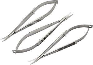
The tool of choice would depend on the location and its accessibility. I typically use the following: - micro-scissors for eye-surgerey (Castrovejo-style); they can be very expensive, but I got mine as 'seconds', which are good enough for our purposes - check ebay et al., where one can find all sorts of medical instruments these days; the most useful is the curved type, as it lets you get close to the point of cutting. (Found even on Amazon ...) - ordinary scalpels with replaceable blades - broken-off pieces of razor-blades - there a special holders for these, but they are ridiculously expensive; you can hold it in a pin-vise with a double-slotted head/collet; razor blades probably give the cleanest cuts after scissors. - antique biological lancets for tight spaces; they have to be honed on an arkansas stone to have a really keen edge. Don't use your scissors and lancets for anything else but rigging work. I soak all splices and knots in clear varnish, rather than PVA or CA glue, as I can loosen them with solvent, should the need arise. Incidentally, you will find that splices are much more common than knots. The latter are mainly used to belay ropes, rather than attaching them to say blocks. You can fake splices by drawing the end twice through itself using a needle, cutting off the excess and then roll the splice between your fingers with a bit of varnish on.