


wefalck
-
Posts
6,652 -
Joined
-
Last visited
Content Type
Profiles
Forums
Gallery
Events
Everything posted by wefalck
-
 I love making such mechanical things. Here my take in 1:60 scale, done some 30 years ago:
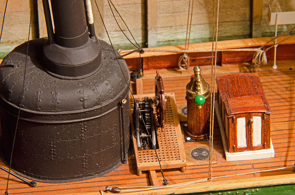
-
... you could use black decal strips, either home-made from decal sheet or commercial ones. I am also using increasingly soft artists' felt-tip pens with pigmented acrylic paint in them for such things.
- 732 replies
-
- 4
-

-

-
- Lula
- sternwheeler
- (and 1 more)
-
So it kind of operates like the knee-levers on electrical sewing machines? Interesting mechanism. She now really looks like a hard-working vessel 👍🏻 I like these unsual workboats.
- 732 replies
-
- 5
-
-
-
- Lula
- sternwheeler
- (and 1 more)
-
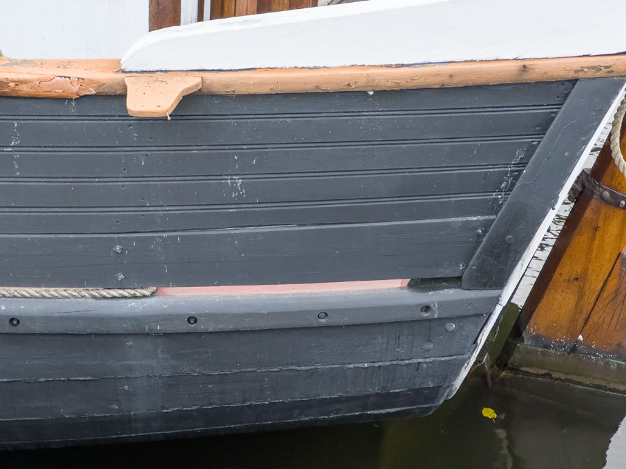
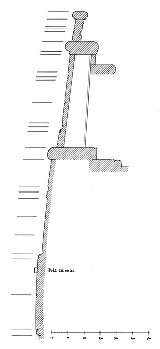
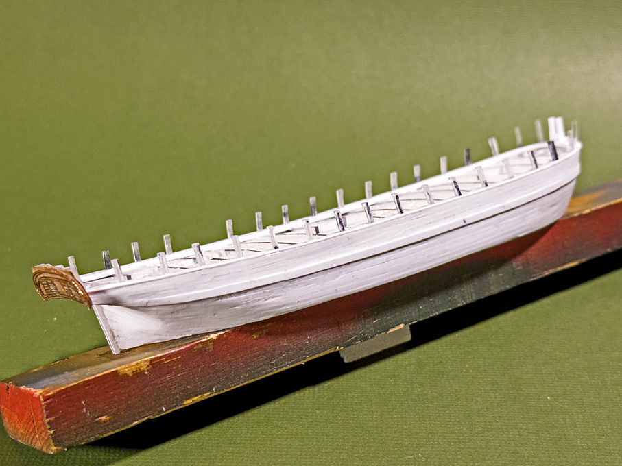
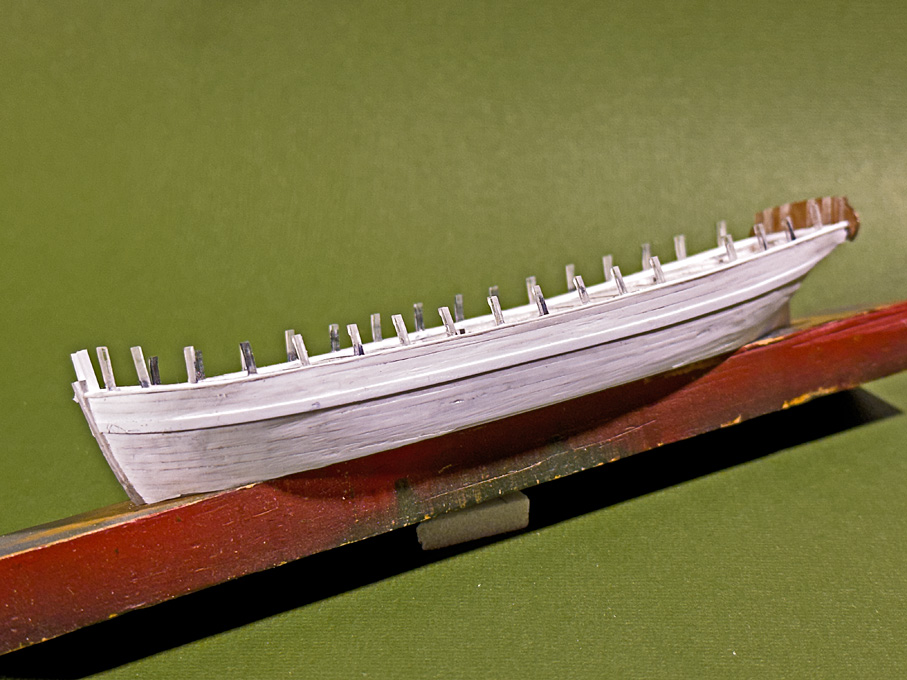
Thanks to all for your continued encouragement ! Slow progress due to business travel-related absence from the workshop ... ************* Planking the bulwarks The planking of the bulwarks follows the same procedure as that for the hull, but had to be handled much more careful, as the inside will be visible and there will by no adjustments possible by sanding or scraping. The main reason for the latter is, that the planks are of scale thickness (0.25 mm) and profiled. Section through a bulwark drawn by Friis-Pedersen (1980). As can be seen from the two images above and below, it was not uncommon to give the edges of the planks a decorative profile by using an appropriate profile plane. Bulwark of a Swedish jagt, photographed in November 2023 in Stockholm I had been exploring various ideas for creating these profiles on tiny 1 mm x 0.25 mm styrene ‘planks’ uniformly and consistently close to the edges. In the end I decided on a simple and rather makeshift solution: a steel ruler was taped to a small cutting-mat to serve as guide for the very flexible strips. The chosen tool is an old-style ruling pen, of which I have several knocking about in my drawer of draughting utensils. This was set so that it creates a groove close to the opposite edge, when run along the edge of the strip. This works only for strips of uniform width. It was important to prevent the styrene strips from softening too much during gluing, therefore only tiny drops of liquid styrene cement were applied to each stanchion. Somehow the alignment of the bulkheads was not as perfect as I was hoping for, resulting in some bulges. I hope I will be able to correct/hide this somehow. Another problem is that the styrene strips of scale thickness are rather floppy, so that edge-alignment is rather difficult. I hope that I can also sort this out. Once the planks were on, I installed the hawse-timbers between the stem and the cant-frames in the bow. Next on will be the rails. To be continued …
-
Ancient Mediterranean Ships, Il Trabaccolo
wefalck replied to OldSaltf's topic in Nautical/Naval History
Yep, have all three, but not the 'Kleber'. The Museo Storico Navale in Venice has a rich collection of Boat models: https://www.maritima-et-mechanika.org/maritime/venezia/museonavalevenezia-2.html and real boats: https://www.maritima-et-mechanika.org/maritime/venezia/museonavalevenezia-3.html from the Venetian lagoon and surrounding waters. -
Fractal vise on kickstarter
wefalck replied to DavidG's topic in Modeling tools and Workshop Equipment
Somewhere in the deep space of YouTube I saw a video on building one. I remember another video on restoring one, where one can see the construction. Sorry no links. In any case, it's a quite evolved piece of equipment. In case this is too expensive or a too daunting task, there are other solutions for holding irregular objects. In the old days the manufacturers of water- or steam-armatures used two-jaw chucks with removable top-jaws that could be milled/turned to fit the object. A low-cost option would be a pot-chuck filled with some heat-softening plastic (hot glue may do), but it only works with metal objects, not wood. -
Ancient Mediterranean Ships, Il Trabaccolo
wefalck replied to OldSaltf's topic in Nautical/Naval History
The second link points to the Web-site of Gilberto Penzo, perhaps the authority on Venetian boats (and a nice guy), where you can buy his drawings and books. A few years ago he published a comprehensive book on the trabaccolo: PENZO, G. (2020): Il Trabaccolo.- 230 p., Sottomarina (Ve) (Il Leggio Libreria Editrice). -
I had discovered decades ago that making half-hitches eases the seizing of blocks etc. a lot and keeps the rounds in place. The only issue is that one can see this on one side, so strategic placing of the 'hitch' to become mostly not visible is a good idea. If you are averse to using an organic solvent-based varnish (e.g. diluted clear nail varnish) for securing rigging, you may want to try the cement they use in nail-studios to stick artificial nails to ladies' real nails. I recently discovered that this is a mixture of CA and metacrylic monomers: it sticks quite fast, but you have several minutes to adjust things before it fully cures. It is not as 'nasty' as pure CA and forms strong bonds. It should be readily available in your part of the world.
- 312 replies
-
- 6
-
-
-
- Chile
- Latin America
- (and 6 more)
-
I thought that she already was part of the museum's collection and that's why you are restoring her in the museum ... Excellent work anyway 👍🏻
-
Indeed, nice attention to and rendering of details! If there was no voice-pipe or telegraph, how did the bridge communicate with the engine-room then?
-
When there are eye-bolts, blocks would be shackled or hooked to them. The blocks would be either internally stropped in metal, or there would be an external strop in rope with an eye for the shackle/hook. The splice or the whole strop could be served and there would be a seizing between the block and the eyelet. I suspect that on a boat like this there may be a few windings of wire replacing the shackle …
- 312 replies
-
- 5
-
-
-
- Chile
- Latin America
- (and 6 more)
-
This is a problem sometimes encountered with plans for modellers of vessels with tumble-home. On ‚real‘ plans two lines would be drawn that may cross each other near the bow and near the stern: one for the outside of the top of the frames (or the rails) and one for the edge of the deck or covering board. They would be marked accordingly.
- 139 replies
-
- 3
-
-
- ancre
- Bateau de Lanveoc
- (and 2 more)
-
We had this discussion in another thread already. Don't mess around with other solvents. Alcohol is the normal solvent for shellac and the cheapest alcohol you can get is normally denatured alcohol. It's being sold under various denominations and depending on country in supermarkets or hardware stores. There should not be a problem in finding it even in alcohol restrictive areas of the world. Shellac solution is not the same as sanding sealer. The latter normaly contains 'fillers', typically either pumice or some sort of clay. The fillers serve to fill the pores of the wood. The 'binders' in sanding sealers can be shellac, some nitrocellulose solution, or more recently also metacrylic acid solutions. So, shellac on its own is a varnish, rather than a sanding sealer. However, on hard woods no filling may be required, so that pure shellac can form the basis for building up a varnished surface. However, you don't want 'varnished' decks normally. Therefore, it is a good idea to rub down the wood treated with sanding sealer or neat shellac using fine steel-wool. This results in a smooth surface with a satin finish, but without an obvious layer of varnish.
-
Leaving a part too long in a blackening solution results in a buildup of several layers, which then can detach, i.e. flake. Using a ‚tampon‘ process means that the surface is exposed to a limited amount of blackening solution, reducing the risk of flaking.
- 732 replies
-
- 5
-
-
- Lula
- sternwheeler
- (and 1 more)
-
I think understanding patterns, such as bedding or fractures that determine weathering forms are important to make this realistic.
-
I am curious to see, how another geologist will treat those rocks! As a geologist I usually find rocks on train-layouts and dioramas quite unnatural ...
-
Buying Filler Blocks
wefalck replied to mikiek's topic in Building, Framing, Planking and plating a ships hull and deck
... and the wood should not be much softer than the bulkheads, otherwise there is a tendency to sand hollows into the fillers, which defeats the object. On the other hand, one can always build up the surface again or apply wood-filler putty. -
A common arrangement for the forestay and the jib-halliard is that the forestay is looped around the mast and the jib-block strop has an eye that goes around the stay just below the point were the loop of the stay closes. The strop is then fiddled from the top through the loop of the stay, effectively forming a kind of cow-hitch around the stay. The picture below is a model picture, but illustrates what I mean: I think your image of the masthead above shows just an arrangement, rather than the one you have drawn. On serving an eye: have you tried to make a 'fake' eye-splice? This mean going with the whole thread going through the thread (with the help of a needle or hypodermic needle) a couple of time and then securing this with a drop of varnish etc. That allows you to serve the splice quietely.
- 312 replies
-
- 7
-
-
-
- Chile
- Latin America
- (and 6 more)
-
Doesn't look too bad at all, but seems to be a quite complex process. What about cored solder of an appropriate diameter? It bends easily without tools (so as not to leave marks) and can be drilled out at the ends as needed. It would also be easily painted black/rust.
- 288 replies
-
- 5
-
-
- Santos Dumont No. 18
- hydroplane
- (and 1 more)
-
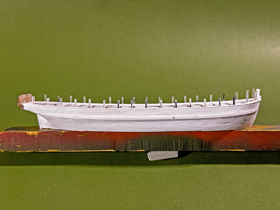
So, here it is ... Planking the hull In principle planking this hull with styrene strips is not very different from planking with strips of wood. The styrene strips have the advantage that they can be more easily bent across the breadth. One can also shape them like metal by stretching and compressing until they conform to the shape of the solid hull. A disadvantage is that they are less stiff than wood and easily ‘sag’ in, say in thicknesses of les than 0.5 mm, but it also depends on the distance between the frames. Planking proceeded up and down from the wales and down from the covering board. The Evergreen styrene strips are sawn from sheets as is evidenced by saw-marks on the narrow sides. This results in slight variations of their width, typically up to 0.1 mm wider for a 1 mm wide strip. This has to be considered, when planning the plank layout. In the end, I didn’t actually use my new plank-clamp much. It was easier to hold the strips short with the edges upright and to scrape the edge with a scalpel to reduce the width in a controlled fashion. There was not much need to bevel the edges. The styrene cement, of course, softens or dissolves the material, which allows it to be pushed together closely, obviating the need for bevelling at least for material of 0.5 mm thickness or less. Unlike for woodworking, not many specialised tools are needed. I use a scalpel, the tools that in the old days was used to rub-on lettering comes handy to press on the strips, a large diamond nail-file for thinning down strips, and cutting-tweezers as watchmakers use them for shortening strips to length. The latter have the cutting edge bevelled only on one side, allowing for clean cuts without squashing the material. I also made small scrapers from a piece of razor-blade, held in a pin-vise. Steel-wool of various grades helps to blend-in parts or lightly round edges. The pictures show the planking after cleaning up by sanding and scraping, but before puttying any gaps that may have occurred. I went for some slight irregularity of the surface, as may be observed in a well-used older wooden ship. This livens up an otherwise somewhat sterile styrene surface. To be continued …
-
In 'normal' rigging practice, one would paired shrouds, but this is 'artisanal' practice and may also be determined by the available lengths of material.
- 312 replies
-
- 5
-
-
-
- Chile
- Latin America
- (and 6 more)
-
FaceBook miniature tools ads
wefalck replied to jmlyle's topic in Modeling tools and Workshop Equipment
The drill-press actually looks very well-made and if I didn't have my antique miniature watchmakers drill-press, I would consider it. However, one should check, whether someone offers a version for ER11 collets, rather than the bulky and likely unprecise drill-chuck. As to the tablesaw (and similar machines on offer), one should perhaps consider them as 'kits in an advanced stage of manufacture'. It may be cheaper to buy such kit and modify it to one's needs, than to buy the individual components. With a bit of effort, these machines can be turned into useful tools. -
Something like that happened to me once: it was dark in the centre of Copenhagen and I reversed my 2CV into an empty slot of a car-park, when my progress was abruptly stopped. I looked into the rear and wing mirrors and couldn't see anything offending, either were there any walls or bollards. I got out of the car and bumped into a huge black candelabre - just couldn't see the thing in the dark.

