


wefalck
-
Posts
6,668 -
Joined
-
Last visited
Content Type
Profiles
Forums
Gallery
Events
Everything posted by wefalck
-
 We had this discussion in another thread already. Don't mess around with other solvents. Alcohol is the normal solvent for shellac and the cheapest alcohol you can get is normally denatured alcohol. It's being sold under various denominations and depending on country in supermarkets or hardware stores. There should not be a problem in finding it even in alcohol restrictive areas of the world. Shellac solution is not the same as sanding sealer. The latter normaly contains 'fillers', typically either pumice or some sort of clay. The fillers serve to fill the pores of the wood. The 'binders' in sanding sealers can be shellac, some nitrocellulose solution, or more recently also metacrylic acid solutions. So, shellac on its own is a varnish, rather than a sanding sealer. However, on hard woods no filling may be required, so that pure shellac can form the basis for building up a varnished surface. However, you don't want 'varnished' decks normally. Therefore, it is a good idea to rub down the wood treated with sanding sealer or neat shellac using fine steel-wool. This results in a smooth surface with a satin finish, but without an obvious layer of varnish.
 -
Leaving a part too long in a blackening solution results in a buildup of several layers, which then can detach, i.e. flake. Using a ‚tampon‘ process means that the surface is exposed to a limited amount of blackening solution, reducing the risk of flaking.
- 732 replies
-
- 5
-

-
- Lula
- sternwheeler
- (and 1 more)
-
I think understanding patterns, such as bedding or fractures that determine weathering forms are important to make this realistic.
-
I am curious to see, how another geologist will treat those rocks! As a geologist I usually find rocks on train-layouts and dioramas quite unnatural ...
-
Buying Filler Blocks
wefalck replied to mikiek's topic in Building, Framing, Planking and plating a ships hull and deck
... and the wood should not be much softer than the bulkheads, otherwise there is a tendency to sand hollows into the fillers, which defeats the object. On the other hand, one can always build up the surface again or apply wood-filler putty. -
A common arrangement for the forestay and the jib-halliard is that the forestay is looped around the mast and the jib-block strop has an eye that goes around the stay just below the point were the loop of the stay closes. The strop is then fiddled from the top through the loop of the stay, effectively forming a kind of cow-hitch around the stay. The picture below is a model picture, but illustrates what I mean: I think your image of the masthead above shows just an arrangement, rather than the one you have drawn. On serving an eye: have you tried to make a 'fake' eye-splice? This mean going with the whole thread going through the thread (with the help of a needle or hypodermic needle) a couple of time and then securing this with a drop of varnish etc. That allows you to serve the splice quietely.

- 312 replies
-
- 7
-
-

-
- Chile
- Latin America
- (and 6 more)
-
Doesn't look too bad at all, but seems to be a quite complex process. What about cored solder of an appropriate diameter? It bends easily without tools (so as not to leave marks) and can be drilled out at the ends as needed. It would also be easily painted black/rust.
- 288 replies
-
- 5
-
-
- Santos Dumont No. 18
- hydroplane
- (and 1 more)
-
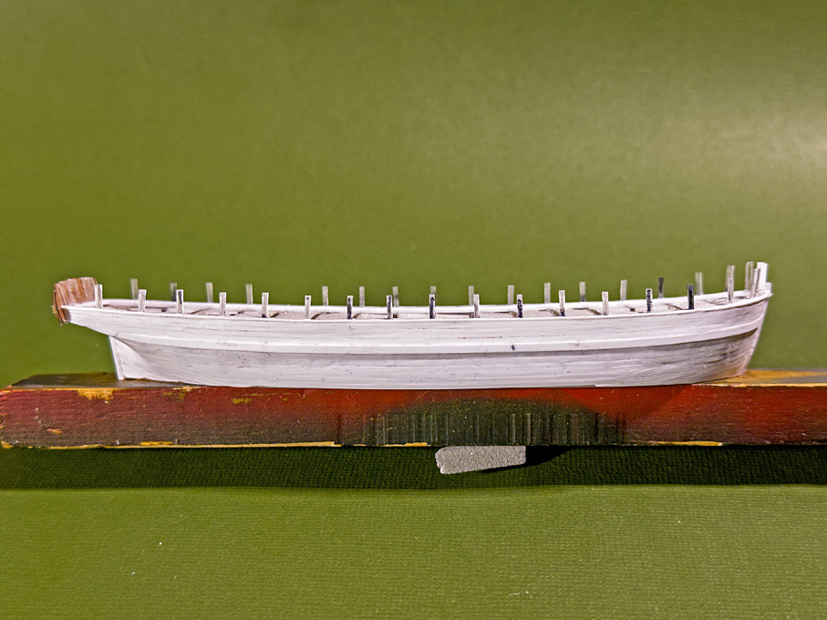
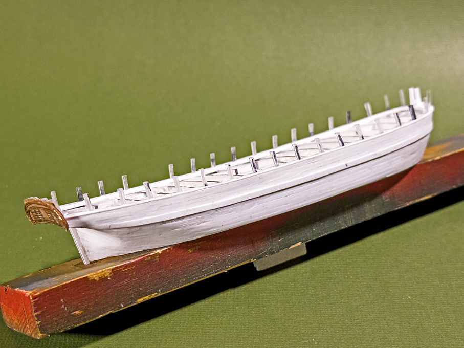
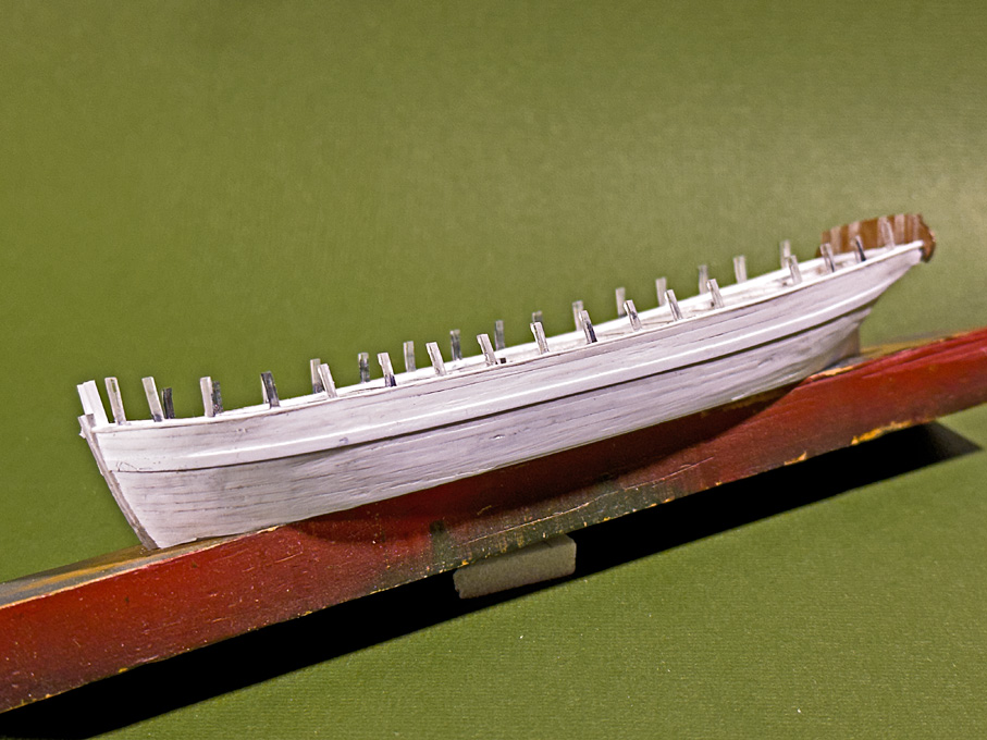
So, here it is ... Planking the hull In principle planking this hull with styrene strips is not very different from planking with strips of wood. The styrene strips have the advantage that they can be more easily bent across the breadth. One can also shape them like metal by stretching and compressing until they conform to the shape of the solid hull. A disadvantage is that they are less stiff than wood and easily ‘sag’ in, say in thicknesses of les than 0.5 mm, but it also depends on the distance between the frames. Planking proceeded up and down from the wales and down from the covering board. The Evergreen styrene strips are sawn from sheets as is evidenced by saw-marks on the narrow sides. This results in slight variations of their width, typically up to 0.1 mm wider for a 1 mm wide strip. This has to be considered, when planning the plank layout. In the end, I didn’t actually use my new plank-clamp much. It was easier to hold the strips short with the edges upright and to scrape the edge with a scalpel to reduce the width in a controlled fashion. There was not much need to bevel the edges. The styrene cement, of course, softens or dissolves the material, which allows it to be pushed together closely, obviating the need for bevelling at least for material of 0.5 mm thickness or less. Unlike for woodworking, not many specialised tools are needed. I use a scalpel, the tools that in the old days was used to rub-on lettering comes handy to press on the strips, a large diamond nail-file for thinning down strips, and cutting-tweezers as watchmakers use them for shortening strips to length. The latter have the cutting edge bevelled only on one side, allowing for clean cuts without squashing the material. I also made small scrapers from a piece of razor-blade, held in a pin-vise. Steel-wool of various grades helps to blend-in parts or lightly round edges. The pictures show the planking after cleaning up by sanding and scraping, but before puttying any gaps that may have occurred. I went for some slight irregularity of the surface, as may be observed in a well-used older wooden ship. This livens up an otherwise somewhat sterile styrene surface. To be continued …
-
In 'normal' rigging practice, one would paired shrouds, but this is 'artisanal' practice and may also be determined by the available lengths of material.
- 312 replies
-
- 5
-
-
-
- Chile
- Latin America
- (and 6 more)
-
FaceBook miniature tools ads
wefalck replied to jmlyle's topic in Modeling tools and Workshop Equipment
The drill-press actually looks very well-made and if I didn't have my antique miniature watchmakers drill-press, I would consider it. However, one should check, whether someone offers a version for ER11 collets, rather than the bulky and likely unprecise drill-chuck. As to the tablesaw (and similar machines on offer), one should perhaps consider them as 'kits in an advanced stage of manufacture'. It may be cheaper to buy such kit and modify it to one's needs, than to buy the individual components. With a bit of effort, these machines can be turned into useful tools. -
Something like that happened to me once: it was dark in the centre of Copenhagen and I reversed my 2CV into an empty slot of a car-park, when my progress was abruptly stopped. I looked into the rear and wing mirrors and couldn't see anything offending, either were there any walls or bollards. I got out of the car and bumped into a huge black candelabre - just couldn't see the thing in the dark.
-
FaceBook miniature tools ads
wefalck replied to jmlyle's topic in Modeling tools and Workshop Equipment
That's why I was asking for some pictures. One can then comment on possible qualities and point to reliable sources. -
FaceBook miniature tools ads
wefalck replied to jmlyle's topic in Modeling tools and Workshop Equipment
Could you post pictures of these machines to better understand what you are talking about? -
Very nice ship's capentry job ! Although on a real boat it would be a lot more physical labour to cut the rabbets, laying out in 1:1 is a lot easier than at a small scale (how do I know this ...).
- 141 replies
-
- 5
-
-
-
- ancre
- Bateau de Lanveoc
- (and 2 more)
-
Makes sense! Thinking about it, it would be also more stable during pushing, as there is less of a cantilever on the rig, than if it was pushed the other way around. I also didn't realise that there was a 'bow' end.
- 732 replies
-
- 6
-
-
-
- Lula
- sternwheeler
- (and 1 more)
-
... equally interesting is the vertically boilered shunter on the photograph. Will you be building one too?
- 307 replies
-
- 10
-
-
Would the pile-driver actually pushed from the side of the rig? I would have expected the tug to be tied up to the other side, also so that the driver can be manoeuvred into position.
- 732 replies
-
- 6
-
-
- Lula
- sternwheeler
- (and 1 more)
-
There have been five auctions since, the last one a few days ago: https://www.premiermachineryauctions.com/auctions/detail/bw134676, and more to come ... Not junk at all, but a lot of most desirable precision machines and associated tooling. The guy most have spent a small fortune on auctions etc. Some of the machines are in quality state rarely seen on ebay & Co. or dedicated machine tool sites. It's a pity that I am on the other side of the Great Lake and have not space anyway 🙄 Didn't we have a thread on this already?
-
Slikspan is the way to go. The sails look very good!
-
OK, this is now a bit of thread drift, but would concern the 'input' side of the grain-elevator. Since around the middle of the 19th century threshing was typically done by contractors, who would travel around the country with their portable steam-engines or their agricultural steam-engines and the the threshing machine in tow. This was, of course, before the days of combine-harvesters. The threshing system could be set-up either on the field or on the farm, depending on when the contractor would arrive in late summer/autumn. The grain would be collected in bags and stored on the farm, or directly transported to the mill (if it had the capacity) or to the station/harbour for shipping. However, I think in Europe grain was mainly locally milled and the flour shipped, but distances were comparatively short. Over longer distances, the grain would be shipped in bulk and milled at the destination. So, bags were used along the way from the field to the point of bulk shipping. From the early 20th century on, even smaller farms may have had their own small threshing machine and a portable hit-n-miss or similar petrol engine to drive it. Or such equipment was shared across the village. The arrival of the combine-harvester seems to have changed this pattern, as they either off-loaded into a lorry dring alongside or were periodically emptied into open lorries that then drove to mill or the shipping point.
-
Well, good for those out in the Far West, who have the space for such scenic settings. We humble urban dwellers have to make do with dioramas or scenes in glass boxes 😞 Where did the power for the grain-elevator come from? Manual labour? In windmills power is taken off the 'main shaft' to drive a winch with which the sacks were lifted to the highest level from which they migrated by gravity through the processing. How would be the grain delivered to the silo, in sacks or loose? Threshing machines in Europe were designed to output into sacks. Perhaps the ramp served both, the hay-barn and the grain-silo. With the carts going half-way up, this would save a lot of labour/energy. The carts would then be unloades somewhere inside the building. Ventilation doors were also my first thought, to prevent dust explosions and to make also the working atmosphere in this enclosed space a bit more comfortable.
-
Their full range for the German market can be looked up here: https://www.vallejo-farben.de/ In the Model Air range they have glossy, satin, and matt varnishes. I think they are also available in larger containers than the usual little bottles. There is nothing to prevent you to use these varnishes pre-diluted for the airbrush with a normal soft brush, I do this quite frequently. I found that the surface sheen is somewhat different depending on whether you use the airbrush or a normal painbrush. If you have the choice, you may need to experiment to the sheen you want.
-
I remember reading the research thread, but somehow missed until now the building log. I am interested in everything that happened on the Seine, after all it flows past in sight from where I live. However, judging from the background on the photographs, I think Santos Dumont must have run his trials on the Bassin d'Argenteuil, a quiet lake-like stretch of the river between two barrages a few kilometres downstream from me. Coming back to the construction material: I also would think that steel-tubes as in bicycles were used. Aluminium tubes would have been extremely expensive at that time, if at all available. There was no welding technique at that time that would have not drawn the temper from the steel-tubes. So, I think they were silver-soldered, as is the practice for steel bicycle frames.
- 288 replies
-
- 6
-
-
- Santos Dumont No. 18
- hydroplane
- (and 1 more)

