


wefalck
-
Posts
6,652 -
Joined
-
Last visited
Content Type
Profiles
Forums
Gallery
Events
Everything posted by wefalck
-
 Perhaps it is helpful to recall how the different types of cement and glue work. Contact cements work due to physico-chemical interactions with the materials and by replacing the air between two parts so that the ambient pressure presses the parts together. For this reason, contact cement is mainly used for cementing together two non-porous materials or a non-porous material to a porous one (think laminate to wood). Because of this, contact cement works best with large surfaces (think again of laminating or veneering). The functioning of the bonds depends thus on the cement remaining slightly 'rubbery' and once all the solvent has evaporated, the bond may fail. Also, contact cement bonds are not very resistant against 'peeling' action. Thinking about these mechanisms and properties, cementing narrow planks that may still be 'springy' may not be an ideal area of application for contact cement, apart from the technical difficulties of applying a uniform film and high pressure. PVA on the other hand works in a completely different way. It forms only weak physico-chemical interactions with non-porous surfaces and therefore is not really suited to bond such materials to each other or to wood. PVA essentially keys into the wood pores of the parts to be glued together and forms a mechanical link between them ones cured. Because of this mechanical link by the cured resin the bond is resistant against peeling and it is typically the wood that fails and not the bond per se. This makes it a good glue, when there is some strain on parts, such as from 'springy' planks - if the parts have been clamped together until the PVA has fully cured.
 -
On most contact cements it is written that the amount pressure applied is important, not its duration. This is why cobblers hammer down soles etc. and C-clamps are used. Both are not so good propositions on a delicate model ship's hull ...
-
... and typically they used what was available. So, one would need to specify, where the ship in question was built. Say, in the Netherland, particularly the Zaanstrek, they had easy access to semi-industrial sawn planks due to the large number of wind-driven saw-mills. In other parts of Europe, there may have been planks sawn in water-driven saw-mills, while in many parts of Europe planks had to be sawn by hand, making them expensive. In general, planks could be rather wide, due to the still relative abundance of large trees, which rapidly declined in the following century.
-
Geologist talking to geologist 🤪
-
This must be actually quite stable rock with little weathering - otherwise I would be worried, that after ice-melt in spring spalled-off rocks drop onto the tracks from the tunnel opening ...
-
Is there any faulting/fracturing in those rocks? On the modern photo it looks a bit like it. If so, these could be added perhaps with some ink washes? Do you leave the pastels as they are, or will you add some 'fixative', as pastel artists sometimes used to do? Otherwise, how will you protect these surfaces in the presumable open layout. I also use pastels, but my models are all stored under glass-covers.
-
On this point: in case you don't have yet protective glasses, watch out for those that look like the ones used by cyclists, they are lightweight, have narrow frames and enclose the eyes because they are close-fitting - much more comfortable than the traditional, big ones. There are also variants that have loupe inserts at the inside lower corners. I found that, as I am getting older, I am wearing more and more another pair that has +3 loupes as glasses. They are bit bigger than the ones above. However, the cyclist-type may now also be available as loupes these days. I bought mine at least ten years ago. One of those pen-type cord-less drills was given to me by my wife as Christmas present a while ago. As they were originally intended for engraving glass, their speed is too high for my taste, thus being quite aggressive. I also find it inconvenient, that it starts with the highest speed and then cycles down. Likewise, I would prefer hands-free control - I run all my machines off foot-switches. Perhaps they should have integrated a voice control
- 139 replies
-
- 4
-

-
- ancre
- Bateau de Lanveoc
- (and 2 more)
-
Yep, I used to do the same eyebolt-ring set up for strength and simplicity. In fact it was done in fullscale practice, where ring served to prevent the wood from splitting, rsther than to carry the ring.
- 312 replies
-
- 5
-
-

-
- Chile
- Latin America
- (and 6 more)
-
If you have a table saw, you can also tape/glue the sheet-metal to a piece of thick cardboard or thin plywood and run them together through the saw. That prevents distortions. And of course, that is lovely construction work in metal and plastics. Very crisp!
-
I think one needs to use one's imagination and also walk around with open eyes in order to see what materials or hardware or tools can be adapted to our needs. I am not familiar with the markets and the accessibility of shops in the USA, but hardware and DIY stores are places of interest, as are shops selling art and architectural model-making supplies, watchmaking and jewel-making suppliers, nail-'art' suppliers, chirurgical/ medical/ dental/ biological instrument suppliers, woodworking and luthier suppliers, antiques dealers, etc. When I am looking for something, I am plugging the respective keywords into ebay and see what somes up and in which trades. I then might browse also the respective stores to get ideas for what is on the market. I then look, whether I can get an item of interest closer to home and at what price.
-
Perhaps, rather than asking how 'should' I prepare sails, a better question to ask is 'what kind of effect do I envisage to achieve' and then think what would need to be done to achieve it, such as stiffening, change in colour, hiding a too course weave, etc. Then try out various materials at your disposal or that you can obtain. Perhaps a fundamental question to ask is also, whether the kit-supplied fabric is really suitable. For all but the largest scales the fabric usually supplied is too thick and has a too coarse weave. Perhaps you also want to look through the several threads here on this forum related to 'silk-span', where there is a quite extensive discussion and references to more realistic and to-scale sails.
-
... or door- or furniture-knobs. You can file the slot to suit your keel and can work them over, if needed, by chucking them up in a drill - I assume you don't have lathe, otherwise it would be easy to make them yourself.
-
pin vise and drill bits
wefalck replied to palmerit's topic in Modeling tools and Workshop Equipment
When looking for tools keep in mind that model shops often have the bad habit of selling cheap stuff at elevated prices to unsuspecting fellow modellers. Most fine tools are not made for us, but are adopted from various trades, such as watchmaking, surgery, dental care, luthiers etc. In the age of Internet, global trade (my sympathy to our US American colleagues) and supply chains, there is no reason not to look for the real source of such tools. Just do a search when you discover a tool and the search engines or auction platforms usually propose a wide selection. It is also a good idea to browse the (on-line) catalogues of the above mentioned trades to get an idea for what tools are available and what their price range may be (attention: medical stuff may be expensive, but often you can find 'seconds' on the Internet at lower prices that are good enough for our uses). I not normally use a pin-vise for drilling, there are tiny single- or double-action Archimedean drills for watchmakers that do a better job and clamp down to 0.1 mm, if you get a good one. I gather there are four types of pin-vises on the market: the all-steel toolmaker ones with knurled bodies, the slender watchmaker ones with steel jaws, but often a fluted brass body, the watchmaker ones with exchangeable collets (not sure what the point is, it is better to have a set of pin-vises handy), and the biological ones that are steel, but have a fluted ebenony handle. In addition, you get the cheap modeller ones with brass jaws and/or eloxated aluminium bodies. The larger toolmaker ones (e.g. Starret or Eclipse) are bored 2.5 mm, so can hold the common burrs and other tools with the same 2.4 mm shaft diameter, such as triangular scrapers etc., which could be useful for deburring and other tasks. Not sure whether there are pin-vises bored for 1/8" for the Dremel bits. I posted the picture below before, but it can give you an idea of what is on the new and second-hand market: 1 - Archimedes drill for watchmakers. 2 - Slender modern pin-vice with hollow fluted brass body. 3 - Slender antique pin-vice with hollow fluted brass body. 4 - Shop-made pin-vice with walnut body and head made from an insert drill-chuck; these drill-chucks are unfit for their intended purpose as they usually do not run true. 5 - Eclipse toolmaker's pin-vice with knurled steel body; these come in different sizes. 6 - French-style pin-vice; these are closed with the sliding ring and have usually brass inserts in the two jaws that can be adapted to special needs; 7 - Dito, here the jaws are replaced in hardwood for delicate parts. 8 - Antique laboratory pin-vice with fluted wooden handle. 9 - Modern pin-vice with fluted wooden handle; these come in different sizes and capacities. 10 - Antique toolmaker's pin-vice for very delicate work in confined spaces.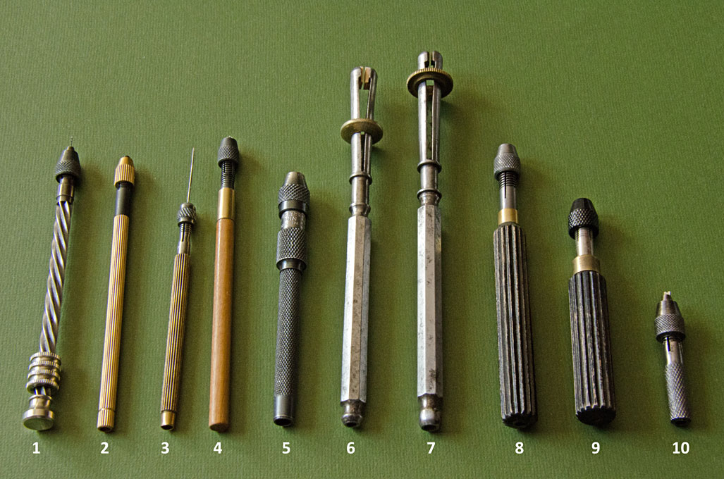
-
Thanks for your comments @mcb! It is actually the 'old' duroplastic material invented by Baekelundt. It is essentially one or more layers of paper soaked in phenolic resin and cured between steel plates to ensure uniform thickness and a mirror-like surface. It is still used for electrical insulation and certain types of PCBs, a class called FR-2: https://en.wikipedia.org/wiki/FR-2. It is available from thicknesses from 0.1 mm up to 6 mm or even in blocks and rods (usually with cotton-fabric, rather than paper). I got a life-time supply about 30 years ago from a specialised dealer in Berlin, who sold it by the meter. You can find suppliers on the Internet (including on ebay). Most of the material seems to be produced in India and China these days. It glues very well with CA - some 25 years ago a made little clinkered boat with bakelite-paper planks glued with CA and it still looks pristine. For larger flat pieces I also used zapon-varnish, which adheres well. The edges of the bakelite-paper are quite brittle, so care and sharp tools are needed, when cutting it. It sands well with fine diamond nail-files.
-
Thanks ... the Bakelite-paper is semi-transparent, so that indeed parts underneath are shining through. After painting (eventually), nothing will be seen anymore.
-
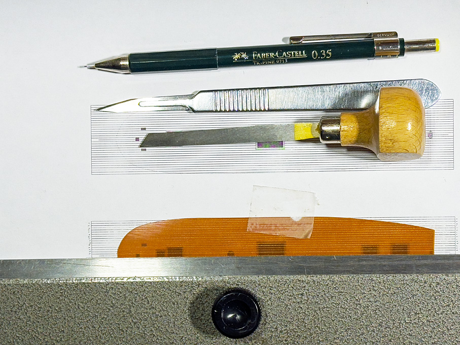
Thanks, gentlemen, for your continuing encouragement and the many 'likes' ***************************************************************************** Fitting the deck The deck is made from 0.4 mm thick Bakelite-paper. I find it easier to engrave the deck-seams consistently into this harder material with my tools, then into the softer styrene sheet. Perhaps I should get some day one of those hooked engraving tools the plastic modellers use (I have the suspicion these are the same tools as dentists use to scrape of ‘plaque’ – I have one of those and perhaps should have tried). I first printed out the deck-drawing, cut out the shape and fitted it to the ship. Using the paper template, the shape was cut from the Bakelite with a small margin. This then was fitted very carefully in an evening’s session. Fitting started from the stern working forward, taking off material with a diamond nail-file while checking the fit after a couple of strokes. A tight fit is important, as the whole idea is to paint the deck off-ship to avoid a complex masking exercise. Also, the painting process (as described in the build-log for SMS WESPE) would be difficult to exercise within the constraints of the bulwark. Tools used for engraving the deck seams The fitted deck was taped to a printout of the deck with the planks marked as guidance for engraving. A heavy steel ruler ensured straight lines. First, the plank seam was marked with a scalpel to provide some ‘tooth’ for the graver. Then a narrow engraver’s graver was run twice along the ‘seam’ to clean out the shallow groove. Once the engraving was completed, the whole deck was thoroughly brushed with a rotary bristle-brush to remove burrs. I ended up doing this three times, as in the first two attempts I lost count and cut a skewed seam. This is unrepairable, so I had to start all over again. However, the first fitted deck provided a good template, speeding up the fitting process: after scoring the material with a scalpel around the edges of the template, one can break the new deck out of the bakelite sheet. Only comparatively little fitting was required then. In fact, scoring the bakelite-paper with a scalpel twice and then breaking along the line is a quick and clean way of getting straight cuts that just require a bit of sanding with a diamond file. The next step would be to cut out the openings for the companionways and hatches. However, these have to be tight fits to them and it will be easier to first build those and then file out the openings – back to the drawing-board for some time. To be continued …
-
Oops, missed the continuation of this new project ... have been travelling too much the last few weeks. When I used very thin copper-sheet to simulate hull plating and pouncing the rivets, I found that rubbing them down from the front with a cork (Champagne corks work best, because of their round lower edges and sort of integrated handle) reduces the distortion of the sheet and gives a more realistic look. I have not tried the same with styrene sheet. Not sure that it would work, because it is less malleable than copper, but it may be worth a try. Another material that I have used is this self-adhesive aluminium tape that is used to cover up the seams in dry-walling. However, I have used it only only represent rivetted reenforcement strips, not larger surfaces, as I am a bit weary of self-adhesive materials - the adhesive film might dry out and become brittle with time.
-
Perhaps you could use cardboard-templates to work out the geometry?
- 139 replies
-
- 5
-
-
- ancre
- Bateau de Lanveoc
- (and 2 more)
-
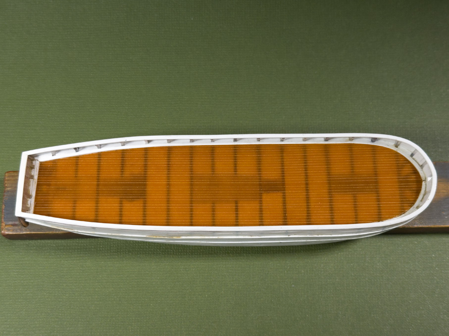
You are absolutely right, the 'caboose' as a temporary deck fixture was very common between the early decades of the 19th and about the last quarter of it. They were usually lashed down onto the deck with one or more iron (or wooden) bars over their into which iron rods were hooked or screwed. When they were hooked, the rod had ring at the lower end and a lanyard between this ring and an eye-bolt was used to lash it down. The other option was to hook the rod into the eye-bolt on deck and tighten the threaded rod down with a nut at the upper end. Below is an example from a German museum model: One also see this kind of arrangements on early photographs of sailing ships from both sides of the Big Pond. Caps and companionways as such where not necessarily permantly fixed to their coamings, but may have been removable to be stowed away under deck, e.g. when really severe weather was expected. In this case the opening would be closed with a simple lid that was less prone to be washed away and thus give water access to the interior of the ship.
-
BTW, decks should not be 'varnished', decks were always left bare wood on the prototype. If you use varnish or sanding filler, you should rub down the deck with very fine steelwool, so that no visible varnish layer is left on the surface.
-
Another option would be sheet brass. Strong structures can be build from very thin sheet bent and soldered together. When one sticks it to thin plywood or MDF, it can be sawn easily and precisely without distortions. Personally, I think (nearer to) scale thickness is greatly enhancing the look when structures are hollow and with a lot of see-through windows in them.
-
Well, people tend to confuse 'scale' with 'size'. It doesn't really matter at what scale you are working, the size of features, both small and large can matter ... Obviously, the thicker the material, the more difficult it is to cut it with a scalpel. On the other hand, with thin material, it is more difficult to correct cuts by filing or sanding. If you are working at 1/200 scale a sheet of 0.02" (=0.5 mm) thickness would translate to walls o 4" (= 100 mm) thickness, which would be quite formidable, even if in wood. So chosing thinner material will make your life easier from a cutting point of view. Perhaps you should reconsider your construction technique. I assume that you use the styrene sheet as structural material, i.e. you are building a hollow structure? Unless you want to show some interior details, it may be a good idea to build a structure from wood or thicker styrene and clad this with 0.01" styrene sheet into which you can cut the window etc. openings. For me the reason to use styrene sheet would be mainly that it looks more like steel when painted, than most efforts of filling and sanding wood. When laying out the styrene for cutting, I would use a sharp scriber to mark the window openings. The scribed lines form a guide for the scalpel cut, even if you use a ruler. Make an incision in the corners first from both sides in order achieve crisp corners.
-
As a side-comments (an perhaps in the case of a kit one cannot do much about this), deckshouse do not sit on the planking. Rather, they are anchored into the structure of the ship through the coamings and the deck-planks are running up to them.
-
New York may be the same latitude as Naples, but they don't have there the Alps to keep the winds from the North Pole away 🥶 ... reminds me of a Christmas there many decades ago, when we had -30°C due to the chill-factor.
- 732 replies
-
- 3
-

-
-
- Lula
- sternwheeler
- (and 1 more)

