


wefalck
-
Posts
6,661 -
Joined
-
Last visited
Content Type
Profiles
Forums
Gallery
Events
Everything posted by wefalck
-
 Machining bevel gears it not trivial and one needs a pretty massive 'universal' milling machine or shaper and a dividing head for that. However, by 1900 it would not be uncommon to see bevel gears of some sort on steam-engines. For instance, they were used since the later 1860s or so to drive the rope-drums on ploughing engines. Also, they became increasingly common in engineering due to the budding automotive sector, although there initially chain-drives were used. Chain-drives were used on (sailing) ships for instance to power winches from a centrally placed IC engine, but also in stationary industrial applications powered by steam. From the modelling perspective, one could turn a cone and file the teeth for bevel gears. You can buy them down to 0.3 modular, but that would be still too coarse for your scale. For chains, one could try to find a so-called fusee-chain as used in certain types of clocks/watches, but I have no idea of prices.
- 457 replies
-
- 3
-

-

-
- sternwheeler
- Hard Coal Navy
- (and 1 more)
-
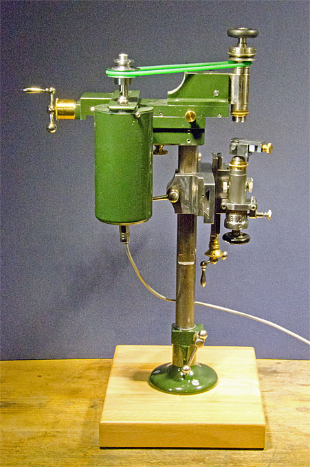
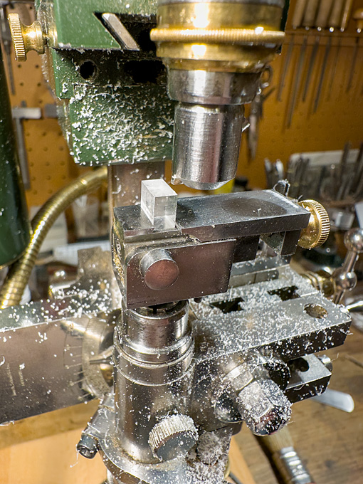
Well, it's a vintage milling machine that never was: https://www.maritima-et-mechanika.org/tools/micromill/micromill.html. The key mechanical parts came from antique watchmaking lathes. https://www.maritima-et-mechanika.org/tools/micromill/MF-V1.mp4 The miniature vice is shop-made: https://www.maritima-et-mechanika.org/tools/attachments/attachments.html#Micro_vice
-
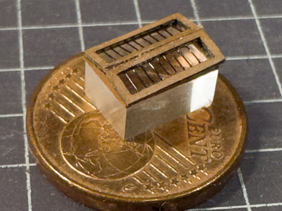
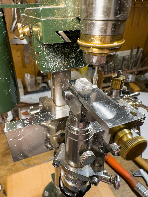
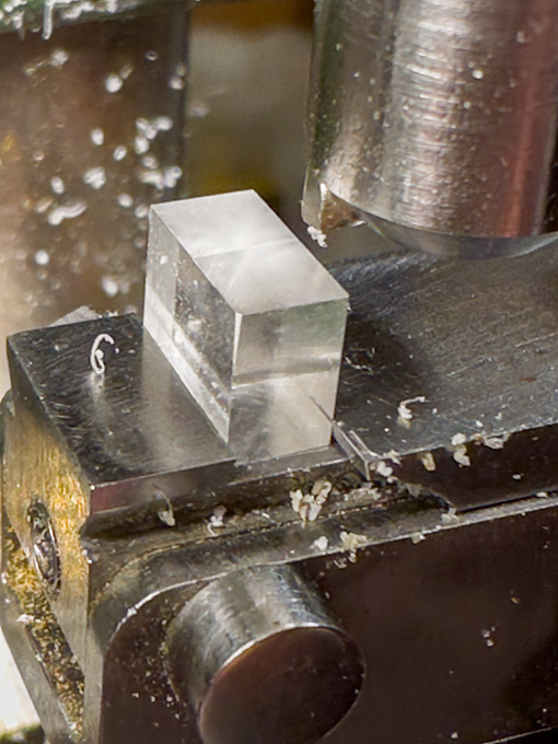
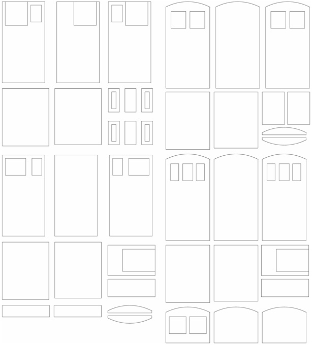
In between business-related absences from home, I managed to progress a little bit ... **************** Cabin Skylight As noted previously, the cabin skylight is a somewhat perilous position, but nevertheless contemporary drawings and some old models indicated, that they were of relatively lightweight construction. The actual construction is somewhat conjectural, but it seems that the hatch was covered by frame into which glass-panes were insert. Over this, there is a shallow roof-like structure with protective iron bars. In this arrangement, the glass-panes are not actually insert into the roof-like structure, but are at some distance below. The effect is, that even in the event that the iron bars are bent, the glass would not be touched. It also conceivable, that in the Baltic not real glass was used, but rather muscovite, which would be obtained by trade from Russia. In the event of very bad weather, the roof-like grille presumably could be replaced by a plain hatch cover. Milling to shape of the acrylic glass core for the cabin skylight This structure was built up in my preferred way, that is around a core of acrylic glass. It was milled to size from scrap piece of acrylic glass. For the ‘glass’ surface, I was able to use one of the original - as manufactured - surfaces, so no polishing was required. The high-speed milling with a fly-cutter a low feed-rate left almost transparent surfaces. Milling to shape of the acrylic glass core for the cabin skylight Milling of the recesses for the laser-cut frame parts The parts for the roof-like structure were produced again with the laser-cutter from Canson paper. The structure was to be designed in two parts, namely the frame attached to acrylic core and the two roof halves with the grilles, to allow painting. During painting the horizontal pane will be masked off and the roof halves painted separately. In order to ensure equal spacing of the ‘bars’, the roof was built up from three layers with the middle layers having notches. This layer was lacquered onto one of the outer layers and the ‘bars’ attached with drops of varnish – quite a fiddly bit of work and I am not entirely satisfied with the result. In the past, I made such parts from surface-etched brass and this seems to have worked better, but I didn’t want to set up everything for etching just a couple of small parts. Basic structure of the skylight, waiting to be painted and finally assembled I prefer to defer painting to the late stages of the building process in order to avoid handling the painted parts as much as possible, so construction of the skylight stops here for the moment. To be continued …
-
... well, I studied in Zürich and one of my friends came from a family, who were 'in' aluminium 😁
-
Impressive 'engineering' work 👍🏻
-
Actually, it was not completely finished, I still have to arrange properly the glass case and some brass plaques …
-
I am pleased to see that my suggestion worked 😇 Looking at the anchor in the photograph, it looks quite 'shop-made' by someone, who did not really understand, how these anchors work, just roughly copying their shape. In theory, the stock is a bit thicker on one side of the shaft and secured from slipping through the hole in the shaft by a removable pin. When the pin is removed, the stock can be pulled through and rests flat against the shaft for storing, which is why it is bent 90° at the end. The stock also has a sort of ball at the end, preventing it from being completely pulled out. Your anchor is a very good representation of this home-brew version!
- 312 replies
-
- 5
-
-
-
- Chile
- Latin America
- (and 6 more)
-
Thank you very much, gentlemen, for your kind words! @JacquesCousteau I have been trawling various museum image databases and national meta-databases in Denmark, Sweden and Norway with keywords such as jacht, jagt, jægt, schlup, slup, sloop etc. Unfortunately, German museums are not so advanced in digitising their holding, though there are meta-databases at Länder level in Schleswig-Holstein and Mecklenburg-Vorpommern. Vorpommern, Swedish Pomerania until the Vienna Congress in 1815, is now in Germany, while Hinterpommern, originally Prussian, is now part of Poland. I didn't have access to Polish database in this respect, though they do a good job in digitising their archival holdings it seems. The problem is also, that both parts of Pomerania were rather marginal areas with comparatively little industry and trade and thus wealth, so they did not attract that many painters or later photographers. In consequence, the pictorial records until the late 19th century are quite limited - at least judging by what is available in books and on the internet. @Bedford Such gratings do not appear on any builders drawings at that time. This may be a weak argument though, as they are not structural parts of a ship. My anecdotical feeling is, that they only appear, when wheel-steering became more common, even in smaller vessels. I could imagine, that they would not support much sideway pressure, as would be needed when handling a tiller (though relief tackles were common). They also do not appear on any contemporary models of small merchant vessels. Later photographic evidence supports arrangements as seen on the Norwegian jægt above. Many of such small vessels had a quarterdeck raised by a foot or so (a 'roof') with the skylight inserted into this and the tiller just clearing it. The helmsman would stand in front of the raised quarterdeck. However, these Pomeranian Rahschlups were characterised by a flush deck.
-
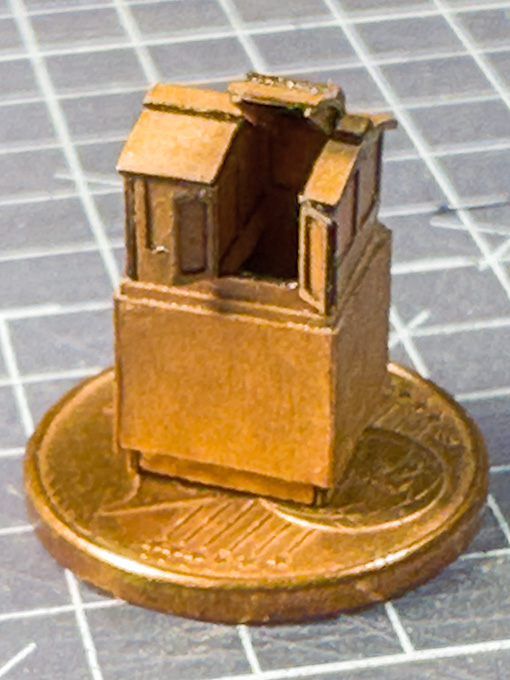
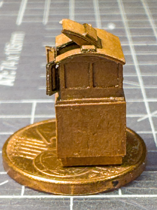
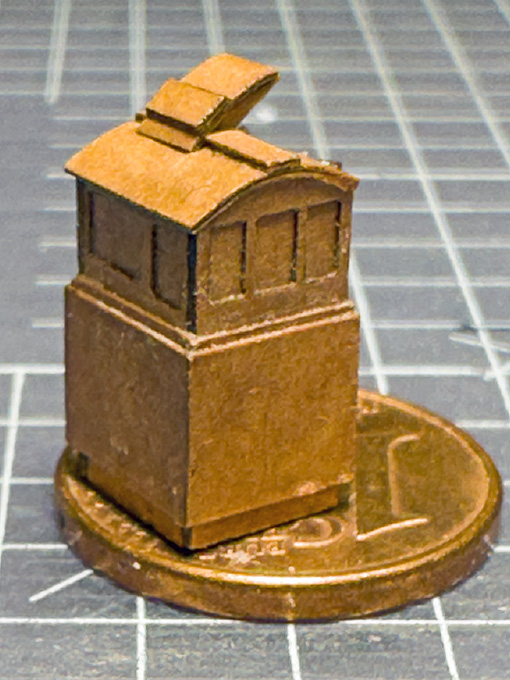
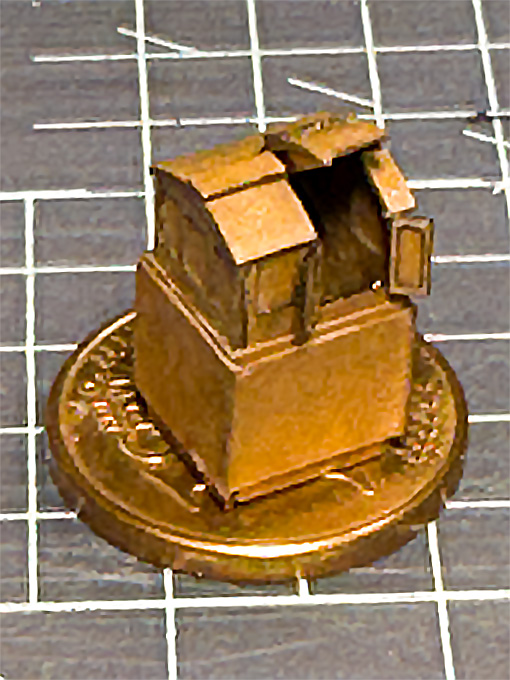
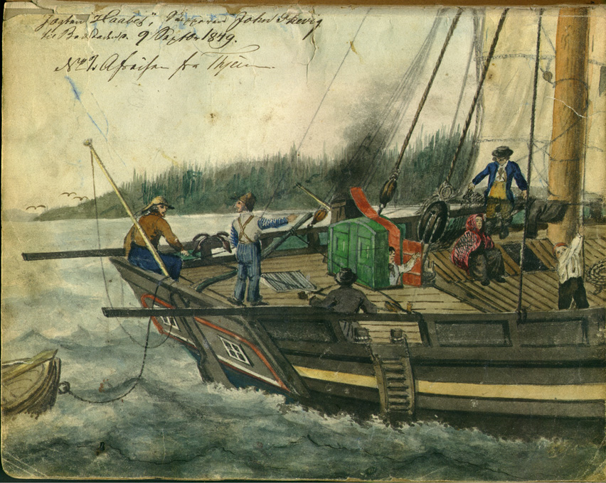
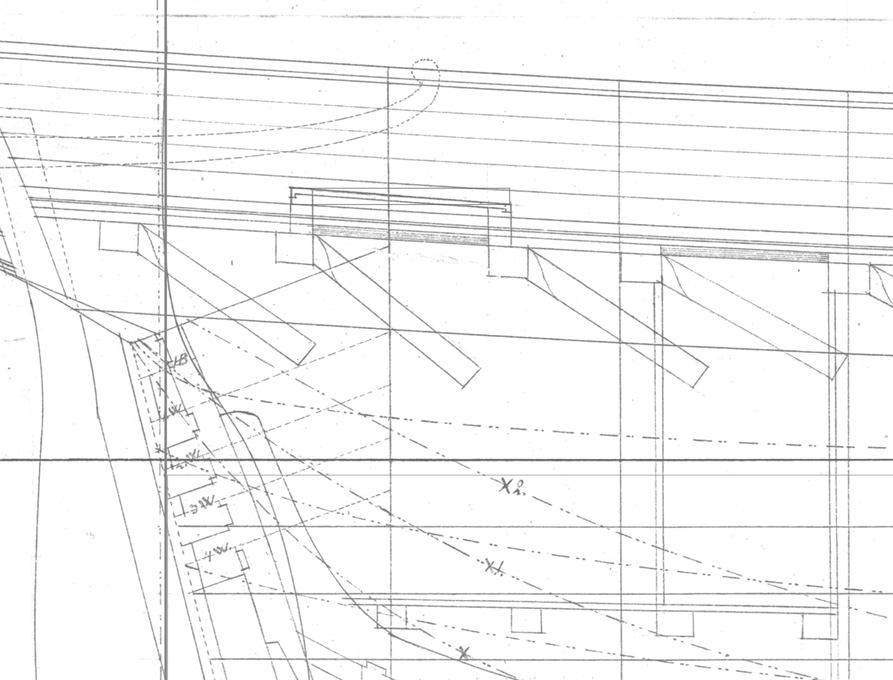
Cabin companionway and binnacle The layout of the access to the stern cabin is somewhat puzzling, even taking into consideration that accommodation in this kind of vessel was spartanic and cramped. There seems to be a skylight over the cabin that was most probably protected by a grille. However, it is just in the area over which the business end of tiller sweeps. The helmsman would have to pay attention, where he puts his feet. Rather close in front of it seems to be the companionway that leads down into the cabin. Unlike for the other deck openings no coamings are drawn. Normally, there would have been a movable binnacle behind the companionway, so that the helmsman has a good view. The binnacle at that time was constructed like a cabinet and would be lashed down to the deck. However, the space between the skylight and the companionway seems to be too narrow to accommodate this kind of cabinet. Details of the stern arrangements, original drawing by Möller (1846) By looking through contemporary paintings and drawings of similar vessels, I chanced upon a somewhat naïve watercolour of a local painter from Trondheim, that shows a combination of binnacle and companionway. It also opens in a somewhat unusual fashion, where a segment of the roof is hinged to flip backward – rather than the usual sliding cover. Not sure how this would behave in any kind of stronger wind. Not all the details and the perspective in the watercolour seem to be right, but overall, it looks credible. The whole arrangement is actually quite similar to that of the original drawing, also with the skylight right under the tiller, which actually is worked quite casually with ropes by the gentleman with straw(?)-hat sitting on the port stern rail. Anyway, I opted for this solution as it is unusual and solves the space problem. As a bonus I don’t need to worry about rendering the lashings of the binnacle. The Norwegian jægt HAABET (1849). Source: Town archives of Trondheim - https://www.flickr.com/photos/trondheim_byarkiv/3539132719. The companionway-binnacle combination was again built from laminations of laser-cut pieces. The main objective was to show the panelling. So, each side was built up from three layers, the outer ones simulating the frames with the cut-outs for the panels. The profiled coamings were simulated by adding two further layers. The collection of parts for laser-cutting Assembly of all those parts was a bit of fiddling and I prefer my usual method of assembling companionways etc. around a solid core milled from a piece of acrylic glass, but this obviously only works, when they are shown closed. To be continued …
-
The figure-of-eight knot is the classical knot that one puts on the end of line to prevent it from running out through blocks et. I learned this already 50+ years ago during my first sailing lessons. It becomes a habitual gesture to put one on, as soon as one has reeved a line through a block. This has not be confused with the 'stopper-knot' that was used to attach shorter lengths of rope to anchor-cables inboard to relief spills etc. when riding at anchor.
-
A 'waste' well used! When I had a (blond) beard for a while, I used trimmings from it to represent the stubbs on a winter-field.
-
Normally, one should get threaded rod from M3 (or imperial equivalents) upwards. Cutting such rods with a hacksaw is easy and one can use a file to bevel the ends of the rod so that the nuts fit over them. If you have one, you can also use a small triangular file to clean up the threads - they have the same 60° angle (or perhaps 55°, if imperial threads).
- 139 replies
-
- 4
-
-
- ancre
- Bateau de Lanveoc
- (and 2 more)
-
Consider it storm-damage ... sailors were good at fixing things while under way ...
-
I have used saw-dust: put some white glue on the sticks in blotches snd then roll in saw dust. When dry paint to the bark colour.
- 312 replies
-
- 5
-
-
-
- Chile
- Latin America
- (and 6 more)
-
That makes perfect sense 👍🏻
-
As in the case of purchasing any kind of machine tool, it is useful to make a list of fundamental specification and capabilities needed: - Which are the maximum dimensions of parts I want to produce? - What is the maximum thickness of materials I want to work with? - What kind of materials do I want to work with? - What sort of operations I want to do, i.e. cutting out 2d-objects or sculpting 3d-objects (2-axis router vs. 3-axis milling machine) - What is the spatial resolution needed? - Do my objects have have to have sharp corners or can I live with or hand-treat rounded corners? Then also a list of possible constraints is helpful: - Do I have the surface space to permanently accomodate the machine ? (moving it around may cause alignment issues) - Do I have the possibility to vent out fumes? - Do I have connections for cooling water? (needed for some types of lasers) - When do I want to work with it re. nuisance due to noise produced by routers - How can I manage dust? 'Sculpting' with a laser in principle is possible by modulating the power and/or the lengths of pulses and the number of repeated passes. However, it always will result in charred surfaces and removing the charred wood form small intricate parts can be difficult, particularly when one wants to have the 'real' wood surface in the end. On the other hand, the laser works 'contact-less', which is particularly useful for very small and delicate parts.
-
Never heard the term 'guest-rope' before, but seems to make sense for something a boat crew could hold onto while coming alongside. However, in such a case, I would have expected the hope to be running more or less horizontally, while on virtually all the pictures one end is tied up to the bottle-screws or thereabouts. I know that yachts-people sometimes jump ashore and grab the shrouds to pull their boat towards the quay, but I am not so sure that would work for a 150 ton schooner. Otherwise the 'guest-rope' could help in such endeavour. However, I would rather expect one man to jump ashore and another throwing the mooring line to him, with which the ship could be coerced more safely towards the quay. A puzzle ...
-
He doesn't take a breath before starting a new project ... Good thing that this is a historic ship, otherwise one would wonder, whether it would stay afloat long enough to complete the model 😲
- 457 replies
-
- 4
-
-
-
- sternwheeler
- Hard Coal Navy
- (and 1 more)
-
The darker colour shows that the linesee oil penetrates deeper, while the water-based sealer stays more on the surface. The oil penetrates into the pores and acts as a kind light conduit deeper into the wood, similar to fibre optics, so less light is reflected and hence the wood appears darker. Water-based sealers do not penetrate so well, as wood is naturally somewhat hydrophobic, even wood that does not contain much resin, like cherry. That's why I am still using solvent-based sealers ... as long as one can get them.
- 312 replies
-
- 5
-
-
- Chile
- Latin America
- (and 6 more)
-
Topsail schooner sail plans and rigging
wefalck replied to Dr PR's topic in Masting, rigging and sails
Well, I think this thread is interesting (apart from the fact that a topsail-schooner is on my project list), because it shows the wide variety of possible arrangements. I may have said this before: we tend to be too framed by naval practices and rules, and by yachting 'rules', which in turn had been strongly influenced by naval costums. In the merchant navy anything that worked was permitted. If it didn't work, it silently disappeared or, when it involved an accident, it may have been branded as bad practice in court, leading to the master loosing his patent. Also, when we see a particular arrangement in historical photographs, we don't know, whether this was an arrangement of the moment or a permanent feature. On the other hand, too much variation and to many fancy arrangements would have been probably counterproductive in an industry, where the workforce often changed frequently. Sailors on larger ships typically stayed only for one roundtrip. On coastal vessels they may have stayed for years. The point is that a sailor coming on board newly will have to 'learn the ropes' of this particular ship and may grab the wrong one in situations of stress. So it would be good practice to have not too many differences from ship to ship.- 104 replies
-
- 1
-
-
- schooner rigging
- Topsail schooner
- (and 1 more)
-
Nice to see an Omani craft being built here. Since a couple of visits in to Oman in 1989/90 (I had a friend working there in the oil industry, there were not tourist visas yet), I got interested in their craft. On the design of the stern: on their way around Africa and further to India, the Portugues arrived in Oman in the later 16th century and established a base there. The forts in Muscat were originally built by them. The local shipbuilders began to copy the design of the European hulls then. They never adopted the European square rigs though, as the settee-sail (which is four-sided, as opposed to the three-side latin sail) was much better suited to the seasonal trade driven by the monsoon. Typically an annual round-trip was made from Oman down to East Africa/Zanzibar, then across to India and back to Oman. African slaves were transported from Zanzibar a major trading hub for them directly to Oman. Wood was a major commodity imported from India, as there is virtually no boatbuilding wood available in Oman. While big trading dhows are now extinct, small trading and fishing dhows are still being built, but not in Oman anymore (though there is still a yard in Sur I think), only in modern Tanzania (incl. Zanzibar mainly) and Kenya. Here are some photographs of dhows and dhow-building in Dar-es-Salaam and Zanzibar: https://www.maritima-et-mechanika.org/maritime/tanzania/tanzania.html. For those interested to dive deeper into the matter, I have some reading suggestions: Dhow Bibliography Agius, D.A., Cooper, J.P., Zazzaro, C. (2014): The Maritime Heritage of Yemen: A Focus on Traditional Wooden ‘Dhows’.- In: Agius, D.A., Gambin, T., Trakadas, A [Eds] Ships, Saints and Sealore: Cultural Heritage and Ethnography of the Mediterranean and the Red Sea: 143-157, Oxford (Archaeopress). Agius, D.A., Cooper, J.P., Zazzaro, C., Jansen van Rensburg, J. (2014): The Dhow’s Last Redoubt? Vestiges of Wooden Boatbuilding Tradition in Yemen.- Proc. Seminar Arabian Stud., 44: 71-84. ANONYM (1979): Oman, a Seafaring Nation.- 196 p., Sultanate of Oman (Min. of Information and Culture). ARGYLE, E.W. (1954): The Ancient Dhow.- Seabreeze, New Ser., XVIII: 262-5. LE BARON BOWEN, R. (1949): Arab Dhows of Eastern Arabia.- Rehoboth, Mass. Carvalho, F. da Piedade (2014): Os Dhow do Zanzibar: A técnica de construção de uma antiga embarcação de origem árabe e o seu papel socioeconómico na actualidade.- Cadernos de Estudos Africanos, 27(6): 149-170. DOI: 10.4000/cea.1535. CHETHAM, M. (1950): Dhows in East Africa.- Country Life, CVIII: 1803-7. De Leeuwe, R. (2004): Seascape and Sailing Ships of the Swahili Shores.- MA Thesis: 123 p., Leiden (University of Leiden). De Leeuwe, R. (2005): Constructing Sailing Ships on the Swahili Shores.- Azania: Archaeological Research in Africa, 40(1): 107-113. De Leeuwe, R. (2006): Swahili Ships in Oceanic Perspective.- Sails of History: Citizens of the Sea, ZIFF Journal No. 3: 45-52, http://www.swahiliweb.net/ziff_journal_3_files/ziff2006-07.pdfK Ennion, H. (1963): Along the Shores of the Gulf of Oman.- Country Life, CXXXIII: 1265-6. ‘FULAHIN’ (1928): Coasting East Africa by Dhow.- Blue Peter, V: 449-52. FALCK, W.E. (2013): Boote und Bootsbau in Tansania, Teil 1: Dauen und Einbäume in Dar-es-Salaam.- Das Logbuch, 49(1): 27-30, Köln (AK Historischer Schiffbau). FALCK, W.E. (2013): Boote und Bootsbau in Tansania, Teil 2: Bootsbau auf Sansibar.- Das Logbuch, 49(2): 62-65, Köln (AK Historischer Schiffbau). FALCK, W.E. (2014): Boats and Boatbuilding in Tanzania (Dar-es-Salaam and Sansibar).- Int. J. Nautical Archaeology, 43(1): 162–173. GILBERT, E.O. (1997): The Zanzibar Dhow Trade. An Informal Economy on the East African Coast, 1860-1964.- PhD Dissertation: 340 p., Boston (Boston University). HAWKINS, C.W. (1977): The Dhow – an illustrated history of the Dhow and its World.- 143 p., Lymington (Nautical Publishing Co.). HORNELL, J. (1941): The sea-going mtepe and dau of the Lamu Archipelago.- The Mariner’s Mirror, 27: 54-68. HOWARTH, D. (1977): Dhows.- 159 p., London (Quartet Books Ltd.). Issa, A.A. (2006): Dhows and Epidemics in the Indian Ocean Ports.- Sails of History: Citizens of the Sea, ZIFF Journal No. 3: 63-70, http://www.swahiliweb.net/ziff_journal_3_files/ ziff2006-09.pdf JEWELL, J.H.A. (19762😞 Dhows at Mombasa.- 103 p., Nairobi (East African Publ. Ho.). MONDFELD, W. (1979): Die Arabische Dau.- 93 p., Bielefeld (Verlag Delius, Klasing & Co.). MOORE, Sir A. (1940): Notes on Dhows.- The Mariner’s Mirror, 26(2): 205-13. SASSOON, C. (1970): The Dhows of Dar es Salaam.- Tanzania Notes and Records, 71:185-199. SHERIFF, A. (2010): Dhow Cultures of the Indian Ocean. Cosmopolitanism, Commerce and Islam.- XV+351 p., (). SPARKS, W. (1909/10): A Muscat Dhow.- Yachting Monthly, VIII: 263. SULIVAN, G.L. (1873): Dhow Chasing in Zanzibar Waters and on the Eastern Coast of Africa. Narrative of Five Years’ Experiences in the Suppression of the Slave Trade.- X+453 p. VILLIERS, A.J. (1940): Sons of Sindbad – An Account of Sailing with the Arabs in their Dhows.- Villiers, A.J. (1954): Passage in a Red Sea Dhow.- The Mariner’s Mirror, 40: 171-82. Villiers, A.J. (1961): Vanishing Ships – Arab Dhows.- British Petroleum Shield, 5: 6-8. VOSMER, T. (1993): The Omani Dhow Recording Project: Sultanate of Oman.- Indian Ocean Review, 6(2): 18–21, Perth. VOSMER, T. (1997): Indigenous Fishing Craft of Oman.- Internat. J. Nautical Archaeol., 26(3): 217-235. VOSMER, T.A., MARGARIT, R.A., TILLEY, A.F. (1992): A Survey of Traditional Vessels of the Sultanate of Oman. The Omani Dhow Recording Project. Field Reasearch 1992.- Department of Maritime Archaeology, Western Australian Maritime Museum, Report No. 69: 80 p. WEISMANN, N. (1994): Der Beden-Safar – Eine Rekonstruktion nach Unterlagen von Admiral Pâris.- Das Logbuch, 30(3): 160-67. WEISMANN, N. (1995): Ein Fischer-Beden in Qurm (Sultanat Oman).- Das Logbuch, 31(4): 175-82. WEISMANN, N. (1996): Der Beden-Seyad – Ein Fischerboot des Omans im letzten Jahrhundert.- Das Logbuch, 32(4): 175-80. WEISMANN, N. (1998): The Cargo-Beden Al-Khammam.- Internat. J. Nautical Archaeol., 27(3):237-257. WEISMANN, N., STAPLES, E., GHIDONI, A., VOSMER, T., DZIAMSKI, P., HAAR, L. (2014): The Battīl and Zārūqah of Musandam, Oman.- Int. J. Nautical Archaeol., 43(2): 413–435. WIEBECK, E., WINKLER, H. (2000): Segler im Monsun. Die Dau am Indischen Ozean.- 130 p., Rostock (Neuer Hochschulschriftenverlag). WISEMAN, W.F (1994): Modeling a Ninth-Century Arab Dhow.- Nautical Res. J., 40: 5-17. YA’QUB, Y. Al-Hiji (2001): The Art of Dhow-building in Kuwait.- 164 p., London (The London Centre of Arab Studies). Tim Vosmer and Norbert Weismann are probably at the moment the most knowledgeable persons on Omani dhows.
