


wefalck
-
Posts
6,652 -
Joined
-
Last visited
Content Type
Profiles
Forums
Gallery
Events
Everything posted by wefalck
-
 On harder woods I use single-sides razorblades as scraper (the ones that have a reinforced back). However, getting things smooth around knots may indeed be difficult. What would help is to treat the surface with a sanding-sealer. That would harden the soft fibres around the knot, making sanding/scraping easier. Another good way to smooth the surface is the use of different grades of steel-wool in between coates of sanding-sealer. However, there is no point then applying lineseed-oil, as it would not penetrate the wood treated with sanding-sealer. There may not need to be a need for further treatment, as the wood treated with e.g. cellulose-based sanding-sealer and rubbed down with fine steelwool takes on a nice satin shine.
- 312 replies
-
- 5
-

-
- Chile
- Latin America
- (and 6 more)
-
Very nice indeed 👍🏻 Did you sculpt the figures yourself? They are very well animated.
- 77 replies
-
- 1
-
-
- Royal Yacht
- card
- (and 1 more)
-
Use Paasch‘s ‚From Keel to Truck‘ and forget about GoogleTranslator …
-
Well, the 'hog-chains' are there to prevent exactly that, the 'hogging' of the boat. It has the same function as the girders/trusses on a bridge above the way. Shallow hulls without (external) keel may not have sufficient strength against bending/hogging, so they need these trusses in the same way a girder-bridge needs them. These trusses are not necessarily chains, but could be iron rods or connected wooden beams. A girder structure of wooden beams could be hidden in the constructional arrangements of superstructure without being so obvious as in the old-time river-boats. Extending the trusses/hog-chains beyond the pivotal pole of the derrick, however, could limit its range of movement. So I would doubt that in a real case they would have been extended further, though from a mechanical point this would be advantageous.
- 732 replies
-
- 4
-

-
-
- Lula
- sternwheeler
- (and 1 more)
-
Well, real life's necessities come in our modelling way - even as pensioners it seems. Good that you can see light at the end of the tunnel. Builders always take longer than they originally claim they would. I have something like that lurking behind the horizon as well ...
-
Sorry for having tread this loose ... you could run a pair of chains (or solid bar stays) from the forward end of the canopy over the boiler further forward, say towards a point at the hull left and right of the mast.
- 732 replies
-
- 4
-
-
- Lula
- sternwheeler
- (and 1 more)
-
This is indeed how the trusses are led on riverboats and other shallow boats that do not have a strong keel as backbone. Incidentally, such trusses already occur on ancient Egyptian boats ...
- 732 replies
-
- 7
-
-
- Lula
- sternwheeler
- (and 1 more)
-
Yep, installing chains properly tensioned is not so trivial, as they do not stretch. On the other hand, in full-scale they have the same problem and one would normally have a turnbuckle there. Looking at the design, I was wondering, whether there shouldn't be another set of chains on the other side of the deckhouse - its structure alone would not be able to balance the strain from the sponsons, I think.
- 732 replies
-
- 5
-
-
- Lula
- sternwheeler
- (and 1 more)
-
Topsail schooner sail plans and rigging
wefalck replied to Dr PR's topic in Masting, rigging and sails
I think, I have seen representations where the forecourse on the lee-side is brailed up, as it would blanket the foresails, but here it is clearly a triangular sail set (flying) to windward. One thing I noticed is that we tend too framed by navy rules and regulations, where everything was supposed to be done 'by the book'. In the merchant navy the master basically could do whatever he saw fit and if it worked, the better. If something went wrong, however, he may have had to explain himself in front of a court. So in practice, one probably saw all sorts of strange arrangements. -
There is a lot of hype about AI and no one usually knows what it really means 🤪 I am using ChatGPT quite a bit in work to get an overview over a subject that I don't know (very well) to give me directions where to dig deeper. It gives the sources now, so one can verify them. The subject coverage seems to be quite variable still, with niche subjects, like ours, being hit-and-miss - as more people ask the right question the system learns and begins to return better answers. ChatGPT becomes really a challenge for our university teaching - while unreferenced Google results were relatively easily to detect (by a Google search 😉), this has become now more difficult. I changed my tactics and tell my student to use it explicitly 😈. When I first plugged my exam questions into ChatGPT, I was flabbergasted, that it came up with the correct answers, even for things on which the students normally failed ... One needs to cascade through various rounds of refinement when posing questions to either Google or ChatGPT in order to arrive at more probably results. Nevertheless, I don't use it very often for our subject area (yet). Back again to LULA now ...
- 732 replies
-
- 6
-
-
-
- Lula
- sternwheeler
- (and 1 more)
-
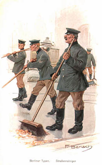
Sorry, I don't want to dilute the thread, but I am curious, when a broom would be a 'push-broom', rather than just an ordinary wide broom? Below is an image of Berlin street-sweeps from around 1910, who seem to push fairly wide brooms:
- 732 replies
-
- 6
-
-
-
- Lula
- sternwheeler
- (and 1 more)
-
Topsail schooner sail plans and rigging
wefalck replied to Dr PR's topic in Masting, rigging and sails
I have seen triangular forecourses, but set in the middle of the yard, with the foot pivoting on an eyebolt in the deck. I think in German it is called 'Faulenzer' = idler. It was used on courses werde frequent gybing was required, as it involves less work. Haven't seen such half-forecourse, however, before. -
A distance diagnosis on the wood is difficult ... Looking forward to how you will walk the tightrope between imitating the haphazard look of the real thing and an unintended look of shoddy workmanship.
- 312 replies
-
- 4
-
-
- Chile
- Latin America
- (and 6 more)
-
This attention to historic detail is just exemplary ... 👍🏻
-
May the idea of firing at an angle is a bit overrated. In order for the guns to be effective, the ships had to be so close together that it didn't really matter at what angle you fired, there would be something to hit in almost any direction. In addition, the movement of the ship made precise alignment of the gun quite futile in practice. For chasing guns the situation might be different. In any case, firing such guns under battle conditions was almost as dangerous for the gun-crews as for those that may have been on the other side of the gun. There wouldn't have been much space on a gun-deck to stay out of the way of a recoiling gun and any whiplashing tackle.
-
I gather it depends on the master and his safety consciousness ... there are/were well-kept boats and others ...
- 732 replies
-
- 4
-
-
- Lula
- sternwheeler
- (and 1 more)
-
That's an interesting utilisation of secondary mineral resources this dredging in Susquehanna. However, their coal-washing upstream must have been pretty wasteful and I am not sure about the environmental impact of both, discharging of large amounts of suspended matter and the dredging of the river bed ... What always fascinates me are these makeshift and improvised vessels (and logging trains for that matter) in the USA. We don't seem to have seen such things to that extent in Europe judging by the pictorial records. As a modeller you can let your creativity run free.
- 732 replies
-
- 6
-
-
- Lula
- sternwheeler
- (and 1 more)
-
"... and pile it as haphazardly as possible on the deck." ... well that would be a hazard and would not normally be done unless a ship is temporarily moored to a quay. Everything that can move needs to be tied down, otherwise it may be lost or become a threat to the crew when shifting around. The crew would do this in their own interest.
- 732 replies
-
- 5
-
-
- Lula
- sternwheeler
- (and 1 more)
-
TT-scale model railway suppliers may have sets of domestic animals, including dogs and cats ...
- 732 replies
-
- 4
-
-
-
- Lula
- sternwheeler
- (and 1 more)
-
You could add a dog - smallish dogs where often kept on board, as alarms against trespassers and to keep vermin at bay.
- 732 replies
-
- 4
-
-
- Lula
- sternwheeler
- (and 1 more)
-
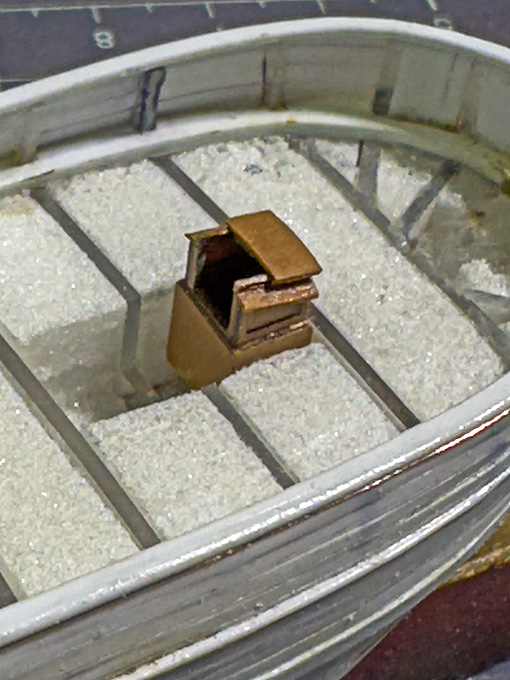
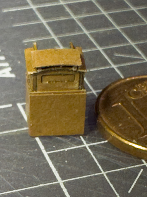
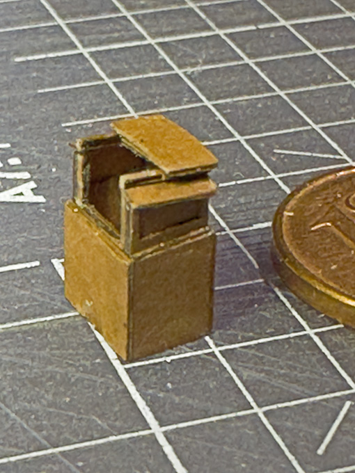
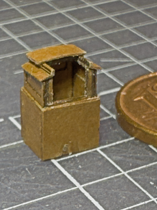
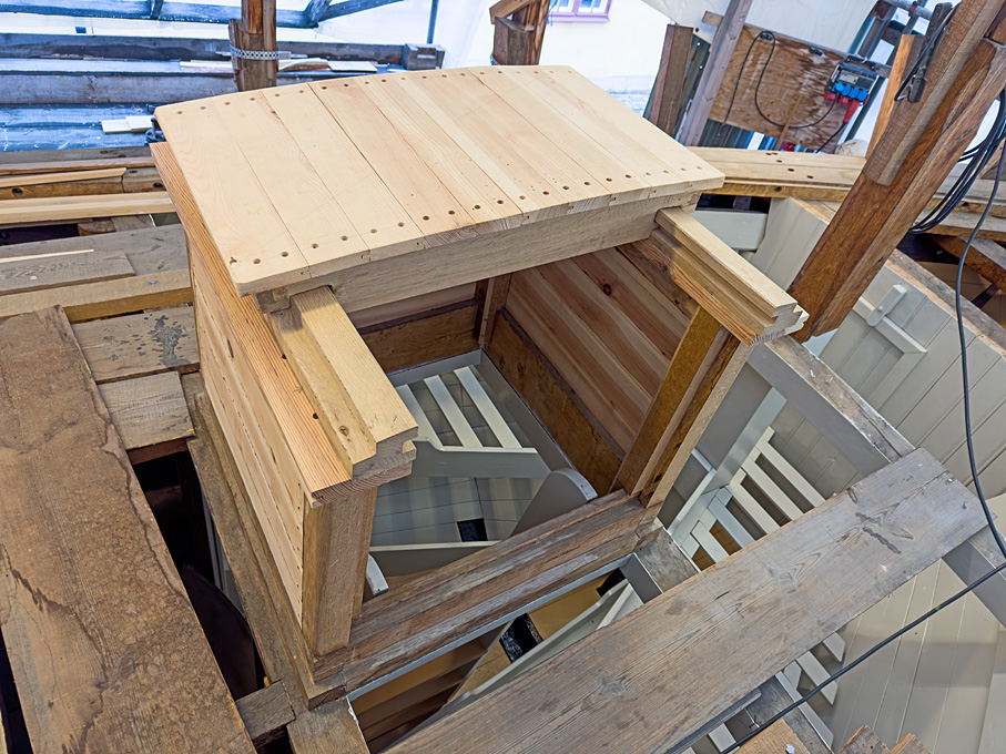
Crew companionway The deck of the Rahschlup was flush, no raised quarterdeck or any deckhouses as such. Only companionways gave access to the crew quarters and the after cabin respectively. All in all, a very spartanic arrangement. Companionway on the reconstruction project for the galeas FÖRLIG WIND, Skeppsholmen, Stockholm (https://www.arbeitskreis-historischer-schiffbau.de/mitglieder/ontour/bootsbauplatz-skeppsholmen/) The length of the companionways and of the hatches can be taken from the side elevation drawing, but their width has to be inferred from common practice of the time. Likewise, their construction had to be inspired by photographs of appropriate restoration projects. A typical construction method seems to have been panelled sides. Other examples include simple vertical or horizontal staves that fill the space between the corner posts. Two narrow doors give access, together with a sliding roof section. The rails on which this cover slides seems to have been of varying degrees of complexity. I usually built such companionways around a core in Plexiglas that has been milled to shape. For this project, however, I wanted to show them open with some interior details, so that a construction method somewhat closer to the prototype had to be chosen. The different parts were drawn and cut out with the laser-cutter from 0.1 thick Canson paper. Each side was laminated from three layers for the actual companionway and two more layers for the coamings using Zapon varnish. The roof and the sliding cover were built up from two layers. The sliding rails were constructed from narrow laser-cut strips. The doors are also built up from three layers. Unlike on the prototype, the companionways and ‘coamings’ reach down to a horizontal layer in the hull in order to provide a reference for their height above the deck, when installed. As with all such parts, they may look a bit rough in the close-up pictures, but once painted and from a normal viewing distance they look very good (hopefully …). To be continued …
-
I gather this is always the dilemma: in real life, things were not always as neat as one may wish, particularly in the merchant navy with few crew; then on the other hand, if one reproduces it on a model, it may look like shoddy workmanship ...
-
Well, our models usually look far too much 'ship-shape, Bristol-fashion'. If you look at photographs, there is usually a lot of clutter and equipment on deck. Alone well-kept navy ships may present themselves well-ordered with everything at its place. The 'clutter' just adds realism.
- 732 replies
-
- 7
-
-
- Lula
- sternwheeler
- (and 1 more)
-
Good to see that both, the model and its maker coming along well !
- 732 replies
-
- 4
-
-
-
- Lula
- sternwheeler
- (and 1 more)
