


wefalck
-
Posts
6,652 -
Joined
-
Last visited
Content Type
Profiles
Forums
Gallery
Events
Everything posted by wefalck
-

Did I ruin my brush?
wefalck replied to MBerg's topic in Painting, finishing and weathering products and techniques
There are different formulations of acrylic paints. Some only use water as 'medium', while others may have a mixture of water and some kind of alcohol. Some may also contain some sort of detergent to reduce the surface tension of water (aka as 'flow improvers'). So, the 'thinner' should be compatible with the 'medium' used in the paint formulation to prevent coagulation. I doubt that with pure water one would be able to clean out acrylics from a brush. You need something that encapsulates the binder molecules (the acrylic resin) that otherwise have the tendency to stick to the hair of the brush (which indeed is their purpose). This is a fairly complex physico-chemical process and normally some sort of detergent ('soap') is used. I was given a pot of 'brush soap' by my wife, but historically have used washing powder for wool. The latter is a mild detergent designed to not damage the natural animal hair (i.e. the wool). -
Agreed. I have the feeling the hitches were suggested by the model instructions because it seems easier than making seizings ...
-
This is presumably a way to stop the lanyard and to stow excess length of it - a kind of seizing done with the lanyard itself. I would feel more comfortable with a couple of real seizing though. Perhaps this was done on real ships.
-
I wish you a steady hand, and strong arm- and back-muscles to see you through this part of the project 👍🏻
-
Did I ruin my brush?
wefalck replied to MBerg's topic in Painting, finishing and weathering products and techniques
I have used synthetic brushes from the DaVinci range with acrylics for decades and always was quite happy with them. Not sure what brands you would get in Canada. I gather the scaly surface structure of natural hair helps to keep more paint in the brush than the smooth synthetic fibres. This can be useful, when painting long lines with round brushes and in similar situations. I actually also bought flat synthetic brushes from cheap Chinese sources and they are very soft and elastic, good for painting larger areas. In general, I do not buy round pointed brushes on-line, but prefer to test the point in the shop myself (with a bit of spit between the fingers ...). On the other hand, if you buy on-line from a reputed supplier and you can show that a branded product does not form a proper point, they will replace it (at least in my experience). The reason for buying on-line in the latter case was, that neither of the two or three art supply-shops here in Paris had undamaged brushes in their racks. People do not pay attention, when putting the protective sleeves back and break or bend hairs 😡 BTW it is not the water that damages natural hair brushes, but the solvents and detergents used to clean them. After all, the highest quality brushes for watercolour painting are the Kolinsky sable brushes already mentioned by @druxey. -
I like this 'banged together'-look, gives you a real impression of a hard working boat. We tend to make our models often to yacht-like, probably to show off our modelling skills.
- 312 replies
-
- 4
-

-

-
- Chile
- Latin America
- (and 6 more)
-
Did I ruin my brush?
wefalck replied to MBerg's topic in Painting, finishing and weathering products and techniques
This is a recommendation by manufacturers (e.g. DaVinci) and art materials supply-houses. No explanation given, but I assume that the detergents and solvents used to clean out acrylic paints may damage the natural structure of the hair - raising the scale-like structures of the hairs, making them rough and less pliable. Ask your wife about using too aggressive shampoo ... -
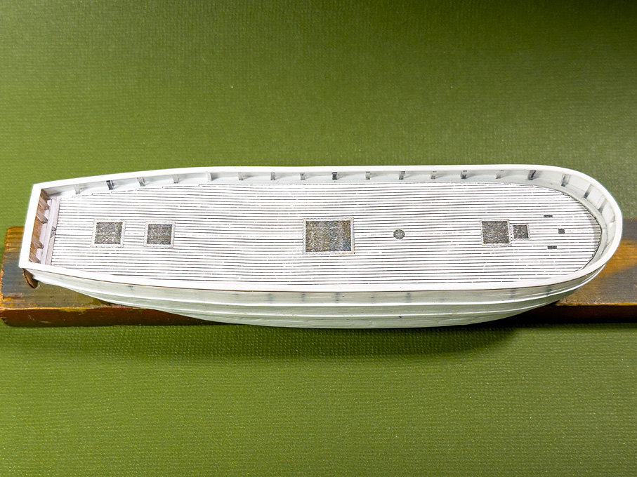
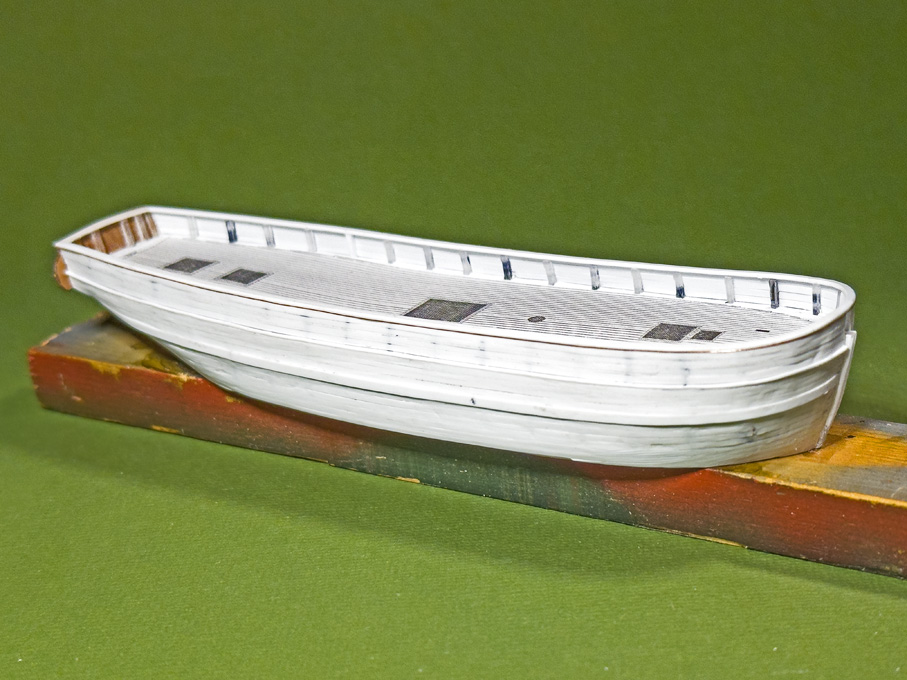
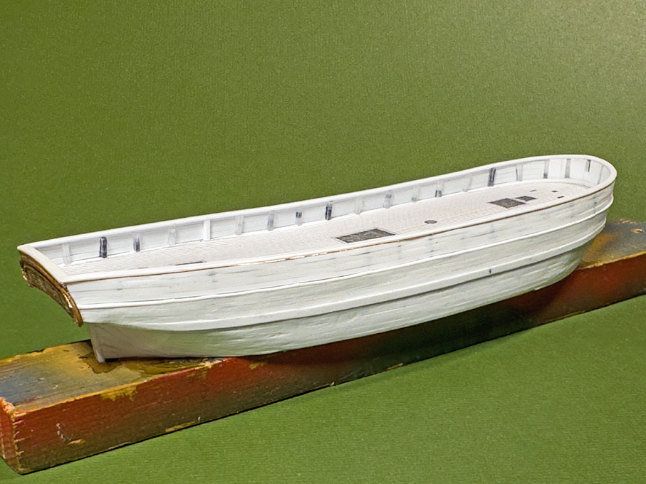
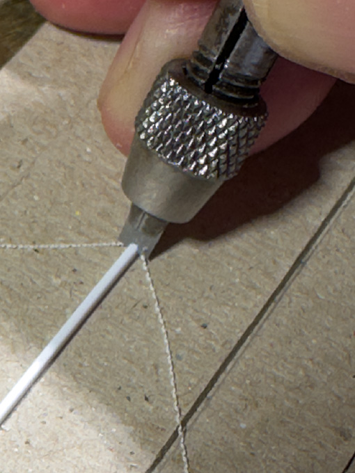
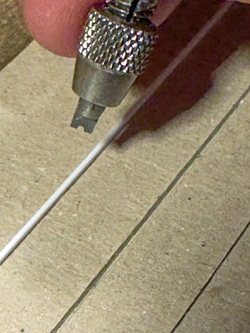
Thanks for the 'likes' ! *********************** Fitting the rails The rails are 0.75 mm x 1.50 mm styrene strips on top of the bulwark and a 0.75 mm x 2.00 mm strip over the stern. The edges of the strips are rounded. To this end I cut a scraper from a piece of razor-blade which is held in a short pin-vice. The strip is held in a simple jig made from cardboard. Strips of cardboard were cut with clean and vertical edges and glued to a cardboard-base so that styrene strips of 0.25 mm, 0.50, and 0.75 mm thickness can be wedged into the resulting notch, holding it straight and vertical. In this way a clean and uniform profile of the styrene strip can be achieved quickly. The styrene strips then were pre-bend, holding them lightly in round-nosed pliers and by ‘massaging’ them around my thumb to make them conform to the sheer-line as closely as possible. They then were glued onto the stanchions and the top bulwark strake using styrene-cement. As can be seen from the cross-section shown in the previous post, the profile of the rail may be even more sophisticated with some cornice planed in. I simulated this my lacquering a 0.1 mm copper wire into the outboard corner under the rail. The next step will be puttying up any small gaps that have developed during the planking process. As one can see on the pictures, I also started to work on the deck by making a paper template for it. To be continued …
-
Very intricate and detailed structure. Love these kinds of details 👍🏻
-
Did I ruin my brush?
wefalck replied to MBerg's topic in Painting, finishing and weathering products and techniques
BTW, acrylic paints should not be worked with natural fibre brushes, such as sable, but with synthetic fibre brushes. -
Mohogany plank bending
wefalck replied to Bontie's topic in Building, Framing, Planking and plating a ships hull and deck
In fact, the heat is the key aspect. Water is mainly used to prevent the wood from burning, when doing the bending over an open fire (as was done in the old days). The steam in steam-chests serves mainly as a carrier for the heat - the heat-capacity of steam is much higher than that of air. As we now have heat-guns readily available, this is probably the best option. -
Did I ruin my brush?
wefalck replied to MBerg's topic in Painting, finishing and weathering products and techniques
I don't want to question the professionalism of Jack's son, but I would have doubts using a wire brush on an artist's hair-brush. The hairs are just too delicate. It is quite normal that paint wicks into the hair inside the ferrule, even if you don't dip the brush down to the ferrule into the paint. As long as the solidified part does not extend beyond, this has no practical consequences. The best advice for getting the paint out of the ferrule was already given above: the appropriate solvent. It is also quite normal that a wet flat brush looks like in the picture above. Once clean and dry, the hairs will separate again. Personally, I find brush-painting acrylics over larger surfaces quite difficult. Perhaps a 'retarder' can keep the paint longer workable, resulting in better surfaces. I normally use an air-brush. -
Mohogany plank bending
wefalck replied to Bontie's topic in Building, Framing, Planking and plating a ships hull and deck
... until they become pliable 😁 ... It depends inter alia on their tickness. -
What oil to use for Proxxon TBM220 drill press
wefalck replied to vaddoc's topic in Modeling tools and Workshop Equipment
Actually, lubricating the quill of the TBM is really a light application, neither high speeds, nor high pressures or temperatures are involved ... -
Buying Filler Blocks
wefalck replied to mikiek's topic in Building, Framing, Planking and plating a ships hull and deck
That's a good idea to keep subsequent strakes together and prevent some sagging, but not really an alternative to the fairing aid of fillers between bulkheads. If the bulkheads are not faired properly, you might still kink the planks. -
What oil to use for Proxxon TBM220 drill press
wefalck replied to vaddoc's topic in Modeling tools and Workshop Equipment
Ordinary 'sewing-machine oil' will do (as per the recommendation by PROXXON at the beginning of the thread). You only want to have the outside of spindle lightly lubricated, but don't want to get it into the ball-bearings. -
A good 40 years ago, when Dremel was not really available on the European market and PROXXON only just started to develop, I bought a cheap hand-held drill that basically consists of a 6V motor with ball-bearings to the axle of which a threaded brass sleeve is screwed. The brass sleeve serves as socket for spring collets. This simple tool has served me well through all those years. The key feature are the steel collets (similar to the one PROXXON offers), because they are much smaller than a drill-chuck, have less run-out and can bear side-pressure. The drill is run off a transformer with an electronic speed control. Now the Chinese are flooding the market with similar designs for hand-held mini-drills, but the quality seems to be inferior - basically they use brass collets of varying quality. Virtually all drill-presses for those hand-held drills I have seen are too flimsy to do real work. The most solid one is the one by PROXXON, but it takes up more space also. I don't have one, but would concour with Waldemar that the PROXXON hand-held drills have probably the best price/quality ratio , but may not be available in Mexico/USA.
- 139 replies
-
- 5
-
-
-
- ancre
- Bateau de Lanveoc
- (and 2 more)
-
Buying Filler Blocks
wefalck replied to mikiek's topic in Building, Framing, Planking and plating a ships hull and deck
I don't know this NRG-article, but the point about filling the spaces between the bulkheads is, that in general in POB construction, in particular in kits, is that the bulkheads are spaced too far apart. This makes fairing the edges of the bulkheads difficult and can also lead to sagging or kinks in the planks, if they are proportionally to thin for the distance. What you use as filling material is not really important, but it should not be harder than the material of the bulkhead to keep the effort of fairing at a reasonable level. Too soft is not good either, because than their is a risk of creating hollows, which defeats the object. Some kit manufacturers offer a sort of remedy for too far spaced bulkheads by providing for two layers of planking. However, you have to get the first layer right, otherwise it transmits all fairing issues to the second layer. -
Are you sure that this is a steam-dome, that thing before the cab? To me it rather looks like the 'coffee-pot' housing for a double set of spring-loaded safety-valves that is seen on early locomotives (perhaps before the 1880s). this 'coffee-put' should be open on the top to let excess steam escape upwards. The thingy on its top looks very much like a steam-bell, rather than a whistle. Some early locomotives didn't actually have steam-domes, but the steam was taken from a high area of the boiler, which is why the boiler has a wider diameter near the cab - not a terribly good solution, as water might get into the steam-pipes on an incline. It is interesting to see that the sandbox sits, where on more modern locomotives the steam-dome would be located, i.e. in the middle of the boiler, where the water level would change very much, regardless whether you were going downhill or uphill. On the other hand, I have zero knowledge of US American steam locomotive practices ...
-
Buying Filler Blocks
wefalck replied to mikiek's topic in Building, Framing, Planking and plating a ships hull and deck
Up to you and what materisl you have to hand … -
Looking for ideas for work area
wefalck replied to Desertanimal's topic in Modeling tools and Workshop Equipment
I suppose the configuration depends on what kind/size of projects you envisage to work. The island configuration may be useful for projects that are too big to shift easily around a work-desk or similar. Otherwise, like in a kitchen, it takes up a lot of floor-space. Check out the dimensional recommendation of the kitchen guys. You typically need 80 cm between working surfaces, so the size of island plus 80 cm around it on all sides. Normal work-benches/kitchen-tops are 60 cm deep, while shelves need 30 cm to 40 cm. My ideal solution would be to have 60 cm work-tops running all along the walls with 40 cm hanging cupboards to the ceiling above. The space in between would be used for hanging tools that have to handy. The space under the work-top I would subdivide into workstations, separated by chests with drawers. However, I am working seated on small projects and all my small machines. It's nice to sit in front of a window and ok for working on small parts, draughting etc., but it is not so good to have a large model between yourself and the window, as you would be working on the 'dark side' of the model. If you are mainly working with artificial light, this doesn't matter, of course. -
One detail puzzles me a bit, that the timbers that carry the transom are sitting on the deck. That seems to be a somewhat unusual arrangement. Normally, deck planking goes around any structural parts.
-
Would be a pleasure, but have to see, whether I am around. Even during the summer I seem to have a lot of business travels this year. We should get in touch via PM a bit closer to the time. Sometimes I see the river cruises pass up or down the Seine from the kitchen window, but now the trees are gettting leaves again and begin to obscur the view ...
-
Just out of curiosity: are you talking about the Vallejo acrylic putty sold in bottles like their paint?
-
The purpose of 'joggling' of planks is to facilitate caulking: the point would be difficult to caulk, because it is likely to break off, when you drive in the cotton with the caulking iron. However, no 'real' caulking would be needed on wooden decks laid over steel-decks. I would be sufficient to fill the seams with pitch/marine-glue. The wooden decks are a sort of sacrificial protection of the steel-decks, make them less slippery, provide thermal and acoustic isolation for the spaces underneath.

