wefalck
-
Posts
6,652 -
Joined
-
Last visited
Content Type
Profiles
Forums
Gallery
Events
Everything posted by wefalck
-
 I think I would have had a cardiac arrest while the first paint went on ... Loosk like my favourite green, British Racing Green or RAL 6007 Bottle Green. Difficult to get these days, but I had it mixed up in acrylics for the paint-jobs on my machines. And I think this is enough paint to give a balance between the realistic impression of the real thing, while preserving the beautiful planking and varnishing job.
 -
Because of the B/W photographs, we tend to have a much more dim impression of the time between 1850 and 1950, but in reality, the world was quite colourful. Perhaps not as colourful as after the aesthetically sometimes questionable colour-explosion during the later 1960s and the 1970s though. However, coloured paint was expensive, so 'simple' and lightfast colours, such as black, green, red-ochre and the likes dominated. It was also a matter of fashion: during the 1830s to 1850s (sea)ships were painted with quite a bit of colour, but thereafter black and white dominated. I gather, it is your aesthetic choice, Keith ...
- 732 replies
-
- 6
-

-

-
- Lula
- sternwheeler
- (and 1 more)
-
Brass parts to be handled other than for assembly probably require an etching primer. My models are barely handled, so I am ok with painting directly on brass. However, I mainly spray-paint, which makes it easier. Using a solvent-based varnish as primer might go a long way to facilitate brush-paining with acrylics, because bare brass has a slightly hydrophobic surface, regardless how well you clean it. Other people actually use paper, cardboard or styrene for metal-bands, which is fine as long as there is no load on these parts.
- 312 replies
-
- 5
-
-
-
- Chile
- Latin America
- (and 6 more)
-
Source: https://www.arbeitskreis-historischer-schiffbau.de/mitglieder/modelle/bawaria/ Jig used in construction: Source: https://www.arbeitskreis-historischer-schiffbau.de/mitglieder/modelle/wittelsbach/
-
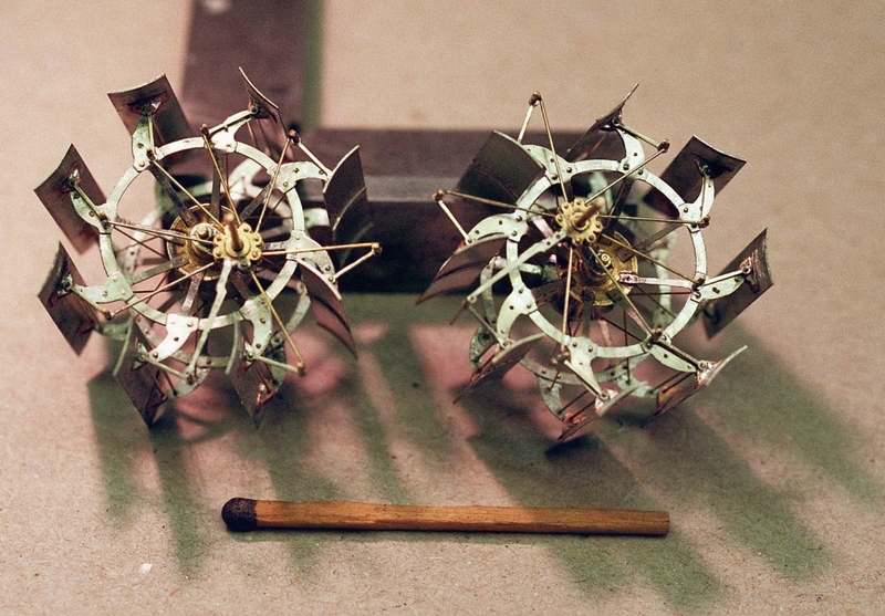
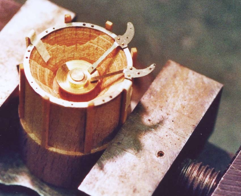
I know a 95 year old gentleman in Germany who has made several display-models with fully feathered side-wheels soldered up from brass parts ... in 1:100 scale
-
You are lucky, that these sternwheelers used fixed blades 😈 Looking good 👍🏻
-
Sorry, to have killed your linoleum-dream 🫢 I gather you have to teleport LULA then into the 1900s or so.
- 732 replies
-
- 4
-
-

-
- Lula
- sternwheeler
- (and 1 more)
-
Deck Cleats
wefalck replied to hof00's topic in Discussion for a Ship's Deck Furniture, Guns, boats and other Fittings
The size of cleats need to be adapted to the size of line to be belayed on them. Even on small boats the cleats for sheets can be anything between 500 mm and 700 mm long. The ones that double also as cleats for mooring lines may span two bulwark stanchions. -
If linoleum, I would have thought of plain so-called Battleship-Linoleum in iron-oxide red ... However, linoleum wasn't invented until the mid-1860s by Walton, who remain the main producer (through subsidiaries) in Europe. Some years ago I did quite extensive research on the possible use of linoleum on the original configuration of SMS WESPE, but concluded that 1876 was too early. Shipboard use didn't really commence before the 1880s. Another option is wax-cloth, forerunner and inspiration for linoleum. I believe waxed cloth was used as cheap floor-covering from around the 1840s, but doubt that it would have stood up to rough shipboard use. It's the same kind of stuff they still sell as tablecloth today. To be honest, I think the most realistic bet would be plain wooden flooring.
- 732 replies
-
- 4
-
-
-
- Lula
- sternwheeler
- (and 1 more)
-
Deck Cleats
wefalck replied to hof00's topic in Discussion for a Ship's Deck Furniture, Guns, boats and other Fittings
I gather, learning to sail helps ... in many cases you the business end partly around a cleat, pin or spill head, because the friction helps you to control the line and takes out jerks. There is also a difference between 'belaying' and 'fastening'. Belaying end always refers to the business end of a line, the one that is handled. The other end is 'made fast', e.g. with a shackle through a spliced eye to an eye-bolt. -
Deck Cleats
wefalck replied to hof00's topic in Discussion for a Ship's Deck Furniture, Guns, boats and other Fittings
Indeed, a tackle or at least a single block. -
That's called a 'jig' and is used in manufacturing and assembly all the time ... one can also use cardboard for jigs that don't have to be terribly precise or carry loads.
-
Hanks for attaching staysails to stays
wefalck replied to Dr PR's topic in Masting, rigging and sails
"Some people call the rope coils created when belaying ropes to belaying pins "hanks" but this is a misuse of the term." I am not a native English speaker (though I consider myself bilingual ...), but for me a hank of yarn/rope was yarn or rope coiled up. The use of the term 'hank' for the kind of hooks used to attach staysails to stays seems to be in line with the etymology of the word: https://en.wiktionary.org/wiki/hank. In German we call these thingies 'Stagreiter' i.e. 'stay-rider' ... -
Deck Cleats
wefalck replied to hof00's topic in Discussion for a Ship's Deck Furniture, Guns, boats and other Fittings
I am confused by the wording now: tackles usually 'hook' to eyebolts, but their runners are then belayed to pins or cleats. Cleats are for belaying, not for making fast tackles. -
Building the Beakhead
wefalck replied to acaron41120's topic in Building, Framing, Planking and plating a ships hull and deck
Never had to build one, but in general, in situ-construction ensures that the part actually fits. Otherwise, you would need to have a sort of jig that exactly reproduces the attachment points. Perhaps a hybrid strategy, building the elements that attach to the ship in situ, taking them off and completing the structure off-ship might help. -
I think on a 'real' ship they would be called 'knightheads', but these are heavy timbers that bolt onto the deadwood.
- 312 replies
-
- 3
-
-
-
- Chile
- Latin America
- (and 6 more)
-
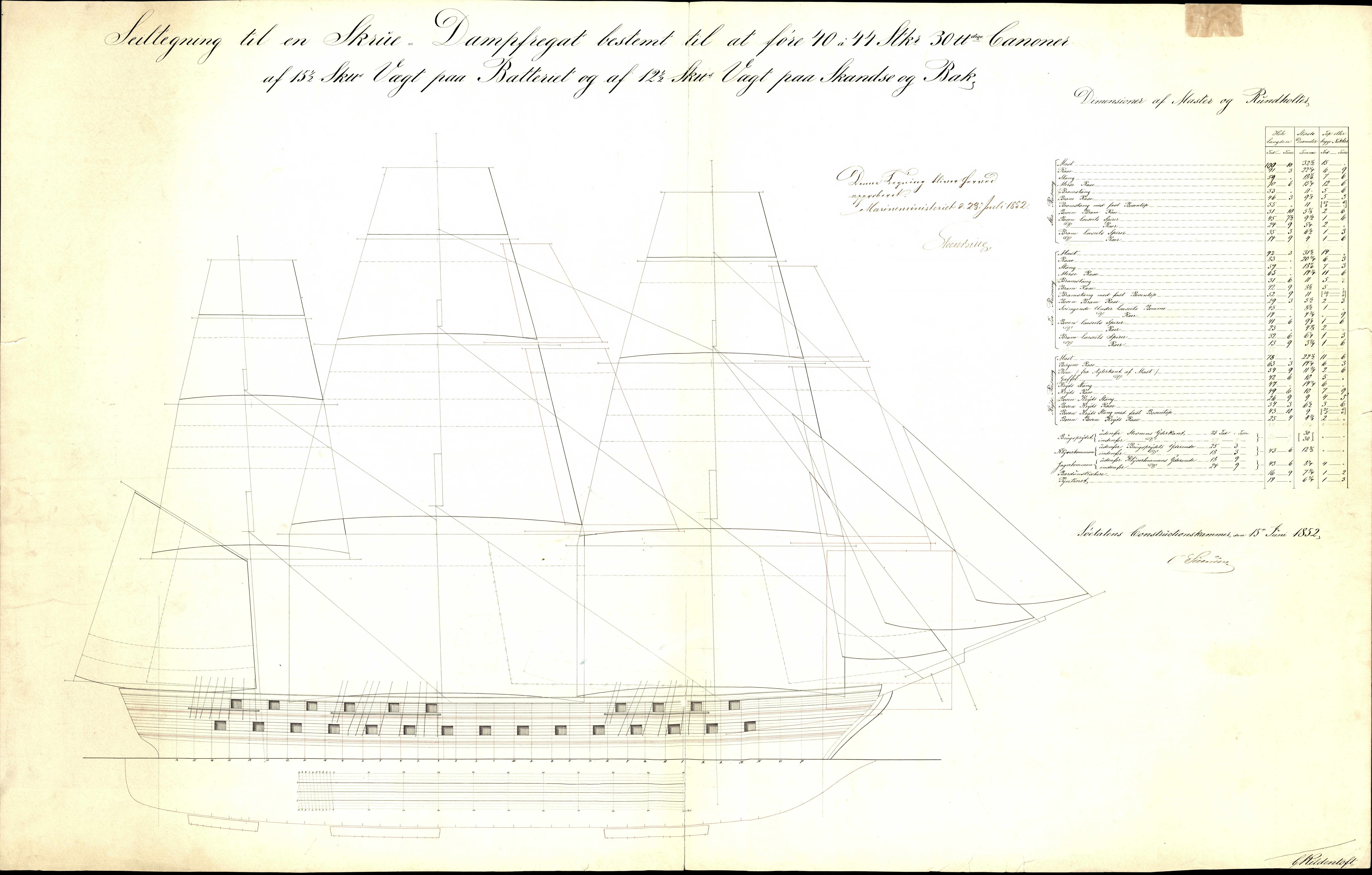
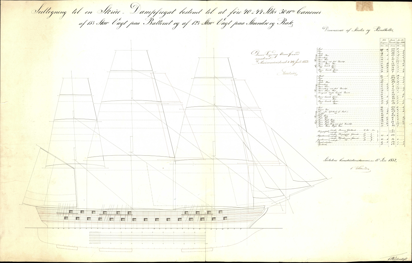
For drawings on Danish naval artillery 1850ff you may want to browse the archive for number G2092 and above: https://arkivalieronline.rigsarkivet.dk/da/billedviser?epid=17149179#190263,31920089 As I said earlier, rigging plans and details can be found under numbers G1872 and above: https://arkivalieronline.rigsarkivet.dk/da/billedviser?epid=17149179#190444,31922330
-
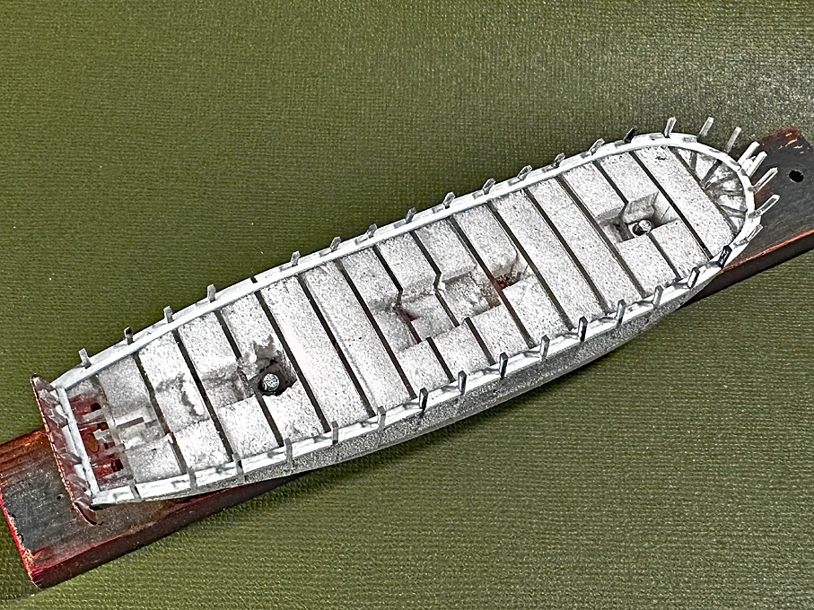
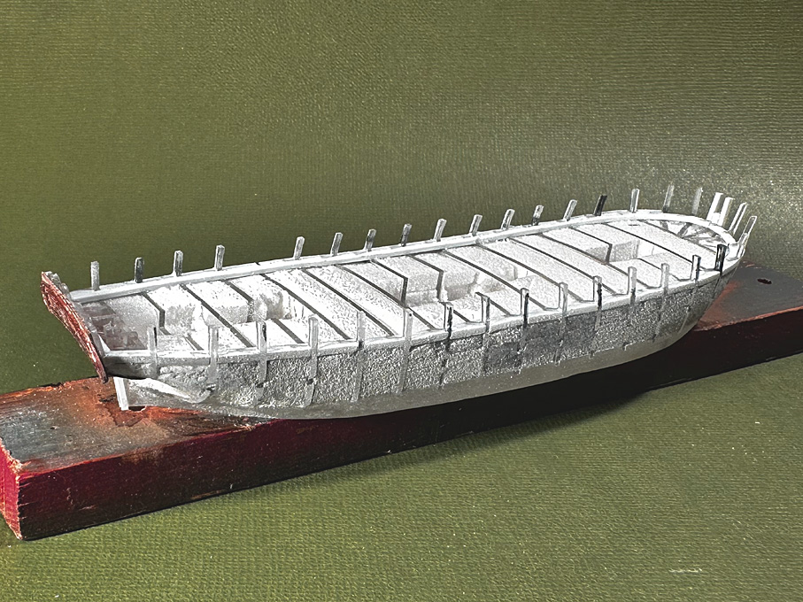
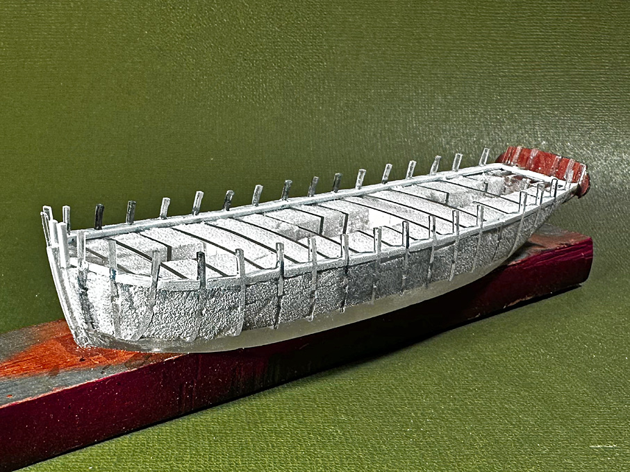
With these 'non-standardised' designs, one can always take a bit of artistic license. The builders themselves probably would have adapted to circumstances. I wonder, why they used this stepped design of the stanchions? Did bolts go through the 'ears' into the covering board? It is common design for rails to either extend the frames above the covering board or to bolt some thinner material to the frames that then extends upwards. However, these low rails probably only served to keep equipment or loads from rolling over board, so they don't need to be terribly sturdy.
- 312 replies
-
- 5
-
-
- Chile
- Latin America
- (and 6 more)
-
Didn't I send you at some stage a list of all the drawings that pertain to JYLLAND from the archives of the Danish Navy Shipyard? Basically, archival Nos. G1859 to G1896 pertain to her, including a rigging plan (G1872 and G1873). There are additional mast details at G4882 to G4900. The mast actually look surprisingly vertical.
-
Slow Progress (as usual) The run of the planking and their layout will be determined by three structural members, namely the rail on the bulwark as upper edge, the covering board, which marks the lower edge of the bulwark and the upper edge of which is marked in the original drawings, and the wales, the upper edge of which are also marked in the original drawings. In order to physically define the top edge of the covering board, the waterways have to be installed first. The consist of a 1 mm x 1 mm styrene strip running along the inside of the bulwark stanchions. This is thicker than the actual water ways would be, but the thickness includes that of the covering board inside the bulwark stanchions. The space between the stanchions was filled with small pieces of 1 mm x 1.5 mm styrene strip. This is a tad wider than needed, but allows me to sand them down to the actual profile outside of the stanchions. While in theory the stanchions are spaced equidistant, the filling pieces still required a bit of sanding to fit them snuggly. There are actually many different designs for the waterway/covering board arrangement and not any particular construction method is being followed here. The idea is to give the right visual impression after painting, not to follow prototype construction method. In fact, it would have been rather difficult to cut out the notches for the stanchions from the styrene strip representing the covering board at these dimensions, as would have been the prototype method. The arrangement will be completed by a 0.5 mm x 0.75 styrene strip that will be shaped to a half-round profile using a scraper fashioned from a piece of razor-blade and that will be cemented along the upper edge of the covering board. To be continued
-
Yep, jigs make life easier and more precise 👍🏻
-
Again 'fonds dur' is an application, that can be achieved with a variety of materials, such as shellac plus pumice (the basis of classical 'French Polish'), nitrocellulose plus pumice, acrylics plus something as filler etc.
-
These hot glues work for almost everything, but 'technically' they are not quite correct solutions. There is also the risk that when the plasticisers diffuse out, the bond becomes brittle and the glued parts fall apart ...
-
The problem is that people confuse 'materials' with 'applications'. A lot of materials can be used for the same application and a lot materials can be used for different applications. Shellac can be used as a cement, as a varnish, as a binder in paints (with pigments added), as sanding sealer (with pumice added), for seals, etc. etc. I fully agree and have repeatedly said so in this forum, that mixing varnish- and paint-systems can lead to trouble unless you really know what you are doing.