wefalck
-
Posts
6,665 -
Joined
-
Last visited
Content Type
Profiles
Forums
Gallery
Events
Everything posted by wefalck
-
 Thanks for the link above. I think I should try to get hold of a copy of the 'Pyle', though you confirmed my suspicion that the drawings wouldn't be too detailed. I have been on various trips from Anegada down to the Grenadines, but not on all islands between the early 1990s and the early 2000s. At that time there were still quite a few wooden sailing-boats and canoe-like boats around. Unfortunately, the FAO caused havoc from the 1950s on to the tradtional boats all over the world, because they were considered inefficient. They promoted standardised GPR-boats based on modern North-American models and equipped with outboard engines. In many regions they seem to have been in use long enough to kill much of the local skills in boatbuilding. However, I have seen people returning to the tradtional craft, because they were cheaper to maintain and one could do so using local materials, skills, and infrastructure. A holed GPR-boat is not so easy to fix, if you don't have access to the resins, matts etc.
- 312 replies
-
- 2
-

-
- Chile
- Latin America
- (and 6 more)
-
The question is also does one really need to 'protect and finish' painted areas? On a display model, this may not be really needed. The only reason I can see why one wants to varnish a previously painted area is that one wants to have a uniform sheen. However, on a real ship surfaces treated differently would have a different sheen. Many modellers simulate surfaces that on a real ship would have been treated with wood-tar by leaving the wood 'bare' and only varnish it. Or they want to emulate the look of historic models, where the wood would have been varnished or oiled. In this case I would first varnish the whole model and then paint the areas that would have been painted. Beware that acrylics are probably not sticking well to oiled surfaces, even when oxidising oils, such as lineseed or tung oil have been used.
-
It's more physics than chemistry here. Shellac and acrylic paint may have different thermal expansion coefficients. So, depending on the thickness of the respective layers, they may shrink or expand differently, leading to crackelure. You also can crackelure, when the outer layer shrinks while drying. This can make the inner layer even lift off the surface. And yes, chemistry can also play a role, particularly when painting with a brush, where layers tend to be thicker than when airbrushing, which means that you bring more solvent to the first layer of paint that can react with this paint. In general, like with like adheres better. However, I agree there may be situations where you want to use shellac on acrylics. Say when you try to simulate varnished wood with paint and want to get the same kind of sheen as with shellac. However, I would in any case try with acrylic varnish and see what it looks like.
-
Interesting read, thank you! There seem to be two editions of the 'Pyle', which one do you have? Pyle, D.C. (1981): Clean, Sweet Wind: Sailing Craft of the Lesser Antilles.- X+292 p., Preston, Md (Easy Reach Press). Pyle, D.C. (1998): Clean, Sweet Wind: Sailing with the Last Boatmakers of the Carribean.- 212 p., Camden, Me (McGraw-Hill Professional Publishing). It has been in my literature list for a while, but I didn't know that it contains lines plans. I had a copy of Doran's article on the Tortola-boat for years, since a sailing trip to the British and US Virgin Islands. I tried to find out more about the local boats, but there is not much written about them. There is also another article by Doran about the Leeward Island boats that I can dig out from my archives: Doran, E., Jr. (1964): Commercial Sail in the Leeward Islands.- American Neptune, 24: 95-108, Plate 13/14.
- 312 replies
-
- 4
-
-

-
- Chile
- Latin America
- (and 6 more)
-
But why, would one do that? It is always better to stay within one paint system.
-
Actually, shellac is dissolved in alcohol and some acrylic paints use an alcohol/water-mixture as solvent. In this case, it would be conceivable that there is some interaction with the acrylic paint, when it is not fully cured. In acrylic paints the metacrylic molecules form a crosslinked network from which it can take days or weeks for residual solvent to diffuse out. That's why acrylic paints stay rubbery for some time, particularly when applied in a thicker layer. If for whatever fancy reason you want to put shellac over acrylic paints, you should better wait for several weeks ...
-
Why would you want to do that?
-
The problem we have in Europe, is that these kinds of shops are slowly dying out. Owners give up, because they can't find successors, when they retire - such shops are a life-style, rather than a 'job' and young people look into life-styles that they consider more glamorous and with shorter working hours. When I was living in Vienna in the early 2000s, there were still many such shops, but they died quickly, when the ceiling on prices for commercial leases were removed by the city council - there wasn't enough margin in these businesses to satisfy the greed of the property owners. Whenever I am in less-developed countries, I am on the look-out for such shops ...
- 312 replies
-
- 7
-
-
- Chile
- Latin America
- (and 6 more)
-
Vomag Omnibus by RGL - FINISHED - Roden - 1/72 - PLASTIC
wefalck replied to RGL's topic in Non-ship/categorised builds
Of course, it was set up after 18.01.1871, the day when the 2nd Empire was offcially proclaimed. Like the railway it retained 'Reich' in its name, even after 1919, when the Empire officially ceased to exist and during the republican years from 1919 to 1933. Nice project, btw. I wasn't aware that busses of the Reichspost had a red livery. It appears that these were town-busses in large cities operated by the Reichspost and the idea was to distinguish them visually from the yellow overland-busses. -
Is this an original early Sheave bearing??
wefalck replied to Tiefel's topic in Masting, rigging and sails
Blocks with roller bearings appear in the later 19th century literature. When they have metal sheaves, they are usually meant for wire ropes. -
Yep, that was my thought also, to cover the baseboard with some select 'mud' and show the boat resting a bit leaned over. That would not preclude set sails, as they could be just hanging down limp, set to dry. I am not coming across very freqently these stir-sticks (in fact I dislike them and try to avoid places where they don't use proper cutlery and crockery 😉), but most I have seen appear to be of surprisingly good quality. Another such 'secondary' source of thin strips of wood are the sticks/spatulae used by doctors, when they look down your throat. I gather (para)pharmacies or drugstores may have them. Most I have seen seem to be beech or birch. I also know about people going around on days, such as New Year Day, collecting the sticks from firework-rockets ...
- 312 replies
-
- 5
-
-
-
- Chile
- Latin America
- (and 6 more)
-
Ab, you are a lucky man to receive such gifts! Didn't Van de Velde the Older specialise in larges-size grisailles originally? I am quoting from memory and didn't check against my books on them. And, compared to your speed of building I don't even look like snail, but more like a barnackle ...
- 77 replies
-
- 1
-
-
- Royal Yacht
- card
- (and 1 more)
-
@druxey I was talking about seven to ten strakes not 7" to 10" plank width. 10" seems to be rather wide for a boat ...
-
best SECOND model ship kit recommendations
wefalck replied to palmerit's topic in Wood ship model kits
The best thing would be to develop before an interest in a certain subject area (or a particular ship) and then pick a kit, if it has to be that. That background interest keeps one going even through difficult times and also leads to improvements on the kit. -
Seven to ten strakes seem to be numbers commonly seen. The number of strakes needed depends also on the radius of the bilge. A sharp bilge may require narrower planks than a wide rounded one. One tries to get away with as few strakes as the available material and the curvature permits. Wide strakes may require complex bending that is difficult.
-
Young branches at least are quite flexible and tough. In some parts of Europe willows were kind of trained or trimmed in a particular way to give lots of shoots, which were used also for basket weaving and the like. These willows once were a characteristic sight along rivers and creeks. They looked like mushrooms with a lot of sticks coming out of them. As not so many baskets or house walls are woven anymore, the practice has largely died out. I could imagine that such branches with the bark stripped off (which is easy) would make good tree-nails. These tree-nails are also flexible, adding to the flexibility of the hull.
-
The engine looks really good. Do you have some close-up pictures? How did you construct it? In a way I am surprised that they used what looks like Corliss-engines with valves, rather than simple sliding valve engines as in locomotives. Talking about bucket-dredgers: the most difficult parts would be the buckets. Their rounded features would need to be reproduced by e.g. vacuum-forming or hammering around a wooden former or perhaps 3D-printing ...
- 732 replies
-
- 3
-
-
-
- Lula
- sternwheeler
- (and 1 more)
-
Well, one can use 3D-printing to make masters for lost-wax casting in brass ...
-
Not surprising that the customer is happy. Job well done 👍🏻
-
I got a notification of a post from Kevin, but it seems to have disappeared. It was about something dangling from the counter. I haven't seen the picture in question, but I assume that these were the 'man-over-board-buoys', plates with knotted ropes attached to them.
- 62 replies
-
- 1
-
-
- belle poule
- OcCre
- (and 1 more)
-
Cones go down to near zero (at least, if one has quality ones). I am holding both, the part and the bit in pin-vises respectively.
-
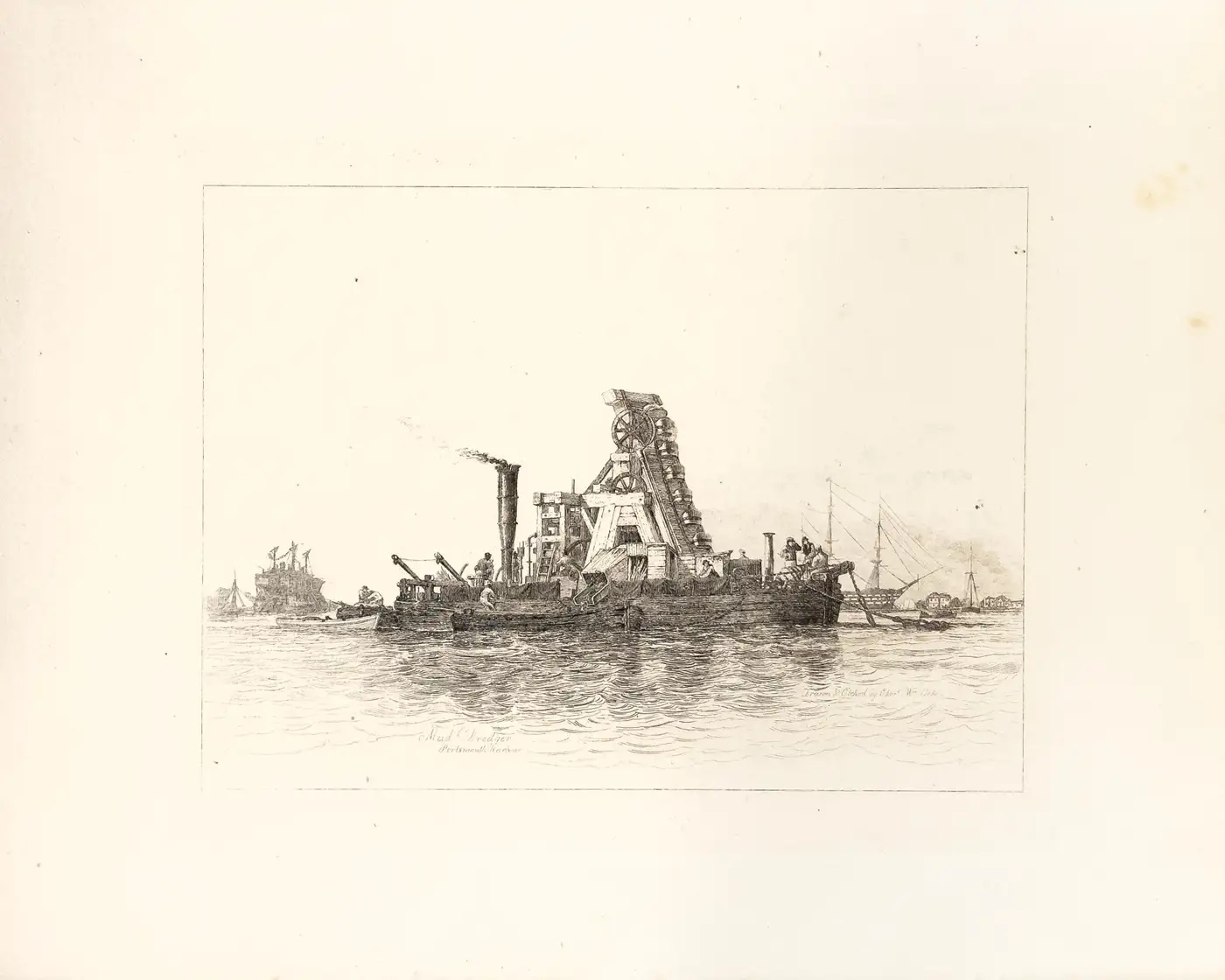
A bucket dredger also has been on my 'list' for decades - lots of opportunities for turning, milling, cutting gear-wheels and such. I have also collected quite a bit of drawings on them from the mid to late 19th century. It is interesting to see in first photograph, that they simply attached the bucket arm to the side of a sternwheeler. Given that many rivers in Europe are a lot smaller, they were often not self-propelled in the early years, but put out anchors upstream and then moved along while working, using these mooring points. Otherwise, they needed a tug to move them to different locations. They usually where catamaran-like with the dredging arm between the two separate hulls. Early ones had often wooden structures for the dredging arm. There is a 1829 drawing/etching by E.W. Cooke of one like that:

- 732 replies
-
- 11
-
-
- Lula
- sternwheeler
- (and 1 more)
-
Well, in Europe as far as I am aware, locomotive smokeboxes were always black. I don't recall having seen anything else. The same for traction engines and the likes. On smokeboxes (and ships' funnels incidentally) you have to use a paint with a heat-resistant pigment, basically soot/carbon-black or graphite. That's why steam-ship funnels are black. If you wanted to have a company logo on it you had to use a sleeve with an airspace in between or a double-walled stack. I remember from my childhood days that there was something called 'stove-paint' with which one painted the smoke pipes between the stove and the wall. It was either black or silvery, so the pigment was either carbon-black, graphite or some metal powder (probably aluminium).
-
You are right @druxey, that last one does not have a number, neither in the longitudinal section nor in the body-plan. I wasn't aware that this could be an indication of a cant-frame. What also tricked me, was that in the longitudinal section there is a station without number equidistant from the other stations that appears in the body-plan as well.
-
Yep, I wasn't interested in the rig in museum configuration. I was more interested in the deck arrangements etc.