


wefalck
-
Posts
6,652 -
Joined
-
Last visited
Content Type
Profiles
Forums
Gallery
Events
Everything posted by wefalck
-
 Once you were washed over board, you didn't care about anything anymore, that was the end of it ... Talking about negotiating stairs, which were always inclined by definition, on a ship you do this always backwards when going down, so you can hold onto the sides and your centre of gravity is over the stairs. So, no need for hand-rails.
 -
Very professional looking indeed 👍🏻
-
Nice Scandinavian-looking outhouse you built there 👍🏻 ... and the boat is coming on nicely. One can imagine almost an old Nordic/Viking ancestry at this stage of building.
-
If there wasn't the messing around with the monomer resin. Hopefully, in couple of years or so I may have a dedicated workshop-room, but in the corner of the study in our apartment that is not such a good proposition 😞 The is also a steep learning curve to get to master the CAD modelling programmes, so I had some basic training in Auto-CAD a few years ago and regularly use my 2D CAD program. On another forum I am following a couple of guys, who model and print whole ships in 1/100 scale. Wonderful stuff they do. I am envious. On the other hand I would loathe to replace my 'historical' lathes and milling machines because they have become obsolete by this new technology. It took me years to build it up and now that it is in full working order it has become kind of obsolete in a way 😲 Well, at least for building 'realistic' shipmodels, perhaps not for 'artisanal' style models.
-
I am not really familiar with skipjacks, but if they had plain wooden decks, why would you want to stain and varnish it? Some people leave bare wooden decks bare wood, but one could also apply a sanding filler/shellac to aid sanding or rubbing down with steel-wool.
-
Ad 1: Brails on gaff-sails could only be used, when the sail was loose-footed, i.e. only attached to the boom by the sheet; you can't even use the brails with sail laced to the boom. Ad 2: My understanding of brails is that they were used on square sails to take up some of the weight of the sail when reefing or furling it; on gaff-sails they could be used to help furl the sail against the mast, particularly when rigged with a standing gaff; they were also used when sailing to adjust the centre of effort of the sail plan, to balance the ship on a particular course or to help tacking/going about. Ad 3: I don't really know, but as both storm-sails are smaller than the regular spanker, the hauling point would have to be further forward along the boom; their sheet could also be belayed at any convenient point, e.g. the rails; I wonder actually, why there shouldn't be any sheet for the spanker - somehow it has to be attached to the boom?
-
Professional etchers use either a foam- or a spray-etching process to achieve uniformity across the fret and reduce underetching of the edges. One thing I will try one day is to laser-print the design onto so-called thermotransfer-paper and iron the design onto the prepared metal sheet. One has to make a sleeve from the thermotransfer-paper with mirror-images of the design matching up exactly, so that the etching takes place from both sides. This reduces underetching and allows surface etching (say rivets), if the two designs are made appropriately. The toner acts as the resists and one does not need a separate etching mask and photoresist covered metal sheets.
-
Plexiglas (acrylic glass) is much harder and stiffer than polystyrene. It machines very well in comparison and keeps a keen edge. It can also be polished, unlike styrene, which comes handy when building skylights etc. I am kind of partial to Plexiglas, as I sort of grew up with it. My father worked for the pharmaceutical subsidiary to the parent company Röhm GmbH, the original manufacturer of Plexiglas. So we had easy and cheap access to it. In fact most of my supplies were acquired before my father retired in 1986, so the material above is probably more than 40 years old. A problem is that Plexiglas is not available in thicknesses of less than 0.8 mm. So, the 'structural' parts of the model will be made from Plexiglas, while the planking will be styrene - not ideal, because I would have preferred something stiffer. I could use bakelite-paper, which works very well for the purpose, but I want to engrave some of the planks (as one will see later on in the building-log) and that does not work very well with the brittle bakelite. Also, I would have to glue everything with CA, which I don't like too much.
-
I wonder, whether there aren't any photo-etching service suppliers on your side of the pond that cater (also) for modellers? Over here in Europe we have several established in the market for years - I know one or two in Germany, the Czech Republic and Poland (the latter two are price-wise quite competitve due to lower salaries). I had a go at photo-etching myself a few years ago, but with mixed results. The main issues I identified was producing masks of sufficient black density with my printers and the primitive etching process in cuvettes I used. Even for the small frets I made uneven etching across the fret was a problem. Our parts are quite different from PCBs, because we have parts that are to be etched through (no backing board) and we also etch in different layers (surface etching). Most home-made PCBs are also unlikely to have such fine and dense details as are required for modelling.
-
It begins to look ship-shape 👍🏻 You are in the same dilemma as we all are who try to depict working boats in their real condition: how do I reproduce the irregularities and haphazardness of the 'real thing' without the model looking poorly executed. A problem that our colleagues who build historic ships in an 'artisanal' style to show their woodworking etc. skills don't have. I think there is no problem in using different plank widths or varying shift patterns as long as the planking us such is done neatly. Even if boatbuilders have to do with the random material that is available, they usually take care e.g. to plane/adze the surfaces neatly with no plank edges sticking out etc. I observed this even at the rough beach-building places for dhows in Zanzibar. The irregularities have to be to 'scale'.
- 312 replies
-
- 3
-

-
- Chile
- Latin America
- (and 6 more)
-
The swarf from acrylic glass is quite crumbly and brittle, so it is easy to remove with a bristle brush.
-
There won't be any wood on this model. On the prototype only part of the wale, the deck, mast and spars would not have been covered in paint. At this scale, even the grain of box-wood would difficult to handle and Plexiglas keeps much crisper edges. More details on the planking etc. at its time 😉
-
Normal household silver or brass polish will do. It comes usually either as cream in pots or semi-liquid in bottles or tubes. Rinse well afterwards.
-
This appears to be a pivoting support rod for the yard that is attached to the parral. These seem to have come into use in the 1880s or so for lower and lower top-sail yards that not normally were raised or lowered and replaced halliards. Check out UNDERHILL, H.A. (1946): Masting & Rigging the Clipper Ship & Ocean Carrier.- 304 p., Glasgow (Brown, Son & Ferguson). I think there is a drawing in there. The rod was hinged to a central band on yard connected with the parral and its bottom end was hinged to a band lower down on the mast. The hinges allowed to brace the yard.
-
If I understand correctly, LYNX was a kind of privately built privateer? So, it may not have followed any navy pattern/regulation. As these are upper deck guns, any eye-bolts would be sitting in the bulwark stanchions. Bulwark stanchions do not have any support from above, so they would be heavily strained on bending, resulting from the recoil. In consequence, one would probably try to distribute the strain from the breech-rope and the tackles over different stanchions and to keep the eye-bolts as low as possible. The question then would be, how the stanchions might have been spaced in order to find a point of attachment. Are there any naval regulations/USN handbooks for the period in question? I am not familiar with the period/country. Otherwise, RN practice would probably the next thing to look for. I would shy away from looking at modern interpretations and models, as one does not what sources the respective author/builder might have used.
-
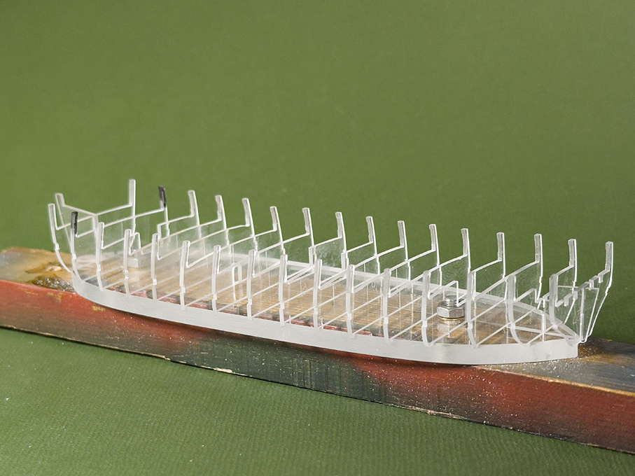
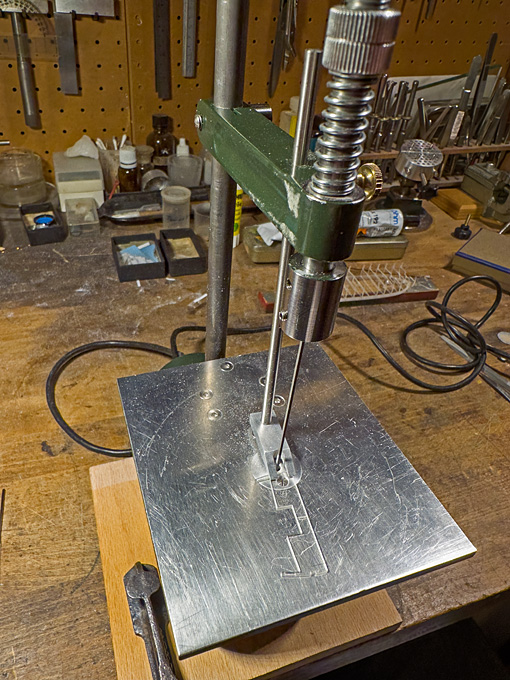
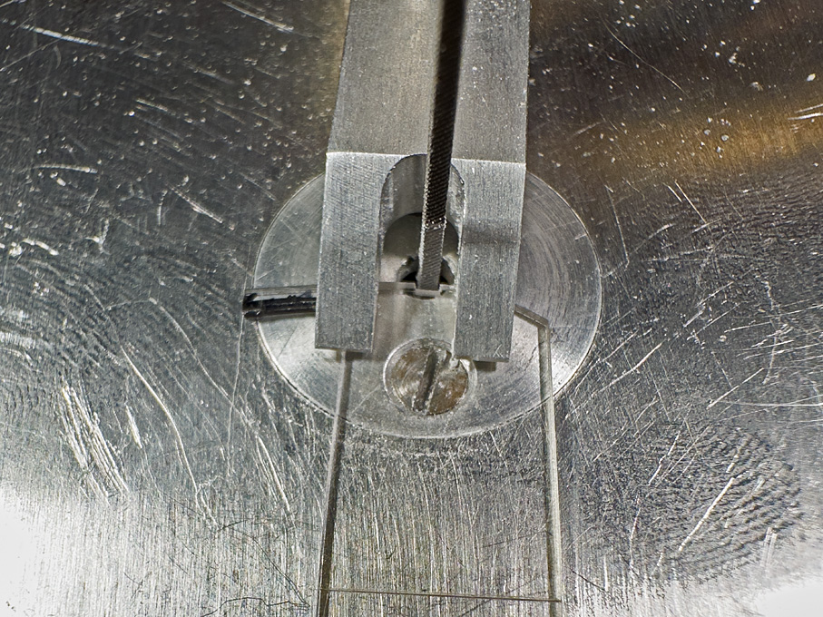
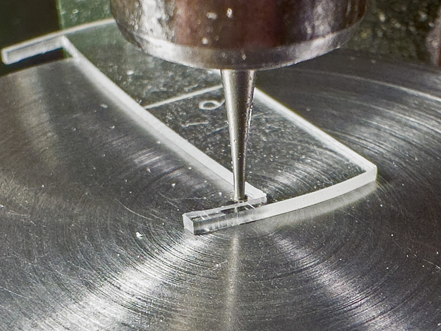
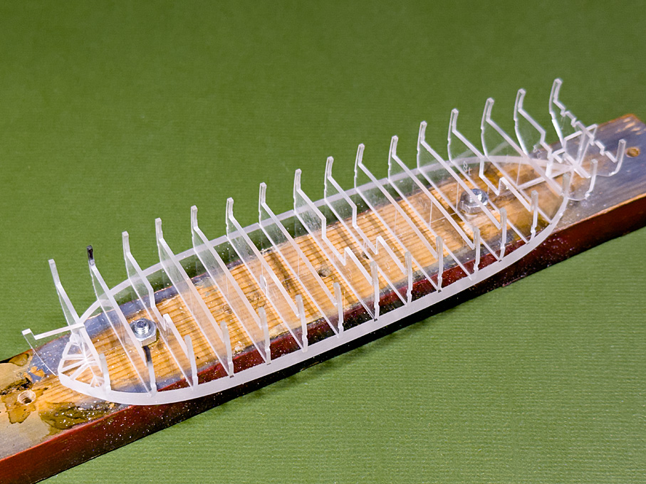
I hope everyone here had a good start into the New Year 2025! *************************************************************** Continuing with the bulkheads Progress over December was slow, due to a couple of travels and a visitor over Christmas, but quite steady. All parts of the backbone have now been cut out and sanded/filed to shape. Dimensional accuracy was checked by placing the parts over a drawing on a LED-backlit board. The cant-frames, however, can only be finished, when the bulkheads have been glued in place. Collection of finished bulkheads I was happy to see that the Plexiglas-sheet is dimensionally very accurate and fitting tightly into the milled slots in the base. This means no particular arrangements need to be made to ensure that they sit perfectly perpendicular on the base. Milling a chamfer on the inside of the stanchions on micro-milling machine set-up as router The bulkheads still required a bit of work. I thought it would be a nice detail to give the future bulwark stanchions a light chamfer over part of their length. This kind of edge-treatment was very common on many ship parts for both, aesthetic reason and to reduce the risk of splintering in case of an impact. It is not seen very often on models though. To this end I had made the router table last autumn. A 0.5 mm drill in a collet served as guiding pin and a small conical burr was used as router. The length of the chamfer was marked on the stanchions before milling it freehand. The result is difficult to photograph on the clear Plexiglas, but will become visible, once the model is being painted. Filing notches for the wales on the shop-made filing-machine Another operation was to cut shallow notches for the wale. The top-edge of the wale is marked in the original drawings and its width was taking from a table of scantlings of a similar ship. Having the wale fixed in that way will give a guidance for the later planking. The shop-made filing-machine in action on the bulkheads The notches were cut with a 1 mm x 1 mm fine machine file on the shop-made filing machine (https://www.maritima-et-mechanika.org/tools/diefiler/diefiler.html). I was lucky to have been able to find on ebay some years ago whole boxes of unused machine files in various shapes, dimensions and cuts. A life-time supply of a tool that is not made anymore. Collection of finished bulkheads To be continued
-
The pump reminds of another project that I have in the back of my mind for some day: a diving-barge with an old-time diver with the large copper helmet, foldy rubber suit, chunky leaded-down boots, etc. They would be supplied with air through a hose. I remember one seeing as a boy, inspecting the pile-driver's work in Kiel harbour. Must have been around 1961 or 1962.
- 732 replies
-
- 5
-
-
- Lula
- sternwheeler
- (and 1 more)
-
Feel free to ask questions. There are members here with 30+ years of experience in machining ... It is also good to keep in mind, that lathes and mills are 'self-replicating' machines in the sense, that you can make parts on them that improve their performane or widen the spectrum of applications by making attachments. In this sense it is also useful to look at old-time (pre-WWI) machinists handbooks from a time when machine-tools were less sophisticated and one had to make a lot of parts/attachments oneself.
- 53 replies
-
- 4
-
-
- Drill Press
- Milling
- (and 1 more)
-
As has been noted in other threads here, it helps to draw up a list of things you really want/need to do with the machine and a list of things of which it would be nice, if it could do this as well. The next step is to think about the enveloppe of the parts you expect to work on, i.e. max length, max width/length or diameter. One also needs to think about the materials you expect to work on. Finally, what is the smallest and biggest hole you expect to drill. This determines the chuck or collet capacity and the precision and sensitivity required. Most hobby machines are ok down to 0.5 mm or even 0.3, but below that concentricity and sensitivity of movement may not be good enough, resulting in drill breakage. Milling machines in general are meant to mill, not to drill. Hence, many do not have quill, but you need to lower/lift the head with a handwheel that works on a leadscrew. That is a very precise and safe way for drilling holes, but also very tedious, when you want to drill many holes of medium precision. For some mills drilling quills are available as extras or so-called sensitive drilling-attachments, which is essentially a sleeve fitting into the main chuck/collet with which a light drill-chuck can be moved up an down. As mentioned in my previous post, I would look into using collets for model work, rather than a drill-chuck. Many drill-presses, however, do not allow to replace the chucks with collets. In some cases, aftermarket ER collet-chucks may be available. I am not terribly familiar with the current market for drill-presses or milling machines, as I am fully kitted out, so the above comments are meant to provide you with indications for what to look for in the machines.
- 53 replies
-
- 3
-
-
- Drill Press
- Milling
- (and 1 more)
-
Can't comment on the current quality of the PROXXON drill-press, but had the previous model since the early 1980s and it is still going strong, though it has seen considerable abuse by working too hard. In any case, I would recommend to go for collets, rather than using the Jacobs-chuck - less bulky and more precise. I think, PROXXON includes them into the standard kit. At the time I also bought the long column, which came handy for non-modelling projects (hence the abuse), and the kit convert it into a simple wood-lathe (I don't think they offer this anymore since they had the small wood-lathe).
- 53 replies
-
- 3
-
-
- Drill Press
- Milling
- (and 1 more)
-
Well, I assumed that just the same knot as fishermen used for their nets were used. While square/lozenges seems to fairly straightforward to make (fishermen do this free-hand while chatting away on quays, much like women do their knitting), the often seen hexagonal patterns seem to require some sort of framing.
-
31 Aug 1798 - "Beat to Quarters and Stow'd our hammocks in the Nettings and in the Tops and fill'd our Lockers with Shot..." Perhaps you guys have been put on a wrong track by the short-hand writing and the lack of commas? I would have just read it like this: 31 Aug 1798 - "Beat to Quarters and Stow'd our hammocks in the Nettings, and [been] in the Tops, and fill'd our Lockers with Shot..." Much less puzzling, though hammocks were indeed used as protection against small-arms fire, so why not in the tops as well ...
-
This appears to be cart-mounted fire-pump - the engravings in the back corroborate this. They came into use in the 18th century and were finally surplanted by IC-engine-driven pumps in the 20th century (there were also two-wheeled steam-driven cart-pumps, but they were expensive). Every village used to have at least one, if they couldn't afford a bigger one or when the streets didn't allow access by four-wheeled ones. They were also common in industrial establishments and shipyards for rapid intervention.
- 732 replies
-
- 6
-
-

-
- Lula
- sternwheeler
- (and 1 more)
-
Edge bending brass strip?
wefalck replied to alde's topic in Metal Work, Soldering and Metal Fittings
To me it appears than that very little bending is actually required. -
Edge bending brass strip?
wefalck replied to alde's topic in Metal Work, Soldering and Metal Fittings
Are you sure that this should be a part bent into a U and not two parts that meet over the bowsprit in a seam that runs parallel to the bowsprit? I don't think I have ever seen the U-shaped solution on a real ship.